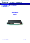
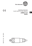
1
Operating instructions
Retro-reflective sensor
UK
O6P300 / 01 01 / 2015
O6P3
1 Preliminary note
1.1 Symbols used
►
>
[…]
→
Instruction
Reaction, result
Designation of pushbuttons, buttons or indications
Cross-reference
Important note
Non-compliance can result in malfunctions or interference.
2 Functions and features
In conjunction with a prismatic reflector or reflective tape the retro-reflective sensor detects objects and materials without contact and indicates their presence by
a switching signal.
3 Installation
►► Fit the prismatic reflector or the reflective tape behind the object to be detected.
►► Align the retro-reflective sensor to it and secure it to a bracket.
Maximum range only with accurate alignment.
2
4 Operating and display elements
1:
2:
3:
4:
LED yellow - switching output active
Setting potentiometer „sensitivity“
LED green - operation
Selector „output function“
5 Electrical connection
The unit must be connected by a qualified electrician.
►► The national and international regulations for the installation of electrical equipment must be adhered to.
►► Ensure voltage supply to EN 50178.
►► Disconnect power.
►► Connect the unit as follows:
UK
5.1 PNP
Connector M12 pigtail
Cable *
Connector M8 3-pin
Connector M8 4-pin
2
1
4
3
* Core colours: BN = brown, BU = blue, BK = black
3
5.2 NPN
Connector M12 pigtail
Cable *
1
BN
L+
4
L+
BK
3
BU
L
Connector M8 3-pin
L
Connector M8 4-pin
1
L+
2
1
4
3
L
1
4
3
L+
4
3
L
* Core colours: BN = brown, BU = blue, BK = black
6 Settings
6.1 Set the output function
D
L
►► Setting D: dark-on mode
►► Setting L: light-on mode
6.2 Set the sensitivity
►► Increase sensitivity:
turn the setting screw of the potentiometer clockwise.
►► Decrease sensitivity:
turn the setting screw of the potentiometer anti-clockwise.
4
7 Operation
►► Check whether the unit operates correctly.
>> The green LED is lit when the sensor is ready for operation.
>> Dark-on mode: the output is switched / the yellow LED is lit when an object is
detected.
>> Light-on mode: the output is switched / the yellow LED is lit when no object is
detected.
8 Maintenance, repair, disposal
UK
►► Keep the lens of the sensor free from soiling.
►► For cleaning do not use any solvents or cleaning agents which could damage
the plastic parts.
►► After use dispose of the unit in an environmentally friendly way in accordance
with the applicable national regulations.
Faulty sensors must only be repaired by the manufacturer.
Technical data and further information at unter www.ifm.com
5