1
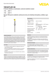
Quick setup guide
TDR sensor for continuous level and
interface measurement of liquids
VEGAFLEX 81
Foundation Fieldbus
Coax probe
Document ID: 47582
Contents
Contents
1 For your safety
1.1 Authorised personnel........................................................................................................ 3
1.2 Appropriate use................................................................................................................. 3
1.3 Warning about incorrect use.............................................................................................. 3
1.4 General safety instructions................................................................................................ 3
1.5 CE conformity.................................................................................................................... 3
1.6 NAMUR recommendations............................................................................................... 4
1.7 Environmental instructions................................................................................................ 4
2 Product description
2.1 Configuration..................................................................................................................... 5
3Mounting
3.1 General instructions for use of the instrument................................................................... 7
3.2 Mounting instructions........................................................................................................ 7
4 Connecting to power supply
4.1Connecting........................................................................................................................ 8
4.2 Wiring plan, single chamber housing................................................................................ 9
4.3 Wiring plan, double chamber housing............................................................................. 10
5 Set up with the display and adjustment module
5.1 Insert display and adjustment module............................................................................. 11
5.2 Adjustment system.......................................................................................................... 12
5.3 Parameter adjustment - Quick setup............................................................................... 13
6Supplement
6.1 Technical data................................................................................................................. 17
Information:
This quick setup guide enables a quick setup of your instrument.
Operating instructions VEGAFLEX 81 - Foundation Fieldbus Coax probe: Document-ID 44215
Editing status of the quick setup guide: 2014-03-17
2
VEGAFLEX 81 • Foundation Fieldbus
47582-EN-140324
You can find further information in the corresponding, comprehensive
operating instructions. This manual is available on the supplied DVD
or in the download area under "www.vega.com".
1 For your safety
1 For your safety
1.1 Authorised personnel
All operations described in this operating instructions manual must
be carried out only by trained specialist personnel authorised by the
plant operator.
During work on and with the device the required personal protective
equipment must always be worn.
1.2 Appropriate use
VEGAFLEX 81 is a sensor for continuous level measurement.
You can find detailed information about the area of application in
chapter "Product description".
Operational reliability is ensured only if the instrument is properly
used according to the specifications in the operating instructions
manual as well as possible supplementary instructions.
1.3 Warning about incorrect use
Inappropriate or incorrect use of the instrument can give rise to
application-specific hazards, e.g. vessel overfill or damage to system
components through incorrect mounting or adjustment.
1.4 General safety instructions
This is a state-of-the-art instrument complying with all prevailing
regulations and guidelines. The instrument must only be operated in a
technically flawless and reliable condition. The operator is responsible
for the trouble-free operation of the instrument.
During the entire duration of use, the user is obliged to determine the
compliance of the necessary occupational safety measures with the
current valid rules and regulations and also take note of new regulations.
The safety instructions in this operating instructions manual, the national installation standards as well as the valid safety regulations and
accident prevention rules must be observed by the user.
For safety and warranty reasons, any invasive work on the device
beyond that described in the operating instructions manual may be
carried out only by personnel authorised by the manufacturer. Arbitrary conversions or modifications are explicitly forbidden.
47582-EN-140324
The safety approval markings and safety tips on the device must also
be observed.
1.5 CE conformity
The device fulfills the legal requirements of the applicable EC guidelines. By affixing the CE marking, we confirm successful testing of the
product.
You can find the CE Certificate of Conformity in the download section
of our homepage.
VEGAFLEX 81 • Foundation Fieldbus
3
1 For your safety
Electromagnetic compatibility
Instruments in four-wire or Ex-d-ia version are designed for use in an
industrial environment. Nevertheless, electromagnetic interference
from electrical conductors and radiated emissions must be taken into
account, as is usual with class A instruments according to EN 613261. If the instrument is used in a different environment, the electromagnetic compatibility to other instruments must be ensured by suitable
measures.
1.6 NAMUR recommendations
NAMUR is the automation technology user association in the process
industry in Germany. The published NAMUR recommendations are
accepted as the standard in field instrumentation.
The device fulfills the requirements of the following NAMUR recommendations:
•
•
•
•
NE 21 – Electromagnetic compatibility of equipment
NE 43 – Signal level for malfunction information from measuring
transducers
NE 53 – Compatibility of field devices and display/adjustment
components
NE 107 – Self-monitoring and diagnosis of field devices
For further information see www.namur.de.
1.7 Environmental instructions
Protection of the environment is one of our most important duties.
That is why we have introduced an environment management system
with the goal of continuously improving company environmental protection. The environment management system is certified according
to DIN EN ISO 14001.
Please help us fulfill this obligation by observing the environmental
instructions in this manual:
•
•
Chapter "Packaging, transport and storage"
Chapter "Disposal"
47582-EN-140324
4
VEGAFLEX 81 • Foundation Fieldbus
2 Product description
2 Product description
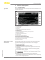
Type label
2.1 Configuration
The type label contains the most important data for identification and
use of the instrument:
1
2
3
4
5
6
7
8
9
10
16
15
14
13
12
11
Fig. 1: Layout of the type label (example)
1 Instrument type
2 Product code
3Approvals
4 Power supply and signal output, electronics
5 Protection rating
6 Probe length
7 Process and ambient temperature, process pressure
8 Material, wetted parts
9 Hardware and software version
10 Order number
11 Serial number of the instrument
12 Symbol of the device protection class
13 ID numbers, instrument documentation
14 Reminder to observe the instrument documentation
15 Notified authority for CE marking
16 Approval directives
47582-EN-140324
Serial number - Instrument search
The type label contains the serial number of the instrument. With it
you can find the following instrument data on our homepage:
•
•
•
•
•
•
Product code (HTML)
Delivery date (HTML)
Order-specific instrument features (HTML)
Operating instructions and quick setup guide at the time of shipment (PDF)
Order-specific sensor data for an electronics exchange (XML)
Test certificate (PDF) - optional
Go to www.vega.com, "VEGA Tools" and "Instrument search". Enter
the serial number.
Alternatively, you can access the data via your smartphone:
•
Download the smartphone app "VEGA Tools" from the "Apple App
Store" or the "Google Play Store"
VEGAFLEX 81 • Foundation Fieldbus
5
2 Product description
•
•
Scan the Data Matrix code on the type label of the instrument or
Enter the serial number manually in the app
47582-EN-140324
6
VEGAFLEX 81 • Foundation Fieldbus
3 Mounting
3Mounting
Protection against moisture
3.1 General instructions for use of the instrument
Protect your instrument against moisture penetration through the following measures:
•
•
•
•
Use the recommended cable (see chapter "Connecting to power
supply")
Tighten the cable gland
Turn the housing in such a way that the cable gland points downward
Loop the connection cable downward in front of the cable gland
This applies particularly to:
•
•
•
Installation position
Outdoor mounting
Installations in areas where high humidity is expected (e.g. through
cleaning processes)
Installations on cooled or heated vessels
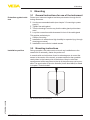
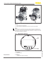
3.2 Mounting instructions
During operation, the probe must not touch any installations or the
vessel wall. If necessary, fasten the probe end.
In vessels with conical bottom it can be advantageous to mount the
sensor in the center of the vessel, as measurement is then possible
nearly down to the lowest point of the bottom. Keep in mind that
measurement all the way down to the tip of the probe may not be possible. The exact value of the min. distance (lower dead band) is stated
in chapter "Technical data".
47582-EN-140324
Fig. 2: Vessel with conical bottom
VEGAFLEX 81 • Foundation Fieldbus
7
4 Connecting to power supply
4 Connecting to power supply
Connection technology
4.1Connecting
The voltage supply and signal output are connected via the springloaded terminals in the housing.
Connection to the display and adjustment module or to the interface
adapter is carried out via contact pins in the housing.
Information:
The terminal block is pluggable and can be removed from the
electronics. To do this, lift the terminal block with a small screwdriver
and pull it out. When reinserting the terminal block, you should hear it
snap in.
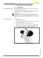
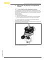
Connection procedure
Proceed as follows:
1. Unscrew the housing cover
2. If a display and adjustment module is installed, remove it by turning it slightly to the left.
3. Loosen compression nut of the cable entry gland
4. Remove approx. 10 cm (4 in) of the cable mantle, strip approx.
1 cm (0.4 in) of insulation from the ends of the individual wires
5. Insert the cable into the sensor through the cable entry
Fig. 3: Connection steps 5 and 6 - Single chamber housing
47582-EN-140324
8
VEGAFLEX 81 • Foundation Fieldbus
4 Connecting to power supply
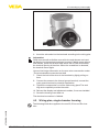
Fig. 4: Connection steps 5 and 6 - Double chamber housing
6. Insert the wire ends into the terminals according to the wiring plan
Information:
Solid cores as well as flexible cores with wire end sleeves are inserted directly into the terminal openings. In case of flexible cores without
end sleeves, press the terminal from above with a small screwdriver,
the terminal opening is then free. When the screwdriver is released,
the terminal closes again.
You can find further information on the max. wire cross-section under
"Technical data/Electromechanical data"
7. Check the hold of the wires in the terminals by lightly pulling on
them
8. Connect the screen to the internal ground terminal, connect the
outer ground terminal to potential equalisation
9. Tighten the compression nut of the cable entry gland. The seal
ring must completely encircle the cable
10. Reinsert the display and adjustment module, if one was installed
11. Screw the housing cover back on
The electrical connection is finished.
4.2 Wiring plan, single chamber housing
47582-EN-140324
The following illustration applies to the non-Ex, Ex-ia and Ex-d version.
VEGAFLEX 81 • Foundation Fieldbus
9
4 Connecting to power supply
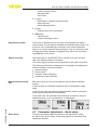
Electronics and terminal
compartment
2
3
0
(+)1
4
1
1
0
Bus
2(-)
5
6
7
8
5
1
Fig. 5: Electronics and terminal compartment, single chamber housing
1
2
3
4
5
Voltage supply, signal output
Contact pins for the display and adjustment module or interface adapter
Simulation switch ("1" = mode for simulation release)
For external display and adjustment unit
Ground terminal for connection of the cable screen
4.3 Wiring plan, double chamber housing
Terminal compartment
The following illustrations apply to the non-Ex as well as to the Ex-ia
version.
2
3
Bus
(+)1
2(-)
5
6
7
8
4
1
Fig. 6: Terminal compartment, double chamber housing
1
2
3
4
Voltage supply, signal output
For display and adjustment module or interface adapter
For external display and adjustment unit
Ground terminal for connection of the cable screen
Information:
The use of an external display and adjustment unit and a display and
adjustment module in parallel in the connection compartment is not
supported.
47582-EN-140324
10
VEGAFLEX 81 • Foundation Fieldbus
5 Set up with the display and adjustment module
5 Set up with the display and adjustment
module
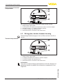
5.1 Insert display and adjustment module
The display and adjustment module can be inserted into the sensor
and removed again at any time. You can choose any one of four different positions - each displaced by 90°. It is not necessary to interrupt
the power supply.
Proceed as follows:
1. Unscrew the housing cover
2. Place the display and adjustment module in the requested position onto the electronics and turn to the right until it snaps in
3. Screw housing cover with inspection window tightly back on
Removal is carried out in reverse order.
The display and adjustment module is powered by the sensor, an additional connection is not necessary.
47582-EN-140324
Fig. 7: Installing the display and adjustment module in the electronics compartment of the single chamber housing
VEGAFLEX 81 • Foundation Fieldbus
11
5 Set up with the display and adjustment module
1
2
Fig. 8: Insertion of the display and adjustment module into the double chamber
housing
1 In the electronics compartment
2 In the connection compartment (with Ex-d-ia version not possible)
Note:
If you intend to retrofit the instrument with a display and adjustment
module for continuous measured value indication, a higher cover with
an inspection glass is required.
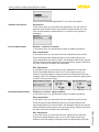
5.2 Adjustment system
1
2
1 LC display
2 Adjustment keys
Key functions
12
•
[OK] key:
–– Move to the menu overview
VEGAFLEX 81 • Foundation Fieldbus
47582-EN-140324
Fig. 9: Display and adjustment elements
5 Set up with the display and adjustment module
•
•
•
–– Confirm selected menu
–– Edit parameter
–– Save value
[->] key:
–– Presentation, change measured value
–– Select list entry
–– Select editing position
[+] key:
–– Change value of the parameter
[ESC] key:
–– Interrupt input
–– Jump to next higher menu
Adjustment system
The sensor is adjusted via the four keys of the display and adjustment module. The LC display indicates the individual menu items. The
functions of the individual keys are shown in the above illustration.
Approx. 10 minutes after the last pressing of a key, an automatic reset
to measured value indication is triggered. Any values not confirmed
with [OK] will not be saved.
Switch-on phase
After switching on, the VEGAFLEX 81 carries out a short self-test
where the device software is checked.
The output signal transmits a fault signal during the switch-on phase.
The following information is displayed on the display and adjustment
module during the startup procedure:
•
•
•
•
Measured value indication
Instrument type
Device name
Software version (SW-Ver)
Hardware version (HW-Ver)
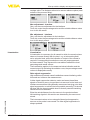
With the [->] key you can move between three different indication
modes.
In the first view, the selected measured value is displayed in large
digits.
In the second view, the selected measured value and a corresponding bar graph presentation are displayed.
47582-EN-140324
In the third view, the selected measured value as well as a second
selectable value, e.g. the temperature, are displayed.
Quick setup
5.3 Parameter adjustment - Quick setup
To quickly and easily adapt the sensor to the application, select
the menu item "Quick setup" in the start graphic on the display and
adjustment module.
VEGAFLEX 81 • Foundation Fieldbus
13
5 Set up with the display and adjustment module
You can find "Extended adjustment" in the next sub-chapter.
General information
Application
In this menu item, you can select the application. You can choose
between level measurement and interface measurement. You can
also choose between measurement in a vessel or in a bypass or
standpipe.
Level measurement
Medium - dielectric constant
In this menu item, you can define the type of medium (product).
Max. adjustment
In this menu item, you can enter the max. adjustment for the level.
Enter the appropriate distance value in m (corresponding to the
percentage value) for the full vessel. The distance refers to the sensor
reference plane (seal surface of the process fitting). Keep in mind that
the max. level must lie below the dead band.
Min. adjustment
In this menu item, you can enter the min. adjustment for the level.
Enter the suitable distance value in m for the empty vessel (e.g.
distance from the flange to the probe end) corresponding to the percentage value. The distance refers tot he sensor reference plane (seal
surface of the process fitting).
Interface measurement
Dielectric constant - upper medium
In this menu item, you can define the type of medium (product).
Max. adjustment
In this menu item, you can enter the max. adjustment for the level.
Enter the appropriate distance value in m (corresponding to the
percentage value) for the full vessel. The distance refers to the sensor
reference plane (seal surface of the process fitting). Keep in mind that
the max. level must lie below the dead band.
Enter the suitable distance value in m for the empty vessel (e.g.
distance from the flange to the probe end) corresponding to the per14
VEGAFLEX 81 • Foundation Fieldbus
47582-EN-140324
Min. adjustment
In this menu item, you can enter the min. adjustment for the level.
5 Set up with the display and adjustment module
centage value. The distance refers tot he sensor reference plane (seal
surface of the process fitting).
Max. adjustment - Interface
Carry out the max. adjustment for the interface.
To do this, enter the percentage value and the suitable distance value
in m for the full vessel.
Min. adjustment - Interface
Carry out the min. adjustment for the interface.
To do this, enter the percentage value and the suitable distance value
in m for the empty vessel.
Linearization
Linearization
A linearization is necessary for all vessels in which the vessel volume
does not increase linearly with the level - e.g. a horizontal cylindrical or spherical tank, when the indication or output of the volume is
required. Corresponding linearization curves are preprogrammed
for these vessels. They represent the correlation between the level
percentage and vessel volume.
The linearization applies for the measured value indication and the
current output. By activating the suitable curve, the percentage vessel
volume is displayed correctly.
False signal suppression
High sockets and internal vessel installations cause interfering reflections and can influence the measurement.
A false signal suppression detects, marks and saves these false
signals so that they are no longer taken into account for the level and
interface measurement. We generally recommend carrying out a false
signal suppression to achieve the best possible accuracy. This should
be done with the lowest possible level so that all potential interfering
reflections can be detected.
Enter the actual distance from the sensor to the product surface.
47582-EN-140324
All interfering signals in this section are detected by the sensor and
stored.
The instrument carries out an automatic false signal suppression
as soon as the probe is uncovered. The false signal suppression is
always updated.
VEGAFLEX 81 • Foundation Fieldbus
15
5 Set up with the display and adjustment module
47582-EN-140324
16
VEGAFLEX 81 • Foundation Fieldbus
6 Supplement
6Supplement
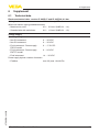
6.1
Technical data
Electromechanical data - version IP 66/IP 67 and IP 66/IP 68; 0.2 bar
Cable gland
M20 x 1.5 or ½ NPT
Wire cross-section (spring-loaded terminals)
ƲƲ Massive wire, cord
ƲƲ Stranded wire with end sleeve
Voltage supply
Operating voltage
0.2 … 2.5 mm² (AWG 24 … 14)
0.2 … 1.5 mm² (AWG 24 … 16)
ƲƲ Non-Ex instrument
9 … 32 V DC
ƲƲ Ex-ia instrument - Power supply
FISCO model
9 … 17.5 V DC
ƲƲ Non-Ex instrument
ƲƲ Ex-ia instrument - Power supply
ENTITY model
9 … 32 V DC
9 … 24 V DC
ƲƲ Ex-d instrument
14 … 32 V DC
ƲƲ Fieldbus
max. 32 (max. 10 with Ex)
47582-EN-140324
Power supply by/max. number of sensors
VEGAFLEX 81 • Foundation Fieldbus
17
Notes
47582-EN-140324
18
VEGAFLEX 81 • Foundation Fieldbus
47582-EN-140324
Notes
VEGAFLEX 81 • Foundation Fieldbus
19
All statements concerning scope of delivery, application, practical use and operating conditions of the sensors and processing systems correspond to the information
available at the time of printing.
Subject to change without prior notice
© VEGA Grieshaber KG, Schiltach/Germany 2014
VEGA Grieshaber KG
Am Hohenstein 113
77761 Schiltach
Germany
Phone +49 7836 50-0
Fax +49 7836 50-201
E-mail: [email protected]
www.vega.com
47582-EN-140324
Printing date: