1
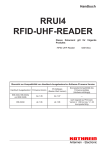
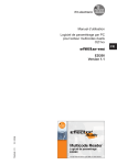
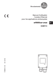
Operating instructions
RFID UHF Sensor
Mid Range
706386 / 00
12 / 2014
DTE820
UK
RFID UHF Sensor
Content
1 Preliminary note��������������������������������������������������������������������������������������������������� 3
1.1 Symbols used��������������������������������������������������������������������������������������������� 3
2 Safety instructions����������������������������������������������������������������������������������������������� 3
2.1 General������������������������������������������������������������������������������������������������������� 3
2.2 Target group ����������������������������������������������������������������������������������������������� 3
2.3 Electrical connection����������������������������������������������������������������������������������� 4
2.4 Tampering with the device��������������������������������������������������������������������������� 4
2.5 Ventilation��������������������������������������������������������������������������������������������������� 4
2.6 Environmental conditions ��������������������������������������������������������������������������� 4
2.7 Radiated electromagnetic field strengths ��������������������������������������������������� 4
3 Functions and features ��������������������������������������������������������������������������������������� 5
4 Items supplied����������������������������������������������������������������������������������������������������� 5
5 Accessories��������������������������������������������������������������������������������������������������������� 5
6 Characteristics of the antenna ��������������������������������������������������������������������������� 6
6.1 Reading range and tag shape��������������������������������������������������������������������� 6
7 Reading range and selectivity����������������������������������������������������������������������������� 7
8 Conformity with standards����������������������������������������������������������������������������������� 8
9 Installation��������������������������������������������������������������������������������������������������������� 10
9.1 Installation location����������������������������������������������������������������������������������� 10
9.2 Laying of cables ����������������������������������������������������������������������������������������11
9.3 Drilling template������������������������������������������������������������������������������������������11
9.4 Connections and status indication������������������������������������������������������������� 12
9.5 GPIO and RS-232 connection������������������������������������������������������������������� 13
9.6 Ethernet and current supply connection��������������������������������������������������� 14
10 Typical applications����������������������������������������������������������������������������������������� 15
10.1 Access systems��������������������������������������������������������������������������������������� 15
10.2 Automation industry��������������������������������������������������������������������������������� 15
10.3 Further applications��������������������������������������������������������������������������������� 15
11 Abbreviations��������������������������������������������������������������������������������������������������� 16
12 Maintenance, repair and disposal������������������������������������������������������������������� 16
2
RFID UHF Sensor
1 Preliminary note
This document is intended for specialists. These specialists are people who are
qualified by their appropriate training and their experience to see risks and to
avoid possible hazards that may be caused during operation or maintenance of
the device. The document contains information about the correct handling of the
device.
Read this document before use to familiarise yourself with operating conditions,
installation and operation. Keep this document during the entire duration of use of
the device.
UK
1.1 Symbols used
►
>
[…]
→
Instructions
Reaction, result
Designation of keys, buttons or indications
Cross-reference
Important note
Non-compliance may result in malfunction or interference.
Information
Supplementary note
2 Safety instructions
2.1 General
These instructions are an integral part of the device. They contain texts and figures
concerning the correct handling of the device and must be read before installation
or use.
Observe the operating instructions. Non-observance of the instructions, operation
which is not in accordance with use as prescribed below, wrong installation or
incorrect handling can seriously affect the safety of operators and machinery.
2.2 Target group
These instructions are intended for authorised persons according to the EMC and
low-voltage directives. The device must only be installed, connected and put into
operation by a qualified electrician.
3
RFID UHF Sensor
2.3 Electrical connection
Disconnect the device externally before handling it.
The device can be damaged when the operating voltage is switched on and no
LAN cable is connected. Connect a LAN cable to the device before you switch on
the operating voltage.
The connection pins may only be supplied with the signals indicated in the
technical data and/or on the device label and only the approved accessories of ifm
may be connected.
2.4 Tampering with the device
In case of malfunctions or uncertainties please contact the manufacturer. Any
tampering with the device can seriously affect the safety of operators and
machinery. This is not permitted and leads to the exclusion of any liability and
warranty claims.
2.5 Ventilation
During operation the device must be sufficiently ventilated. Install the device only
in places where ventilation is ensured.
With insufficient ventilation there is a risk of fire.
2.6 Environmental conditions
Do not place the device in the vicinity of heaters, do not expose it to direct sunlight
and do not operate it in wet environments. No objects with open flames must be
placed onto the device. Protect the device against moisture, falling water drops and
splashing water. Observe the environmental conditions indicated in the technical
data sheet.
There is a risk of fire in unsuitable environmental conditions.
2.7 Radiated electromagnetic field strengths
The device complies with the requirements to CE.
Brand name:
ifm electronic DTE820 RFID-UHF sensor for Europe
The DTE820 is designed for operation in accordance with EN 302208. During
operation the human exposure regulations to EN50364 have to be observed.
Ensure a minimum distance of 23 cm between antenna and human bodies.
During operation cardiac pacemakers of people in the vicinity may be impaired.
In case of doubt, persons concerned should consult the manufacturer of the
pacemaker or their doctor.
Reduce the output power of your device depending on the antenna cable
length and the antenna gain.
4
RFID UHF Sensor
3 Functions and features
The DTE820 RFID UHF sensor integrates a mid-range RFID UHF antenna and an
RFID UHF reader to process the antenna signals. The device is suited for reading
and writing active and passive RFID tags in the frequency range of 865 - 868 MHz.
The DTE820 has a PoE Ethernet interface and a serial interface. In addition digital
inputs and outputs (GPIO) are available. The device can be supplied with voltage
either via PoE or locally.
On delivery the device can read and write tags according to the EPC Gen2
standard. Other protocols can be uploaded via software updates.
UK
Knowledge of the EPCglobal GS1 standard is necessary for the configuration of
the DTE820. In this standard the function of the interface between tag and reader
is described. Further information at: www.epcglobalinc.org.
The DTE820 can be controlled and evaluated in various ways:
●● Software ReaderStart
●● Supplied DLL
●● Access to the reader protocol
4 Items supplied
●● DTE820 RFID UHF sensor
●● CD with demo software, example programming, DLL and documentation
5 Accessories
The following accessories are available for the DTE820: If you have any questions
about the accessories, please contact our sales team.
●● Connection cable for Ethernet and current connection (PoE), article no. E11898
●● Mast and wall fixture, article no. E80340 for mounting RFID antennas,
DTE readers and sensors (up to a total weight of 6.0 kg).
●● Connection cable for GPIO and RS-232 connection, 12 poles,
article no. for 1.5 m ZB0643, article no. for 5.0 m: ZB0656.
5
RFID UHF Sensor
6 Characteristics of the antenna
The RFID UHF antenna integrated in the DTE820 is a mid-range antenna which
meets the requirements of many RFID applications.
Mid-range antennas have been developed for applications in the near and far
field. Special attention was paid to a small design for integration in compact
environments. For dimensions of 156 x 126 reading ranges of more than 2 m are
nevertheless possible. Mid-range antennas also have an increased selectivity at
lower read distances as compared to conventional antennas. That means that they
are suitable for the transition range with various tags.
6.1 Reading range and tag shape
Reading range
Tag shape
loop-shaped
hybrid-type
dipole-type
10-30 cm
30 - 100 cm
> 100 cm
The correct combination of antenna and tag is essential for every RFID
application. This ensures a high reading rate and reliable system operation.
2m
1m
DTE820 100° 30 ERP
4m
2m
Figure: DTE820 reading range
6
0
2m
4m
RFID UHF Sensor
7 Reading range and selectivity
The reading range and the selectivity are the most important features of an RFID
application. The reading range describes the greatest distance at which a tag
can be read. The selectivity indicates the required minimum distance for clear
distinction between two adjacent tags.
The system features depend considerably on the tag type used.
In general, the UHF RFID tags can be divided into three groups:
The first group consists of small, loop-shaped tags (near field tags) with an
average diameter of 2 cm that mostly couple with the antenna magnetically. These
tags have the smallest ranges since the magnetic field decreases rapidly with the
distance of the antenna.
The second group consists of hybrid-type tags which are a mix of loop-shaped
and dipole-type tags. These tags can be activated by the antenna via the magnetic
field, the electric field or a combination of both.
The third group is made up of dipole-type tags (far field tags) which mostly couple
via the electric field. Ranges of more than 10 m are possible.
Reading range
Selectivity
Figure: RFID UHF sensor detects tag at short
distance
Figure: Illustration of reading range and selectivity
7
UK
RFID UHF Sensor
8 Conformity with standards
Since the RFID systems are radio systems, they are in the scope of the 1999/5/EC
guideline of the European Commission (Radio and Telecommunications Terminal
Equipment R&TTE).
As evidence of the conformity with the basic requirements of this guideline there is
a number of harmonised standards that are published in the Official Journal of the
European Union.
The ifm antennas have a passive antenna structure. The system integrator is
responsible for meeting the standards. Therefore it is expressly recommended to
acquire these standards.
Two important standards in connection with antennas are (not exhaustive)
EN 302208 and EN 50364: The first one deals with radio spectrum matters and
limits the maximally radiated power while
EN 50364 deals with the limitation of human exposure to electromagnetic fields.
As evidence of the antenna conformity with the standard EN 50364 the specific
absorption rate (SAR) is calculated numerically. The determined SAR values are
compared with the basic limit values of EN 50364 - classified to occupational
exposure, exposure of the general public and local exposure of head and
trunk and limbs. The WiRa is in general used for applications with a reading
area starting with 20 cm. At this distance the values are significantly below the
maximum SAR values permitted by law. In case that use is intended for smaller
distances, the respective SAR values are numerically calculated. The assumptions
taken as basis (such as operating mode of the RFID system and characteristics
of the human tissue) ensure a conservative estimate of the exposure (worst case
scenario).
The calculation was also made for the most sensitive constellation
i.e. for the case that members of the general public stay permanently in direct
vicinity of the antenna with their head or trunk.
If the distance between the person and the antenna is less than 3 cm, the
DTE820 ensures that the maximally allowed SAR is not reached with an antenna
input power of up to 0.34 W (25.31 dBm). In all other cases the DTE820 can be
operated with the maximally radiated power of 0.5 W ERP (27 dBm) or an antenna
input power of 0.653 W (28.15 dBm). The table below shows the maximum
input powers with which the antenna may be supplied to ensure that the basic
limit values of the SAR are not exceeded. Two different types of exposure are
differentiated:
8
RFID UHF Sensor
Max. input power
General public
Limit values head and trunk 2 W/kg
Limit values local limbs 4 W/kg
Occupational exposure
Limit values head and trunk 10 W/kg
Occupational exposure
Limit values local limbs 20 W/kg
Distance person
and DTE820 <
1 cm
1 cm < distance
person and
DTE820 < 7 cm
Pin = 0.32 W
Pin = 1.75 W
7 cm < distance
person and
DTE820
Pin = 1.84 W
Pin = 1.84 W
Pin = 1.84 W
UK
9
RFID UHF Sensor
9 Installation
9.1 Installation location
The operating principle of the antenna is influenced by the type of installation and
the environment.
Observe the following remarks for the selection of the installation location:
●● Keep a distance of min. 70 cm to metal surfaces and the ground (see Figure 1).
●● When installed in front of a metal surface, use a mounting bracket that
establishes a distance of exactly 12 cm between the back of the device and the
metal surface (see Figure 2).
●● With direct installation on a metal surface (e.g. a plate as part of
a mounting bracket) use a square-shaped metal plate with the dimensions
16 x 16 cm (see Figure 3).
●● Avoid conductive objects such as tanks with liquids in the vicinity of the
installation location. The objects influence the performance of the antenna.
min 70 cm
●● Ensure sufficient heat dissipation at the installation location. The maximum
operating temperature indicated in the data sheet must not be exceeded.
12 cm
min 70 cm
min 70 cm
min 70 cm
max 16 cm
max 16 cm
Figure 1: Distance to all sides min. 70 cm
Figure 2: Distance
between device and
metal surface
exactly 12 cm
Figure 3:
Metal surface with
max. 16 cm x 16 cm
If the installation instructions are not adhered to, the antenna characteristics
change. The DETE820 must be newly assessed at the mounting location.
10
RFID UHF Sensor
9.2 Laying of cables
Observe the following notes when laying the cables:
●● Lay the cables vertically and straight away from the sensor
(see figure on the right).
●● Avoid cable loops around and on the sensor (see figure on the left).
UK
X
Figure: Incorrectly laid cable
Figure: Correctly laid cable
9.3 Drilling template
The DTE820 is fixed to the ground using 4 screws. The bore hole distances are
indicated in the following drawing. A fixture allowing installation on a mast is
available as accessory.
4,5
110
140
11
RFID UHF Sensor
9.4 Connections and status indication
The DTE820 is controlled and evaluated via two connections and a status
indication. The following sections describe the connections and the status
indication.
1
2
3
1 GPIO and RS-232 connection, M12 female, 12 poles
2 Status indication, 2-colour LED (red, green)
3 Ethernet and current supply connection, M12 female, 4 poles, D-coded
Load digital inputs and outputs with max. 0.5 A.
Load all digital inputs and outputs used with max. 1.5 A in total.
When using the auxiliary voltage (24 V DC, pin7), load the digital
inputs and outputs with max. 1.1 A.
Load digital inputs and outputs with max. 30 V DC.
Use LPS (Limits Power Source) or NEC class 2 power supplies as external
voltage source.
Observe the additional notes in the data sheet.
12
RFID UHF Sensor
9.5 GPIO and RS-232 connection
The 12-pole M12 socket of the DTE820 provides the digital inputs and outputs
(GPIO) and the serial interface.
9
8
12
1 10 2
7 6 5
3
4
11
Pin
Connection
1
GPIO - OUT3
2
GPIO - GND
3
GND
4
RS-232 - GND
5
RS-232 - RxD
6
RS-232 - TxD
7
24 V DC
8
GPIO - OUT2
9
GPIO - IN3
10
GPIO - OUT1
11
GPIO - IN2
12
GPIO - IN1
UK
The digital inputs are not electrically isolated from the operating voltage of the
DTE820. The DTE820 is operated with its own voltage supply.
DTE
+UB
+UB
INPUT 1
INPUT 2
INPUT 3
INPUT 1
INPUT 2
INPUT 3
GND
GND
Non-electrically isolated circuit of the inputs
13
RFID UHF Sensor
The digital outputs are not electrically isolated from the operating voltage of the
DTE820.
DTE
+UB
+UB
OUTPUT 1
OUTPUT 1
OUTPUT 2
OUTPUT 2
OUTPUT 3
GND
OUTPUT 3
GND
Non-electrically isolated circuit of the outputs
9.6 Ethernet and current supply connection
The DTE820 is connected to the Ethernet via the 4-pole M12 socket (D-coded)
and supplied with current. The current is supplied with PoE (Power over Ethernet).
1
4
2
3
Pin
Connection
1
TD+ PoE 1
2
RD+ PoE 2
3
TD- PoE 1
4
RD- PoE 2
Observe the following remarks:
●● Use a power supply with power limitation for the operation. The power supply
must not exceed 100 W on the secondary side.
●● Use screened cables. Data transfer via Ethernet with unscreened cables is
susceptible to interference.
9.7 LED
The operating states of the DTE820 are indicated via a 2-colour LED. The
following table explains possible operating states:
Operating status
Green
Red
Normal operation
Lights permanently
Flashes approx. every
8 seconds
Device booting
Lights permanently
Lights permanently
Error during booting
Flashes approx. every
8 seconds
Lights permanently
14
RFID UHF Sensor
10 Typical applications
10.1 Access systems
Due to the large reading area of UHF antennas applications for access systems
had been implemented via HF RFID so far. The new UHF RFID devices from ifm
now allow these applications as well.
For access systems such as ski lifts, buses and trains the DTE820 with integrated
mid-range antenna is recommended. That means that tickets can now be checked
at medium distance.
10.2 Automation industry
The DTE820 can be used for RFID automation applications with a defined reading
area and high selectivity. Of great advantage is the possibility to detect far-field
tags with the ANT805 antenna individually and to read the same tags with DTE820
at other reading stations at larger distances in multi-tag operation.
10.3 Further applications
Further typical applications for DTE820:
●● Logistics applications when installed on autonomous industrial transport
systems
●● Conveyor technology applications
●● Gate applications for detecting goods
●● Bulk and single tag applications
For use of the DTE820 note the effective national regulations and the
standards and guidelines valid for the application location.
15
UK
RFID UHF Sensor
11 Abbreviations
Abbreviations used in the brief instructions:
EN
ERP
European standard
Effective Radiated Power
RFID
Radio Frequency Identification
SAR
Specific Absorption Rate
UHF
Ultra High Frequency
12 Maintenance, repair and disposal
The device does not contain any components that need to be maintained.
►► Do not open the device.
►► The device must only be repaired by the manufacturer.
►► Dispose of the device in accordance with the national environmental
regulations.
16