1
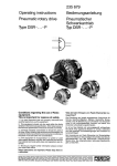
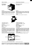
219283
FESTO
PNEUMAl-lC
Ad&de Athw A u c k l a n d B a r c e l o n a B a n g k o k Bela Hor~zonte Blmxngham B o l o g n a B o r d e a u x Brisbane Bwxelles B u d a p e s t B u e n o s Acres Campmas C a p e T o w n
Celle Delft Dublfr Duncanv~lle D u r b a n Eibar Elndhoven F~renze Fukurol Goteborg Graz G u a d a l a j a r a Hels!nkl H o n g K o n g Istanbul J a k a r t a Jo~nv~lle J o h a n n e s b u r g
Ka~ro Karlskrona Kobenhavn Ku& Lumper L e e d s L~lle Lima Ltsboa Locamo L o n d o n L y o n M a d r i d
Malmo Manila M e l b o u r n e Mwco City M~lano Monterrey
Nagoya-City Nantes O s l o Padova Paws P e r t h Port E l i z a b e t h Port0 Port Washtngton Porte Alegre Praha Pretoria Puerto RICO QUIIO FiexdalefO,&wo RIO d e
Jarxwo Roma San J o s e Sao Paula Sarreguemmes Seoul S i n g a p o r e So& S t o c k h o l m S y d n e y Tapped T e h e r a n T o k y o Valenc~a Warszawa Wren Yverdon Zurich
Operating Instructions
for pneumatic feed units
type BV-50- 40, BV-50-100
For short strokes and fast working cycles, e.g. on
high-speed presses in mass production in the precision, electrical, and watchmaking industries.
Feed units can be used to push in front of the tool or
to pull behind the tool, operating from right to left
in each case. Proper functioning is ensured in each
mounting position.
The housing of the feed unit has 4 fastening holes (10)
and is attached on the press table with socket head
cap screws to the tool or to an attachment angle. It
is advisable to attach the unit such that it can be vertically adjusted in order that the strip entry can at all
times be adjusted to the tool.
Material adjustment
With strips less than 30 mm wide, it must be ensured
that the strip is guided over the centre of the clamping piston (18) and is aligned with the tool centre. A
marking groove on the clamping gripper indicates the
centre of the clamping plate. The guide rollers (1)
are provided for lateral guidance and must be set to
the appropriate strip width. Make sure that they run
freely. With open clamping grippers, it is possible to
transport material which exceeds the width of the
feed unit.
Feed setting
Slacken clamping screws (8), turn set screw (4) until
the distance between stop (5) and feed brace corresponds to the desired feed length. Retighten clamping screws.
Insert strip
Close hand slide valve (Figs. 1 and 2, item 22), the
unit is now exhausted - insert strip - reopen hand
slide valve.
If strip or tape material is to be inserted against the
length stop, it is advisable to incorporate a further
hand slide valve into line P 1 for exhausting the grippers (Figs. 1 and 2, item 25).
Item Name
I
2
:
1:
;A
Y
Centre m a r k i n g
Guide roller
Stroke setting
Buffer plate
Fastening screw
Clamping screw for stroke setting
Guide column
Fastening hole
Lubrication nipple
Clamping piston, replaceable
The solenoid valve (Fig. 2. item 20) obtains its reversal
pulse from an electrical limit switch.
To obtain the optimum cycling frequency, the control
line between valves 20 and 21 should not exceed
two metres in the pneumatic control (Fig. I). The
control signal for valve 20 can be obtained linearly or
rotary as required. With linear pick-up, an adjustable
control rail must be mounted on the press ram. With
press strokes over 15 mm, only rotary signal pick-up
is possible.
In general, the rotary type of signal pick-up is to be
preferred. This usually allows one to avoid resetting
of the control rail if tools are changed.
With both types of control, the timing of the pulse
output for the feed should be selected such that the
rams have wiped off and the tape is freely located in
the tool. The feed should be completed no later than
30’ after upper dead centre.
Example:
Pneumatic control
Reverse control (if feed unit is to operate in the
opposing direction)
Reversal of the feed direction and opposite starting position of the slide: interchange connections
C and D.
Reversal of feed direction with same starting position of the slide: interchange connections A and B.
Reversed starting position of the slide with same
feed direction: interchange connections A and B
and also C and D on the feed unit housing.
The grippers can be shifted through 180° such that the
opening is on the opposite side. To do this, the
socket head cap screws (7, front side) must be
slackened.
Electra-pneumatic control
Conirol elements
Item
Name
2u
Air-operated valve
solenoid valve
21
Roller lever valve
En-5&40 (100)
Pneumatfc
Electra-pneum.
control
control
VL-a-‘/a -6
MLC-0-% -9
Item
COfltWl
27
26
R-3-)/,
Hand slide valve
w-311,
30
23
SewIce u n i t
24
Solenoid valve
FRC-‘/a
31
25
MOC-3-114
(only requred w i t h
intermedIate e x h a u s t )
H a n d slide valve
w-3-1/,
( o n l y with strip or
t a p e material aqalnst
lenglh s t o p ) -
Pressure regulator
L&‘#‘,
( o n l y wth low
press”re for feed)
1
26
Tools with catch pins
Where cycling rate and ram stroke permit, it is possible to momentarily exhaust the holding grippers
with tools having catch pins (locating pin, pilots). A
solenoid valve type MOC-3-‘/4 (24) fitted in line B
and operated by means of a cam disc and a limit
switch exhausts the holding gripper as soon as the
catch pin is inserted in order that the strip can be
centered.
FR-4-‘/<
Distributor pieca
1
29
22
Ouantlty
Pneum. Electra-pneum.
Name
Quick
connector
Duck c o n n e c t o r
1
Quick
TCK-’ d-PK-6
i - 1
1
I3
2
1
QM-‘I,-‘/,
Socket joint
1
1
control
1
1
CK-‘/*-PK.6
connector
Quick c o n n e c t o r
1
]
CK-‘4.PK-4
CK-“8-PK-4
3
U-‘/d
2
1
4
’
4
3
2
I
LL
A service unit type FRC must befitted on the upstream
side of the entire control system. With this unit, the
compressed air is cleaned, regulated to constant
pressure (6 bar), and provided with a fine oil mist for
lubricating purposes. The bearing bushes of the feed
brace must be lubricated from time to time by means
of lubricating nipple (II).
Diagram showing approximate values for max. working cycies/min at 6 bar working and control pressure
BV-51S.40
TYPO
I
Material width max.
rnnl
50
Feed (infinitely variable)
mm
0 to 40
Material thickness max.
mm
1.0
Feed force at 6 bar
N
C l a m p i n g fOrCe at 6 bar
N
bar
1
I
1
kg
I
I c onnection
1 Pressure
ranoe
Weight
450
400
R ‘#‘a
3to6
I
1
.; 350
>
; 300
2
c 250
‘2
k 200
3
I
I
R ‘1~
3 to 6
3.7
1N -0Jkp
150
Permissible cross-section diagram
’ loo**
o
Values for properly flattened material with non-driven
reel up to 60 cycles/min. To achieve these values, a
driven reel must be used at higher cycling rates.
10
20
30
40
50
60
70 80
90
Stroke brn]
The attainable working cycles/min depend on many
factors, mostly stroke and load. In the diagram, the
upper range for each type represents the attainable
cycling frequency at low load, and the lower range
represents the attainable cycling frequency at high
load.
To attain the upper limit, time-leading control is advisable.
A fitted advance movement cushioning arrangement
allows optimum balancing of stroke, cycle rate, and
mass.
t
0,2
0,4
0,6
0,8
1,O
Material t h i c k n e s s [ m m ]
Pneumatic feed unit type BV-50-40, BV-50-100 (deviating dimensions in parentheses)
Gwde r o l l e r
Supply lhne f o r
‘“OVe”Tent I ” directIon A
Supply hrle f o r
holdfng grIpper
Feed gripper can be
r e l o c a t e d throuoh 160:
Supply hne for
”
Holding grIpper c a n b e
Adjustable advance
,eed gr,pper
r e l o c a t e d t h r o u g h 16OJ
m o v e m e n t cushic
S u p p l y line for
m o v e m e n t I”
dIrectIon B
Feed brace
Y I(1ller,
be tipped up
Fastentng h o l e
,y
Plug screw
ClampIng piston
replaceable
31,s
F
Protective c o v e r
,
Clamping screw for
s t r o k e setting
clamping
The information given is liable to modification without
notice