1
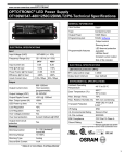
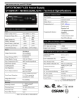
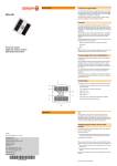
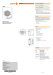
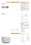
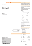
Operating instructions
I / 2010
Subject to change
OSRAM GmbH
Customer-Service-Center (CSC)
Steinerne Furt 62
86167 Augsburg, Germany
Tel. : (+49) 1803 / 677 - 200 (charges apply)
Fax.: (+49) 1803 / 677 - 202
040808EN
DMX controlled dimmer unit for RGB LED-modules
OT DMX 3x1 RGB DIM Ver. 3.0
www.osram.com
www.osram.de
General
Contents
General
Installation
Operation
Appendix
Application and function ........................................................................2
Safety information .................................................................................2
Design and dimensions .........................................................................3
Wiring diagram ......................................................................................3
System extension ..................................................................................5
General functions ..................................................................................6
Operation modes...................................................................................6
Addressing ............................................................................................6
Troubleshooting ....................................................................................7
Technical data.......................................................................................8
Application and function
The DMX protocol is established as one of the leading Lighting Management System protocol for
dynamic RGB coloured lighting applications. The dimmer OT DMX 3x1 RGB DIM unit has been
designed to be a suitable LED-module controller for a wide range of applications, when DMX protocol
is adopted. The OT DMX 3x1 RGB DIM is a 3-channel PWM LED Dimmer unit for 10 V and 24 V LEDmodules providing a DMX control interface and PWM LEDdrivers as output. It is designed especially
for RGB colormixing applications by controlling the brightness of individual LED modules.
Main applications:
• Large area effect lighting in architecture or cove lighting applications
• Colour light effects and design-oriented lighting as creative element in discotheques, theatres,
concerts etc.
Main control unit advantages:
• Full dimming range 0 −100%
• Protection class II
• Auto-reset in case of open-circuit, overload and over temperature
• Short circuit protection in combination with OPTOTRONIC power supply
• Compliance with all relevant lighting standards
Safety information
The following information is provided for your safety:
• Please read these operating instructions carefully before installing and using the OT DMX 3x1
RGB DIM (referred as OT DMX 3x1 later on in the document). This is the only way to ensure
that you use the equipment safely and correctly. Keep these operating instructions in a safe
place for future reference. You should make sure that everyone who uses OT DMX 3x1 has
read these operating instructions.
• OT DMX 3x1 may only be installed by qualified personnel who have been appropriately trained
and who have the relevant authority. The installation personnel must be familiar with the
operating instructions. Mains power must be disconnected before performing any changes in
the electrical installation.
• The relevant safety and accident prevention regulations must be observed.
• If the control cable or switch input is wired with external voltage, particularly with a mains
voltage of 230 V, the unit may be destroyed.
OSRAM operating instructions: OT DMX 3x1 RGB DIM
Page2
Installation
Design and dimensions
Geometry (l x w x h): 80 mm x 40 mm x 22 mm
Wiring diagram
L
N
OT Converter
constant
voltage
+
-
10-24V
DC in
+
-
10-24 V
L
N
+
R-
OT DMX 3X1
RGB DIM
Shield
1)
DMX
Controller 2)
DMX in
D+
D-
+
R
G
B
RGB LED
module
GB-
Note 1: Shield is common transmitter ground and
must not be PE referenced in DMX controller
Note 2: for instance OSRAM EASY DMX SO
Fig. 1: DMX LED-System - OT Electronic Control Gear for LED Modules and OT DMX 3x1 RGB
DIM.
Wiring
• Maximum output cable length is limited by EMI and depending on OPTOTRONIC power supply.
The max. output cable length of the power supply has to be observed.
• Control interface (DMX) is not isolated from the input and output terminal, so only the
connection of an unearthed SELV DMX control signal is allowed.
Connecting OT DMX 3x1 RGB DIM to constant voltage power supplies
• The OT DMX 3x1 RGB DIM is placed between the OPTOTRONIC power supply and the LEDmodule.
• Only 10V and 24V LED modules and power supplies are specified for the OT DMX 3x1 RGB
DIM.
• The faultless operation of OT DMX 3x1 RGB DIM is only warranted with the OPTOTRONIC
power supplies for 10 V and 24 V. Operation with constant current power supplies or batteries
is not allowed.
• Operating voltage and power consumption of LED-Modules have to correspond with the OT’s
rated values.
Connecting OT DMX 3x1 RGB DIM to the LED-modules
• Ensure that the LED modules rated value corresponds with the output voltage of the
OPTOTRONIC power supply.
• Do not exceed a LED power consumption of 10 W for 10 V supply or 24 W for 24 V supply per
output channel.
Page 3
OSRAM operating instructions: OT DMX 3x1 RGB DIM
Installation
Environment protection
Maximum permissible ambient temperature (50°C) must not be exceeded. Ensure there is
adequate space or ventilation to keep ambient temperature ≤ 50°C. In critical installations the
temperature at tc has to be checked
Wire stripping
A = 12 mm, B = 7 mm
General note:
The luminaire manufacturer is responsible for providing the required clearances and creepage
distances and also for the protection against electrical shock, especially for the line and load wires.
OSRAM operating instructions: OT DMX 3x1 RGB DIM
Page 4
Installation
System extension
10-24
V
10-24
V
10-24
V
Figure 2: DMX LED-System - System expansion
An expansion of the system can be implemented by connecting the insulated DMX control line to
the next OT DMX 3x1 RGB DIM device and so on.
Page 5
OSRAM operating instructions: OT DMX 3x1 RGB DIM
Operation
General functions
The OT DMX 3x1 RGB DIM unit is completely driven by means of DMX input signal. Therefore a
DMX signal is control unit is required.
By means of DMX signal, the unit performs the following:
• Individual mixing of colours of the LED modules by means of pulse-width modulation
• Fast colour changing sequences allowed by a very fast dimming characteristic
• Full dimming range 0 −100%
Operation modes
Two different modes of operation are permitted. Modes are selected via DIP switch settings (see
Addressing section for further details):
• Normal operation: DIP switch 10 should always be Off (↓) for normal operation.
• Test mode: DIP switch 10 shall be ON (↑). As consequence the OT DMX 3x1 RGB DIM runs in
test mode.
Addressing
The DMX addresses can be set via DIP switches 1…9, located on the device bottom side. The set
DMX address is for the RED-channel. The GREEN- and BLUE-channel will be addressed
consecutively, e.g. set DMX address 001 RED-channel: address 001; GREEN-channel:
address 002 and BLUE-channel: address 003.
ON = ↑
Dip switch
OFF = ↓
Dip switch
pin setting
DMX Addressing via DIP switches
To use the DMX addressing table, first find the DMX address in the main block of the table. Then
read the settings for pins 1 – 5 in the first column to the left and read the settings for pins 6 - 9
above the address.
For example, to set the DMX address to 365, you need to set DIP switch pins 1, 3,4 and 6,7, 9 to
ON, as highlighted in the table.
OSRAM operating instructions: OT DMX 3x1 RGB DIM
Page 6
Operation
6789
12345
↓↓↓↓↓
↑↓↓↓↓
↓↑↓↓↓
↑↑↓↓↓
↓↓↑↓↓
↑↓↑↓↓
↓↑↑↓↓
↑↑↑↓↓
↓↓↓↑↓
↑↓↓↑↓
↓↑↓↑↓
↑↑↓↑↓
↓↓↑↑↓
↑↓↑↑↓
↓↑↑↑↓
↑↑↑↑↓
↓↓↓↓↑
↑↓↓↓↑
↓↑↓↓↑
↑↑↓↓↑
↓↓↑↓↑
↑↓↑↓↑
↓↑↑↓↑
↑↑↑↓↑
↓↓↓↑↑
↑↓↓↑↑
↓↑↓↑↑
↑↑↓↑↑
↓↓↑↑↑
↑↓↑↑↑
↓↑↑↑↑
↑↑↑↑↑
↓↓↓↓ ↑↓↓↓ ↓↑↓↓ ↑↑↓↓ ↓↓↑↓ ↑↓↑↓ ↓↑↑↓ ↑↑↑↓ ↓↓↓↑ ↑↓↓↑ ↓↑↓↑ ↑↑↓↑ ↓↓↑↑ ↑↓↑↑ ↓↑↑↑ ↑↑↑↑
1
2
3
4
5
6
7
8
9
10
11
12
13
14
15
16
17
18
19
20
21
22
23
24
25
26
27
28
29
30
31
32
33
34
35
36
37
38
39
40
41
42
43
44
45
46
47
48
49
50
51
52
53
54
55
56
57
58
59
60
61
62
63
64
65
66
67
68
69
70
71
72
73
74
75
76
77
78
79
80
81
82
83
84
85
86
87
88
89
90
91
92
93
94
95
96
97
98
99
100
101
102
103
104
105
106
107
108
109
110
111
112
113
114
115
116
117
118
119
120
121
122
123
124
125
126
127
128
129
130
131
132
133
134
135
136
137
138
139
140
141
142
143
144
145
146
147
148
149
150
151
152
153
154
155
156
157
158
159
160
161
162
163
164
165
166
167
168
169
170
171
172
173
174
175
176
177
178
179
180
181
182
183
184
185
186
187
188
189
190
191
192
193
194
195
196
197
198
199
200
201
202
203
204
205
206
207
208
209
210
211
212
213
214
215
216
217
218
219
220
221
222
223
224
225
226
227
228
229
230
231
232
233
234
235
236
237
238
239
240
241
242
243
244
245
246
247
248
249
250
251
252
253
254
255
256
257
258
259
260
261
262
263
264
265
266
267
268
269
270
271
272
273
274
275
276
277
278
279
280
281
282
283
284
285
286
287
288
289
290
291
292
293
294
295
296
297
298
299
300
301
302
303
304
305
306
307
308
309
310
311
312
313
314
315
316
317
318
319
320
321
322
323
324
325
326
327
328
329
330
331
332
333
334
335
336
337
338
339
340
341
342
343
344
345
346
347
348
349
350
351
352
353
354
355
356
357
358
359
360
361
362
363
364
365
366
367
368
369
370
371
372
373
374
375
376
377
378
379
380
381
382
383
384
385
386
387
388
389
390
391
392
393
394
395
396
397
398
399
400
401
402
403
404
405
406
407
408
409
410
411
412
413
414
415
416
417
418
419
420
421
422
423
424
425
426
427
428
429
430
431
432
433
434
435
436
437
438
439
440
441
442
443
444
445
446
447
448
449
450
451
452
453
454
455
456
457
458
459
460
461
462
463
464
465
466
467
468
469
470
471
472
473
474
475
476
477
478
479
480
481
482
483
484
485
486
487
488
489
490
491
492
493
494
495
496
497
498
499
500
501
502
503
504
505
506
507
508
509
510
511
Table 1. DMX address settings
Note that:
o
Address 000: not used
o
Addresses 511 and 512 can’t be set, due to missing addresses for following GREEN and
BLUE channel, e.g. 511 RED: 511; GREEN: 512; BLUE: no continuing address existing !
o
DIP switch 10 should always be Off (↓) for normal operation.
o
Test mode: DIP switch 10: ON (↑)
Troubleshooting
The LED system is not working. Possible cause:
• There is no power.
• The LED module is faulty.
Replace them.
• The LED modules are off.
Check the wiring connection correctness or run in test mode
Page 7
OSRAM operating instructions: OT DMX 3x1 RGB DIM
Appendix
Technical data
Designation:
OT DMX 3x1 RGB DIM
For LED modules:
With respect to the output conditions:
LINEARlight Colormix; LINEARlight Colormix Flex, COINlight Colormix,
DRAGONchain Colormix, LINEARlight-DRAGON Colormix and other
appropriate modules
Supply input voltage
range nom.:
10,5 - 24 V DC
Supply input voltage
range min - max:
8,5…25 V DC
Power losses:
1,5 W
Control signal:
DMX (SELV equivalent) acc. USITT DMX-512A, DMX512 (DIN 56930-2)
Electrical specification:
ANSI/TIA/EIA-485-A-1998
Galvanic separation:
No, SELV required (acc. to EIA-485)
Control signal range:
-7…+12VDC, (without damage to the device)
Dimming modus:
PWM
Dimming range:
0…100%
Dimming curve:
approximate to EN 60929:2004 E.4.3.7
Output current max:
1 A for each channel
Output load range:
0 - 10 W per channel @ 10,5 V DC / 0 - 24 W per channel @ 24 V DC
Normative references:
EN 55015, IEC 61347, EN 61547
Protection class:
II
Protection type:
IP 20
Ambient temperature
range:
-20 °C to +50 °C
No-load proof:
Yes
Short circuit protection:
Yes, electrically reversible for each channel
Overload protection:
Yes, electrically reversible for each channel
Over temperature
protection:
Yes, reversible
Wire cross section for
push in terminals:
0,5 mm² to 1.5 mm² massive leads
0,75 mm² to 1 mm² flexible leads
Max. cable length:
10 m with 1.5 mm² massive leads
Geometry (l x w x h):
80 mm x 40 mm x 22 mm
Approvals:
The CE symbol signifies compliance with the relevant EU Directives.
OSRAM operating instructions: OT DMX 3x1 RGB DIM
Page 8