1
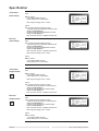
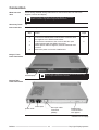
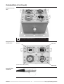
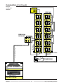
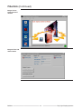
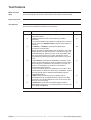
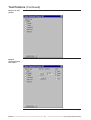
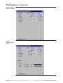
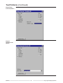
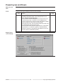
BARCO DAYLIGHT DISPLAY SYSTEMS LD FiberLink Systems LD LD R9850190 R9850200 R9850460 R9850470 Transmitter Receiver Transmitter Receiver (Multi-Mode) (Multi-Mode) (Single Mode) (Single Mode) INSTALLATION MANUAL Date: 27/11/2000 Rev: 02 Art. No: R5976160 Due to constant research, the information in this manual is subject to change without notice Trademarks are the rights of their respective owners All rights reserved Produced by BARCO NV, 27/11/2000 BARCO n.v./Daylight Display Systems Noordlaan 5 B-8520 Kuurne Belgium Tel : +32/56/368828 Fax : +32/56/368824 e-mail: [email protected] Visit Barco on the web: http://www.barco.com Printed in Belgium Contents Order Numbers ...................................................... 4 Ordering spare/ replacement parts ............................................................... 4 Safety Guide Lines ................................................ 5 Safety guide lines .......................................................................................... 5 Personnel ............................................................................................... 5 Caution .................................................................................................. 5 Product Care .......................................................................................... 5 Safety Notice .......................................................... 6 IMPORTANT WARNINGS ............................................................................. 6 Risk of electric shock ............................................................................ 6 Maximum ambient temperature ........................................................... 6 Risk of personnel injury ........................................................................ 6 Flammable materials ............................................................................ 6 Risk of electric shock/ Risk of fire ......................................................... 6 Disconnect device ................................................................................ 6 This equipment must be earthed ......................................................... 6 Power system ....................................................................................... 6 Mains cords .......................................................................................... 6 CLASS 1 LASER PRODUCT .............................................................. 6 Service Safety Precautions ................................... 7 IMPORTANT WARNINGS ............................................................................. 7 Power Requirements ............................................................................ 7 Warning ................................................................................................ 7 Ventilation ............................................................................................. 7 Federal Communication Commission (FCC Statement) ..................... 7 Notice on Safety ................................................................................... 7 Notice on Owner's manual ................................................................... 7 Owners Record: ................................................................................... 7 On safety .............................................................................................. 7 FURTHER IMPORTANT WARNINGS .......................................................... 8 Notice on installation ............................................................................ 8 Notice on servicing ............................................................................... 8 Replacement parts ............................................................................... 8 Safety check ......................................................................................... 8 Notice on cleaning ................................................................................ 8 Specification .......................................................... 9 Transmitter ..................................................................................................... 9 (multi mode) ................................................................................................... 9 Receiver ......................................................................................................... 9 (multi mode) ................................................................................................... 9 Transmitter ..................................................................................................... 9 (single mode) ................................................................................................. 9 Receiver ......................................................................................................... 9 (single mode) ................................................................................................. 9 Connection ........................................................... 10 What has to be done ................................................................................... 10 Necessary Tools .......................................................................................... 10 Interconnection ............................................................................................ 10 Image 1 Front Panel Transmitter ......................................................... 10 Image 2 Rear Panel Transmitter ......................................................... 10 Image 3 Receiver unit .......................................................................... 11 Image 4 Receiver connections ............................................................ 11 Image 5 LEMO connector ................................................................... 11 Image 6 Connection diagram .............................................................. 12 Fiberlink ............................................................... 13 Introduction .................................................................................................. 13 Technical description Transmitter ................................................................ 13 Getting Started ............................................................................................ 13 Image 1 DLite System Control window ............................................... 14 Image 2 Fiber link main window .......................................................... 14 Test Patterns ........................................................ 15 What has to be done ................................................................................... 15 Necessary Tools .......................................................................................... 15 Test Patterns ................................................................................................ 15 Image 1 No test pattern ....................................................................... 16 Image 2 Horizontal ramp test pattern .................................................. 16 Image 3 Vertical ramp test pattern ...................................................... 17 Image 4 Crosshatch test pattern ......................................................... 17 Image 5 Byte level test pattern ............................................................ 18 Image 6 Multiburst test pattern ............................................................ 18 Diagnostics .......................................................... 19 What has to be done ................................................................................... 19 Diagnostics .................................................................................................. 19 Image 1 Diagnostics window ............................................................... 19 Powering Up and Down ...................................... 20 What has to be done ................................................................................... 20 Power ........................................................................................................... 20 Image 1 DLite control display .............................................................. 20 Transmitter Error Messaging .............................. 21 What has to be done ................................................................................... 21 Necessary Tools .......................................................................................... 21 Function and error messaging .................................................................... 21 Order Numbers Ordering spare/ replacement parts R9828831 ............ DIGITIZER ............................................................................... R9850420 ............ DIGITIZER ....................................................... MIXER+LVDS R9850080 ............ DIGITIZER ....................................................... 19"IP54 CASE R9850361 ............ DLITER TRUSS BEAM DUAL ................................................ R9850360 ............ DLITER TRUSS BEAM SINGLE ............................................. R9850060 ............ DLITE PC DATA CARD .......................................................... R9850050 ............ DLITE POWER/FUSE BOX .................................................... R9850350 ............ DLITE RENTING SYSTEMS ................................................... R9850070 ............ DLITE ROOTER BOX ............................................................. R9850210 ............ DATA CABLE .................................................................. 1.5M R9850270 ............ DUMMY DATA PLUG ......................................................... X2 R9850220 ............ DATA CABLE ..................................................................... 5M R9850230 ............ DATA CABLE .............................................. DIGITIZER-TILE R9850250 ............ POWER CABLE ............................................................. 4.5M R9850240 ............ POWER CABLE .............................................................. 0.6M R9850280 ............ DUMMY POWER PLUG ..................................................... X5 R9850260 ............ POWER CABLE ................................................................. 9M R9850351 ............ DIV PERIPHERALS ................................................................ R9850100 ............ DLITE AMBIENT ENVIRONMENT CONTROLLER R9850040 ............ DLITE CTRL SOFT ................................................................. R9850090 ............ DLITE LDL ............................................................................... R9004001 ............ DLITE L5 P14 VGN7 G1 ......................................................... R9004006 ............ DLITE L5 P14 VGN7 G1M ...................................................... R9004000 ............ DLITE L5 P14 VGN7 G2 ......................................................... R9004005 ............ DLITE L5 P14 VGN7 G2M ...................................................... R9004021 ............ DLITE L5 P19 VGN10 G1 ....................................................... R9004020 ............ DLITE L5 P19 VGN10 G2 ....................................................... R9004030 ............ DLITE L5 P28 .......................................................................... R9004010 ............ DLITE L5 P28 VGN14 ............................................................. R9004015 ............ DLITE L5 P28 VGN14 M ......................................................... R9850290 ............ R9850300 ............ R9850310 ............ R9850110 ............ R9850120 ............ R9850130 ............ R9850180 ............ R9850385 ............ R9850375 ............ R9850200 ............ R9850190 ............ R9850430 ............ R9850431 ............ R9850432 ............ R9850433 ............ R9850434 ............ R9850435 ............ DLITE FRONT ACCESS .................................................. P14 DLITE FRONT ACCESS .................................................. P19 DLITE FRONT ACCESS .................................................. P28 DLITE FLIGHT-CASE ............................................ BTM+TOP DLITE FLIGHT-CASE .............................................. 1 LAYER DLITE FLIGHT-CASE ................................................... 1 TILE DLITE FLIGHT-CASE ............................................ 2 RENTAL DLITER TRIM .......................................................... L1.344 M DLITER TRIM ........................................................... L0.896M FIBERLINK MEDIUM ........................................... RECEIVER FIBERLINK MEDIUM ................................... TRANSMITTER FIBER CABLE .................................................................. 50M FIBER CABLE ............................................................... 100M FIBER CABLE ............................................................... 150M FIBER CABLE ............................................................... 200M FIBER CABLE ............................................................... 250M FIBER CABLE ............................................................... 300M Safety Guide Lines Safety guide lines Personnel This installation must be performed by authorized and qualified technical personnel only. Accredited Safety Officers must ensure the safety of the site, construction, assembly, connection, use, dismantling, transport ..etc. of such safety critical systems. Caution Installation should be performed only after you are thoroughly familiar with all of the proper safety checks and installation instructions. To do otherwise increases the risk of hazards and injury to the user. Assembly parts are designed for intended use only in conjunction with BARCO Day Light Displays. Do not modify and/or replicate any component. BARCO uses specific materials and manufacturing processes in order to achieve part strength. Consult BARCO for assistance with custom applications. Always follow BARCO Installation Instructions. Contact BARCO if you should have any question regarding the safety of an application. The manufacturer assumes no liability for incorrect, inadequate, irresponsible or unsafe assembly of systems. Product Care BARCO products must be used in a manner consistent with their design and inspected on a routine basis for security, wear, deformation, corrosion and any other circumstances that may affect the performance capability of the device. BARCO recommends inspections at regular intervals for all installations and increasing in frequency for more critical installations. If a part is found to have damage, which may cause a hazard, the part must be removed for service or replaced immediately. Under no circumstances are BARCO parts repairable by anyone other than BARCO. BARCO 5 Daylight Display Systems Safety Notice IMPORTANT WARNINGS Risk of electric shock The lightning flash with an arrowhead within a triangle is intended to tell the user that parts inside this product may cause a risk of electrical shock to persons. The exclamation point within a triangle is intended to tell the user that important operating and/or servicing instructions are included in the technical documentation for this equipment. Maximum ambient temperature The maximum recommended ambient temperature for the FiberLink Transmitter and Reciever are 40° C and 50° C respectively, the minimum temperature is -20 ° C. Risk of personnel injury Secure all devices solidly. As a supplementary safeguard, and in order to protect against the risk of personnel injury, each receiver unit should be attached to the rack with fixings. Flammable materials Keep flammable materials away from the installation (such as curtains). Energy is transferred into heat. The installation should be such that the amount of air flow required for safe operation of the equipment is not compromised. Proper ventilation must be provided. Risk of electric shock/ Risk of fire Power cables and connectors on the FiberLink receiver unit have been designed with special properties for outdoor use, and resistance against ingress of water. Use only the factory recommended power cables and connectors. Using other cables and connectors may result in risk of electric shock and risk of fire. Each source cable supplying a column of Maximum 6 Display Tiles should be protected by a circuit breaker or fuses rated 16 A / 250 V and may incorporate a Single FiberLink Receiver Unit. Disconnect device When the appliance inlets of the individual units are not accessible, the socket outlets supplying the device shall be installed near the equipment and be easily accessible, or a readily accessible general disconnect device shall be incorporated in the fixed wiring. This equipment MUST be earthed In order to protect against risk of electric shock, the installation should be properly grounded. Defeating the purpose of the grounding type plug will expose you to the risk of electric shock. Power system It is recommended to use a TN-S power distribution system (a power distribution system with a separate neutral and grounding conductor) in order to avoid large ground currents loops due to voltage differences in the neutral conductor. The total electrical installation should be protected by an appropriate rated disconnect switch, circuit breakers and Ground Fault Current Interrupters. The installation shall be done according to the local electrical installation codes. In Europe special attention should be given to EN 60364, the standard for electrical installation of buildings. In Germany VDE 0100 should be adhered to. Mains cords The power cords delivered with this system have special properties for safety. They are not user serviceable. If the power cords are damaged, replace only with new ones. Never try to repair a power cord. CLASS 1 LASER PRODUCT This is a CLASS 1 LASER PROCUCT . BARCO 6 Daylight Display Systems Service Safety Precautions IMPORTANT WARNINGS Power Requirements The FiberLink transmitter is equipped with a built-in Power Supply Autoranging from 100 to 240Vac, 50 - 60 Hz. Warning To prevent fire or electrical shock, do not expose this device to rain or moisture Ventilation The FiberLink transmitter will require that air flows freely in both the bottom and top vent holes. Blocking these holes will greatly reduce the reliability of the unit and lead to the possibility of overheating. The maximum recommended ambient temperature for this equipment is 40ºC Federal Communication Commission (FCC Statement) This equipment has been tested and found to comply with the limits for a class B digital device, pursuant to Part 15 of the FCC Rules. These limits are designed to provide reasonable protection against harmful interference in a residential installation. This equipment generates, uses and can radiate radio frequency energy and, if not installed and used in accordance with the instruction manual, may cause harmful interference to radio communications. However, there is no guarantee that interference will not occur in a particular installation. If this equipment does cause harmful interference to radio or television reception, which can be determined by turning the equipment off and on, the user is encouraged to try to correct the interference by one or more of the following measures: Reorient or relocate the receiving antenna. Increase the separation between the equipment and the receiver. Connect the equipment into an outlet on a circuit different from that to which the receiver is connected. Consult the dealer or an experienced radio/TV technician for help. Notice on Safety Devices are built in accordance with the requirements of the international safety standards IEC 950 and UL 1950, which are the safety standards of information technology equipment including electrical business equipment. These safety standards impose important requirements on the use of safety critical components, materials and isolation, in order to protect the user or operator against risk of electric shock and energy hazard, and having access to live parts. Safety standards also impose limits to the internal and external temperature rises, radiation levels, mechanical stability and strength, enclosure construction and protection against the risk of fire. Simulated single fault condition testing ensures the safety of the equipment to the user even when the equipment's normal operation fails. Notice on Owner's manual Before operating your equipment please read this manual thoroughly, and retain it for future reference. Installation and preliminary adjustments should be performed by qualified BARCO personnel or authorized BARCO service dealers. Owners Record: The part number and serial number are located at the bottom of the equipment. Record these numbers in the spaces provided below. Refer to them whenever you call upon your BARCO dealer regarding this product. All the safety and operating instructions should be read before using this unit. The safety and operating instructions manual should be retained for future reference. All warnings on the equipment and in the documentation manuals should be adhered to. All instructions for operating and use of this equipment must be followed precisely. On safety This product should be operated from an AC power source (see chapter Power Up/Down). FiberLink R9850190 is provided with a power cord with CEE 7 plug plus power cord with ANSI 73.11 plug This product is equipped with a 3-wire grounding plug, a plug having a third (grounding) pin. This plug will only fit into a grounding-type power outlet. This is a safety feature. If you are unable to insert the plug into the outlet, contact your electrician to replace your obsolete outlet. Do not defeat the purpose of the grounding-type plug. WARNING FOR THE CUSTOMER: THIS APPARATUS MUST BE GROUNDED (EARTHED) via the supplied 3 conductor AC power cable (if the supplied power cable is not the correct one, consult your dealer.) To comply with EMC regulations, use only shielded cables. Do not allow anything to rest on the power cord. Do not locate this product where persons will walk on the cord. To disconnect the cord, pull it out by the plug. Never pull the cord itself. If an extension cord is used with this product, make sure that the total of the ampere ratings on the products plugged into the extension cord does not exceed the extension cord ampere rating. Also make sure that the total of all products plugged into the wall outlet does not exceed 15 amperes. Never push objects of any kind into this product through cabinet slots as they may touch dangerous voltage points or short out parts that could result in a risk of fire or electrical shock. Never spill liquid of any kind on the product. Should any liquid or solid object fall into the cabinet, unplug the set and have it checked by qualified service personnel before resuming operations. Lightning - For added protection for this video product during a lightning storm, or when it is left unattended and unused for long periods of time, unplug it from the wall outlet. This will prevent damage to the device due to lightning and AC power-line surges. continued on next page BARCO 7 Daylight Display Systems Service Safety Precautions (Continued) FURTHER IMPORTANT WARNINGS Notice on installation Do not place this device on an unstable cart, stand, or table. The device may fall, causing serious damage to it. Do not use this device near water. Slots and openings in the cabinet and the back or bottom are provided for ventilation; to ensure reliable operation of the device and to protect it from overheating, these openings must not be blocked or covered. The openings should never be blocked by placing the product on a bed, sofa, rug, or other similar surface. This product should never be placed near or over a radiator or heat register. This device should not be placed in a built-in installation or enclosure unless proper ventilation is provided. When using the unit in a multiunit rack assembly or closed assembly, the ambient temperature inside the assembly may not exceed the maximum rated ambient temperature of the FiberLink. The installation should be such that the amount of air flow required for safe operation of the equipment is not compromised. When installed in a rack, the mounting should be such that no hazardous condition is achieved due to uneven mechanical loading. When the mains switch located on the back of the FiberLink is not accessible due to rack mounting, the socket outlet supplying the rack shall be installed near the equipment and be easily accessible or a readily accessible disconnect device shall be incorporated in the fixed wiring. Notice on servicing Do not attempt to service this device yourself, as opening or removing covers may expose you to dangerous voltage potentials and risk of electric shock! Refer all servicing to qualified service personnel. Unplug this product from the wall outlet and refer servicing to qualified service personnel under the following conditions: When the power cord or plug is damaged or frayed. If liquid has been spilled into the device. If the product has been exposed to rain or water. If the product does not operate normally when the operating instructions are followed. Note: Adjust only those controls that are covered by the operating instructions since improper adjustment of the other controls may result in damage and will often require extensive work by a qualified technician to restore the product to normal operation. If the product has been dropped or the cabinet has been damaged. If the product exhibits a distinct change in performance, indicating a need for service. Replacement parts When replacement parts are required, be sure the service technician has used original BARCO replacement parts or authorized replacement parts which have the same characteristics as the BARCO original part. Unauthorized substitutions may result in degraded performance and reliability, fire, electric shock or other hazards. Unauthorized substitutions may void warranty. Safety check Upon completion of any service or repairs to this device, ask the service technician to perform safety checks to determine that the device is in proper operating condition. Notice on cleaning Unplug this product from the wall outlet before cleaning. Do not use liquid cleaners or aerosol cleaners. Use a damp cloth for cleaning. To keep the cabinet looking brand-new, periodically clean it with a soft cloth. Stubborn stains may be removed with a cloth lightly dampened with mild detergent solution. Never use strong solvents, such as thinner or benzine, or abrasive cleaners, since these will damage the cabinet. BARCO 8 Daylight Display Systems Specification Transmitter (multi mode) Inputs MDR26 connector 3 x 8 bit RGB at 32MHz pixel rate RS422 standard RX-TX communication Mains rating autoranging 100Vac 240Vac Outputs Fiber connection integrated in LEMO connector Transmitter fiber (50/125µ with HFBR 53D5 laser head) CLASS 1 LASER PRODUCT Receiver fiber (50/125µ with HFBR 53D5 laser head) CLASS 1 LASER PRODUCT Both connections maximum 1.5Gigabits/S transfer rate Receiver (multi mode) Inputs Fiber connection integrated in LEMO connector Transmitter fiber (50/125µ with HFBR 53D5 laserhead) CLASS 1 LASER PRODUCT Receiver fiber (50/125µ with HFBR 53D5 laserhead) CLASS 1 LASER PRODUCT Both connections maximum 1.5Gigabits/S transfer rate Mains rating autoranging 100Vac 240Vac Outputs MDR26 connector 3 x 8 bit RGB at 32MHz pixel rate RS422 standard RX-TX communication Transmitter (single mode) LD Inputs MDR26 connector 3 x 8 bit RGB at 32MHz pixel rate RS422 standard RX-TX communication Mains rating autoranging 100Vac 240Vac Outputs Fiber connection integrated in LEMO connector Transmitter fiber (9/125µ with HFCT 53D5 laserhead) CLASS 1 LASER PRODUCT Receiver fiber (9/125µ with HFCT 53D5 laserhead) CLASS 1 LASER PRODUCT Both connections maximum 1.5Gigabits/S transfer rate Receiver (single mode) LD Inputs Fiber connection integrated in LEMO connector Transmitter fiber (9/125µ with HFCT 53D5 laserhead) CLASS 1 LASER PRODUCT Receiver fiber (9/125µ with HFCT 53D5 laserhead) CLASS 1 LASER PRODUCT Both connections maximum 1.5Gigabits/S transfer rate Mains rating autoranging 100Vac 240Vac Outputs MDR26 connector 3 x 8 bit RGB at 32MHz pixel rate RS422 standard RX-TX communication BARCO 9 Day Light Display Systems Connection What has to be done Power linking and data linking cables have to connect the Fiber Link unit to the Digitizer, receiver and display LD Only when this label is displayed on the front of an Receiver or Transmitter Unit does it indicate a Long Distance single-mode Fiberlink Unit. Necessary Tools n/a Interconnection Follow the next procedure: Step 1 2 3 4 5 Action Image Switch off and disconnect all system units Connect the RS232 Data communication connector from the Digitizer to the Fiberlink transmitter Connect the transmitter to the receiver with fiber optic cable equipped with the LEMO connectors Attach power cables to digitizer, fiberlink transmitter and receiver. Switch the power on for each installed unit 1,2 2 5 Image 1 Front Panel Transmitter status display LD When this label is displayed on the front of the unit then this is a Long Distance single-mode Fiberlink Transmitter Image 2 Rear Panel Transmitter mains input power on/off fiber optic cable connection (LEMO) RS232 Data communication with digitizer continued on next page BARCO 10 Day Light Display Systems Connection (Continued) Image 3 Receiver unit LD Image 4 Receiver connections When this label is displayed on the front of the unit then this is a Long Distance single-mode Fiberlink Receiver power in optical data in/out (LEMO) power out data in/out Image 5 LEMO connector continued on next page BARCO 11 Day Light Display Systems Connection (Continued) DATA IN 1 POWER IN DISPLAY AEC OUT DATA IN OUT DATA POWER OUT POWER DATA OUT POWER IN POWER IN IN IN OUT OUT DATA POWER IN POWER FIBERLINK RECIEVER DATA POWER OUT DATA POWER OUT DATA (OPTIONAL) DATA DATA OUT Image 6 Connection diagram DATA DATA OUT POWER OUT POWER IN IN OUT OUT DATA IN DATA IN POWER FIRST TILE MAY BE IN ANY CORNER long distance rugged fiber optic cable IN IN POWER DATA POWER OUT IN daisy chained to all tiles LAST TILE WILL BE IN A CORNER daisy chained to maximum 6 tiles per branch POWER SOURCE CABLE OUTLETS POWER BOX MAX 12 POWER OUTPUTS PER BOX TO RECIEVER TO DISPLAY FIBERLINK TRANSMITTER DATA IN DATA OUT DIGITIZER CONTROL ROOM BARCO 12 Day Light Display Systems Fiberlink Introduction The Fiberlink is a digital fiber optic transmission system from Digitizer to DLite Display. It covers very long distances and has a very high bandwidth (1.5 GB/s). This enables the end-user for instance to setup the Digitizer in a remote control room. The fiberlink transmits not only the video signals but also the communication to the display. An extensive self-diagnose system has been implemented to display any transmission fault conditions should they arise. Technical description Transmitter The Fiberlink Medium TX unit takes in TMDS input signals at a maximum pixel rate of 40MHz, coming from the LED Wall digitizer or dedicated LED Wall pattern generator unit. The TMDS input is converted seamless into a high speed serial bit stream. This bit stream is modulated by a laser. The Fiberlink Medium TX is using a 850 nm VCSEL laser Transceiver (HFBR53D5). The connection with the Fiberlink Medium RX unit is established through a dual 50/125µ fibercable which has been ruggedized with LEMO connectors and special heavy duty fibercable. The Unit is fully controlled through RS232 commands. The TX unit is auto detected in the RS232 communication chain and can be addressed as a normal downstream device. Between RX unit and TX unit there is a internal fiber-only read-back protocol. The display on the units front continuously displays diagnostics information. This information is synthesized by the embedded controller. The low level information is provided to the embedded controllers by the systems FPGAs. The diagnostics information is also available to the remote systems software through the RS232 communication channel. Getting Started To get started, follow the next procedure: Step 1 Action Image Click on the Fiberlink button in the main window The Fiberlink Box appears. The Fiberlink Box contains a Fiberlink Transmit tab and a Fiberlink Receive tab. Selecting one of these provides the corresponding information such as address, serial number, software version, and run time in the Fiberlink Info tab. In the Fiberlink Controls tab, one can test the Fiberlink Transmitter or Receiver corresponding to your selection at the top. 1 2 continued on next page BARCO 13 Day Light Display Systems Fiberlink (Continued) Image 1 DLite System Control window Image 2 Fiber link main window BARCO 14 Day Light Display Systems Test Patterns What has to be done The Pattern Generator box allows generation of patterns for the Dlite Display. There are several test patterns to choose from and all can be tuned in different ways. Necessary Tools DLite Software Test Patterns There are several test patterns and all of them can be generated for the receiver as well as for the transmitter, follow the next procedure: Step 1 2 3 4 5 6 Action Image To bring out the Test Pattern box, push the Pattern Generator button <None> switches to the normal output (no pattern selected) To force an update of the pattern according to the selection made, push the <Update Pattern> button at the bottom of the box. <H Ramp> / <V Ramp> generates respectively a horizontal / vertical ramp. Move the ramp in H/V direction with the H Still or the V Still button. Select the desired direction - with the left, right, up and down buttons. Select the color of the test pattern with the color check boxes on the right. Change the colors periodically by switching the Roll check button in the Color Tab. <Crosshatch> generates an adjustable crosshatch. Once again, choose the direction and/ or dynamics of the pattern by scrolling the crosshatch in any direction: left, right, up, down or a combination. Choose the color with the appropriate check buttons! In the Crosshatch tab you can switch on one of the x pixel check buttons to define the width of the crosshatch. Control the foreground and the background amplitude with the appropriate sliders. <Byte Level> creates a byte level pattern with an amplitude that can be adjusted with the slider in the Byte Level tab. You can also adjust the color of the screen and put in a color scroll loop. <Multiburst> generates a multiburst pattern with an adjustable burst type of 1 to 8 bytes high/low. The color can once again be adjusted. 1 2 3,4 5 6 7 To be continued on next page. BARCO 15 Day Light Display Systems Test Patterns (Continued) Image 1 No test pattern Image 2 Horizontal ramp test pattern To be continued on next page. BARCO 16 Day Light Display Systems Test Patterns (Continued) Image 3 Vertical ramp test pattern Image 4 Crosshatch test pattern To be continued on next page. BARCO 17 Day Light Display Systems Test Patterns (Continued) Image 5 Byte level test pattern Image 6 Multiburst test pattern BARCO 18 Day Light Display Systems Diagnostics What has to be done Fiber Diagnostics, follow the next procedure: Step 1 Diagnostics Action Image To bring out the Fiber Diagnostics box, push <Fiber Diagnostics> The Fiber Diagnostics box allows diagnostics of the fiber. (same as shown on the Transmitters display) 1 Follow the next procedure: Diagnostics Error 1 Fiberlink fully operational 2 Failed to diagnose the Fiberlink due to a communication error 3 I2C errors detected 4 I2C error detected in back Altera 5 I2C error detected in front Altera 6 I2C error detected in eeprom 7 Link errors detected and local loop failed! FATAL Problem detected in receiver path of Fiberlink Possible cause 1 Bad Fiberlink 2 Failure of transmitter laser diode Problem detected in transmitter path of fiberlink Possible cause 1 Bad Fiberlink 2 Failure of transmitter laser diode 3 Failure of transmitter opto-receiver Severe problem detected Undefined error: PLEASE CONTACT YOUR VENDOR Transmitter statusbits: Statusbit 0: OK/FAILED Statusbit 1: OK/FAILED Link Ready: OK/FAILED PLL Locked: OK/FAILED Image 1 Diagnostics window To be continued on next page. BARCO 19 Day Light Display Systems Powering Up and Down What has to be done Fiber Diagnostics, follow the next procedure: Power To power down/up the display, follow the next procedure: Step 1 Action Image <Power OFF> shuts down the DLite Display and pushing the same button- now with the text <Power ON>- restarts the DLite Display. The Receiver Controls tab appears if a Fiberlink Receiver is selected at the top. In this tab, one can adjust some receiver controls in the event of lesser transmission quality. One can switch on three filters: the Horizontal Reconstruction Filter, the Vertical Reconstruction Filter and the Data Enable Reconstruction Filter. One can also choose between Synthesized or Transmitted Key Reference. In case the original or Transmitted Key Reference gets lost, a Synthesized Key Reference can be used to improve transmission quality. 1 Image 1 DLite control display BARCO 20 Day Light Display Systems Transmitter Error Messaging What has to be done The fiberlink transmitter display indicates all status and error messages Necessary Tools DLite Software Function and error messaging To understand the operation message menus, follow the next procedure: Step 1 Action Image The fibre link is continuously being checked for possible error and proper operation. The display will indicate continuously the immediate status of the fibre link. Click on the fibre link icon in the DLite Software main window. see flow chart To be continued on next page. BARCO 21 Day Light Display Systems Transmitter Error Messaging (Continued) STARTUP FIBERLINK BARCO FIBERLINK INITIALIZING SYSTEM SOFTWARE 0.01 FIRMWARE: FRONT: 1.0 BACK: 1.0 SYSTEM TEST COMPLETED SUCCESSFULLY: NO ERRORS normal startup LINK ERROR DETECTED TESTING LOCAL LOOP TRANSMITTER FATAL ERROR LOCAL LOOP TEST FAILURE link errors detected, and local loop neither; fatal error SYSTEM ERRORS DETECTED GIVING ERROR INFO: link error during startup, but local loop OK; display gives statusbit errors DATA INPUT SELECTED Statusbit 0: OK DATA INPUT SELECTED FIBERLINK OPERATIONAL DATA INPUT SELECTED NO INPUT CLOCK DETECTED DATA INPUT SELECTED NO INPUT CLOCK DETECTED DATA INPUT SELECTED Statusbit 1: OK NO INPUT CLOCK DETECTED CHECK INPUT CONNECTION SYSTEM OPERATIONAL BUT DATA ERRORS PATH RX->TX SYSTEM OPERATIONAL BUT SIGNAL MISMATCH TX-RX DATA INPUT SELECTED Linkready: OK no link errors; no input clock detected: digitizer off, or no cable between digitizer and TX-unit, or data or SDI selected with no signal input TX-unit cant read information from RX-unit; reason: probably data errors in path RX to TX & no input cable or no digitizer connected, or no input signal when SDI or data selected TX-unit detects that datasignal in RX-unit contains data-errors in comparison with transmitted datasignal; reason: probably malfunctioning transmit path link & no input cable or no digitizer connected, or no input signal when SDI or data selected DATA INPUT SELECTED FIBERLINK OPERATIONAL DATA INPUT SELECTED FIBERLINK OPERATIONAL SYSTEM OPERATIONAL BUT DATA ERRORS PATH RX->TX SYSTEM OPERATIONAL BUT SIGNAL MISMATCH TX-RX TX-unit cant read information from RX-unit; reason: probably data errors in path RX to TX TX-unit detects that datasignal in RX-unit contains data-errors in comparison with transmitted datasignal; reason: probably malfunctioning transmit path link DATA INPUT SELECTED PLL locked: OK DATA INPUT SELECTED Link error bit: OK DATA INPUT SELECTED Fiberlink operational normal operation and no errors local loop every 4 testcycles local loop every 4 testcycles local loop every 4 testcycles LINK ERROR DETECTED TESTING LOCAL LOOP LINK ERROR DETECTED TESTING LOCAL LOOP LINK ERROR DETECTED TESTING LOCAL LOOP LINK ERROR DETECTED BUT LOCAL LOOP OK LINK ERROR DETECTED BUT LOCAL LOOP OK LINK ERROR DETECTED BUT LOCAL LOOP OK LINK ERROR BECAUSE: LINK READY BIT FAIL LINK ERROR BECAUSE: STATUSBIT 1 FAIL LINK ERROR BECAUSE: LINK READY BIT FAIL LINK ERROR BECAUSE: LINK ERROR BIT SET LINK ERROR DETECTED IN TRANSMITTER PATH LINK ERROR BECAUSE: LINK ERROR BIT SET LINK ERROR BECAUSE: STATUSBIT 0 FAIL CHECKING LINK LINK ERROR BECAUSE: STATUSBIT 0 FAIL LINK ERROR BECAUSE: STATUSBIT 1 FAIL error sequence if transmitter path doesnt work reason: fiber or laserdiode RX or opto-receiver in TX fail LINK ERROR BECAUSE: STATUSBIT 1 FAIL LINK ERROR DETECTED IN RECEIVER PATH LINK ERROR DETECTED PLL NOT LOCKED CHECKING LINK CHECKING LINK error sequence if receiver path doesnt work reason: fiber or laserdiode TX fail error sequence if not a particular transmit or receive error condition BARCO 22 FATAL I2C-ERROR: LINK CHECK IMPOSSIBLE I2C-fail; nothing concerning link quality can be read Day Light Display Systems Transmitter Error Messaging (Continued) RX-UNIT IS TESTGENERATOR Pattern <pattern type> TX-UNIT IS TESTGENERATOR Pattern <pattern type> TX-UNIT IS TESTGENERATOR Pattern <pattern type> FIBERLINK OPERATIONAL SYSTEM OPERATIONAL BUT ERROR IN PATH RX TO TX FIBERLINK OPERATIONAL RX-unit works as testgenerator RX-unit works with incoming signals; no link errors detected TX-unit is testpattern generator; TX-unit cant read information from RX-unit; reason: probably data errors in path RX to TX MULTIBURST LINK QUALITY TEST: NO ERRORS DETECTED TX-UNIT IS TESTGENERATOR Pattern <pattern type> TX-UNIT IS TESTGENERATOR Pattern <pattern type> TX-UNIT IS TESTGENERATOR Pattern <pattern type> FIBERLINK OPERATIONAL SYSTEM OPERATIONAL BUT SIGNAL MISMATCH TX-RX FIBERLINK OPERATIONAL TX-unit works as testgenerator, TX-unit is testgenerator; TX-unit detects that datasignal in RX-unit contains data-errors in comparison with transmitted datasignal; reason: probably malfunctioning transmit path link BARCO 23 link control with multiburst pattern; no errors detected (same signals in RX as generated ones in TX) MULTIBURST LINK QUALITY TEST: ERRORS DETECTED link control with multiburst pattern; link errors detected (signal mismatches between TX and RX) Day Light Display Systems


![XLite ToolSet Software [v05]](http://vs1.manualzilla.com/store/data/006304861_1-6990b54c95ba147b0c6f68f733c5e98d-150x150.png)