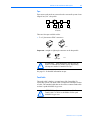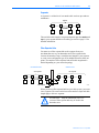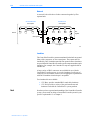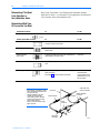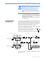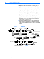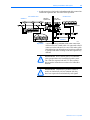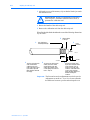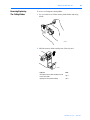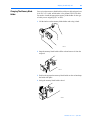
1
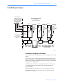
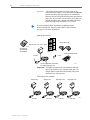
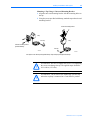
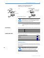
Allen-Bradley
ControlNet Ex
Media System
(Cat. No. 1797 Series)
Planning and
Installation
Manual
Important User
Information
Because of the variety of uses for the products described in this
publication, those responsible for the application and use of this control
equipment must satisfy themselves that all necessary steps have been
taken to assure that each application and use meets all performance and
safety requirements, including any applicable laws, regulations, codes
and standards.
The illustrations, charts, sample programs and layout examples shown
in this guide are intended solely for purposes of example. Since there
are many variables and requirements associated with any particular
installation, Allen-Bradley does not assume responsibility or liability
(to include intellectual property liability) for actual use based upon the
examples shown in this publication.
Allen-Bradley publication SGI-1.1, Safety Guidelines for the
Application, Installation, and Maintenance of Solid-State Control
(available from your local Allen-Bradley office), describes some
important differences between solid-state equipment and
electromechanical devices that should be taken into consideration when
applying products such as those described in this publication.
Reproduction of the contents of this copyrighted publication, in whole
or in part, without written permission of Allen-Bradley Company, Inc.,
is prohibited.
Throughout this manual we use notes to make you aware of safety
considerations:
!
ATTENTION: Identifies information about practices
or circumstances that can lead to personal injury or
death, property damage or economic loss.
Attention statements help you to:
• identify a hazard
• avoid the hazard
• recognize the consequences
Important:
Identifies information that is critical for successful
application and understanding of the product.
ControlNet is a trademark of ControlNet International Ltd.
ControlNet Ex, PLC, PLC-5/20C, and PLC-5/40C are trademarks of Rockwell Automation.
Publication 1797-6.2.1 - April 1999
Preface
About This Manual
Manual Contents
Use this manual to plan and install a ControlNet Ex™ media system.
This manual describes the required components of an intrinsically safe
cable system and how to plan for and install these required components.
This manual is specifically targeted at configuring a ControlNet Ex
system. However, since a ControlNet Ex system and a ControlNet™
system can be linked, it may be necessary to introduce and refer to
concepts on the ControlNet side of the network.
Some items employed on the ControlNet system may not be possible
with a ControlNet Ex system. Much work has been done to make the
installation methods and equipment available on the ControlNet Ex
systems the same as those on the ControlNet systems. However, some
differences do exist. As you read, please make special note of these
differences.
To:
Understand the ControlNet Ex Coax cable system
Read chapter:
1
Plan a ControlNet Ex Coax cable system
2
Install a ControlNet Ex Coax cable system
3
For reference on:
Mounting dimensions (taps, universal mounting bracket,
and repeater)
See appendix:
A
B
Adjusting the cable strip tool
Important:
We assume that you have a fundamental understanding
of electronics and electrical codes.
Abbreviations
Abbreviation
Means
PVC cable
polyvinyl chloride cable
FEP cable
fluorinated ethylene propylene cable
PLC processor
Allen-Bradley programmable logic controller
network continues (other nodes not shown)
Publication 1797-6.2.1 - April 1999
P-2
About This Manual
Related Publications
Publication 1797-6.2.1 - April 1999
Catalog Number
Publication
Publication
Number
1797 Series
FLEX Ex Product Data
1797-2.1
1797 Series
FLEX Ex System Overview
1797-2.2
1797-TB3
FLEX Ex Terminal Base Unit Installation Instructions
1797-5.1
1797-TB3S
FLEX Ex Spring Clamp Terminal Base Unit Installation
Instructions
1797-5.2
1797-OE8
FLEX Ex 8 Output Analog Module Installation
Instructions
1797-5.3
1797-IRT8
FLEX Ex RTD/Thermocouple/mV Module Installation
Instructions
1797-5.4
1797-IE8
FLEX Ex 8 Input Analog Module Installation Instructions
1797-5.5
1797-OB4D
FLEX Ex 4 Output Module Installation Instructions
1797-5.6
1797-IBN16
FLEX Ex NAMUR Input Module Installation Instructions
1797-5.7
1797-IJ2
FLEX Ex 2 Frequency Input Module Installation
Instructions
1797-5.9
1797-PS2EPS2N
FLEX Ex Power Supplies Installation Instructions
1797-5.12
1797-ACNR15/B
ControlNet Ex Adapter Installation Instructions
1797-5.14
1797-RPA,
-RPFM
ControlNet Ex Fiber Repeater Hub Installation
Instructions
1797-5.15
1797-TPR, -TPS,
-TPYR, -TPYS
ControlNet Ex Coax Tap Installation Instructions
1797-5.18
1797-CE1S,
-CE3S, -CEFTE,
-CEFTN
FLEX Ex Extender Cables Installation Instructions
1797-5.20
1797-EXMK
FLEX EX Marker Kit Installation Instructions
1797-5.23
1797-IE8, -OE8
FLEX Ex Analog Modules User Manual
1797-6.5.1
1797-IRT8
FLEX Ex RTD/Thermocouple/mV Module User Manual
1797-6.5.2
1797-IJ2
FLEX Ex 2 Frequency Input Module User Manual
1797-6.5.4
Table of Contents
2YHUYLHZ2I7KH&RQWURO1HW
([0HGLD6\VWHP
&KDSWHU
3ODQQLQJ$&RQWURO1HW([&D
EOH6\VWHP
&KDSWHU
,QVWDOOLQJ$&RQWURO1HW([&D
EOH6\VWHP
&KDSWHU
&RQWHQWV 8QGHUVWDQGLQJ7KH&RQWURO1HW([&DEOH6\VWHP &RQWURO1HW([6\VWHP'LDJUDP 8QGHUVWDQGLQJ&RQWURO1HW([&RPSRQHQWV 1RGHV 7DSV 7UXQN&DEOH &DEOH&RQQHFWRUV 7UXQN7HUPLQDWRU 7DS7HUPLQDWRU 6HJPHQWV )LEHU5HSHDWHU+XEV 1HWZRUN ,QVXODWRUV 1H[W &RQWHQWV 'HWHUPLQLQJ+RZ0DQ\7DSV<RX1HHG &RQQHFWLQJ3URJUDPPLQJ'HYLFHVLQ1RQ+D]DUGRXV$UHDV &DEOH7\SH 'HWHUPLQLQJ7UXQN&DEOH6HFWLRQ/HQJWKV 'HWHUPLQLQJ+RZ0DQ\7UXQN7HUPLQDWRUV<RX1HHG 'HWHUPLQLQJ,I<RX1HHG&RD[5HSHDWHUVLQ1RQ+D]DUGRXV$UHDV 'HWHUPLQLQJ:KDW7\SH2I&RQQHFWRUV<RX1HHG 8VLQJ5HGXQGDQW0HGLDLQD+D]DUGRXV$UHD $SSOLFDWLRQ&RQVLGHUDWLRQV *HQHUDO:LULQJ*XLGHOLQHV :LULQJ([WHUQDO7R(QFORVXUHV :LULQJ,QVLGH(QFORVXUHV 6XUJH6XSSUHVVLRQ )HUULWH%HDGV 2UGHULQJ&RPSRQHQWV *HQHUDO3ODQQLQJ 6HJPHQW3ODQQLQJ 1HWZRUN3ODQQLQJ 2UGHULQJ3DUWV 1H[W &RQWHQWV ,QVWDOOLQJ7KH7UXQN&DEOH :LULQJ([WHUQDO7R(QFORVXUHV :LULQJ,QVLGH(QFORVXUHV 0RXQWLQJ7KH7DSV 6HOHFWLQJ:KHUH7R0RXQW7KH7DSV 0RXQWLQJ7KH7DSV 3XEOLFDWLRQ$SULO
ii
0RXQWLQJ$7DS8VLQJ$8QLYHUVDO0RXQWLQJ%UDFNHW
0RXQWLQJ$7DS7KURXJK7KH%RG\+ROHV 6SHFLILFDWLRQV
,QVWDOOLQJ)LEHU+XEV ,QVWDOODWLRQLQ=RQH (OHFWURVWDWLF&KDUJH
(XURSHDQ&RPPXQLW\'LUHFWLYH&RPSOLDQFH
(0&'LUHFWLYH
(['LUHFWLYH ,QSXWV2XWSXWV 6HOHFWLQJ:KHUH7R0RXQW)LEHU5HSHDWHU+XEV 0RXQWWKH)LEHU5HSHDWHU+XE
&RQQHFWLQJWKH)LEHU5HSHDWHU+XEWRD&RQWURO1HW([1HWZRUN ,QVWDOOLQJ&DEOH&RQQHFWRUV &ROOHFWLQJ<RXU7RROV 6WULSSLQJ7KH&DEOH
7HVWLQJ)RU(OHFWULFDO6KRUWV$QG&RQWLQXLW\
$WWDFKLQJ7KH&RQQHFWRUV7R7KH&DEOH
7HVWLQJ)RU(OHFWULFDO6KRUWVDQG&RQWLQXLW\ &RQQHFWLQJ&DEOH6HFWLRQV
7HUPLQDWLQJ6HJPHQWV
&RQQHFWLQJ'HYLFHV 0RXQWLQJ'LPHQVLRQV
$SSHQGL[$
&RQWHQWV $
7DSV $
8QLYHUVDO0RXQWLQJ%UDFNHW $
$
$GMXVWLQJ7KH&DEOH6WULS
7RRO
3XEOLFDWLRQ$SULO
$SSHQGL[%
&RQWHQWV %
&DOLEUDWLQJ7KH&XWWLQJ%ODGHV %
5HYHUVLQJ5HSODFLQJ
7KH&XWWLQJ%ODGHV %
&KDQJLQJ7KH0HPRU\%ODGH+ROGHU %
(OHFWURVWDWLF&KDUJH %
Chapter
Overview Of The ControlNet
Ex Media System
5HDGWKLVFKDSWHUWRIDPLOLDUL]H\RXUVHOIZLWKWKH&RQWURO1HW([PHGLD
V\VWHP7KLVV\VWHPLVDQLQWULQVLFDOO\VDIH,6V\VWHPVSHFLILFDOO\
GHVLJQHGIRUXVHLQKD]DUGRXVDUHDV
,PSRUWDQW 7KLVSXEOLFDWLRQGHVFULEHVWKHSODQQLQJDQGLQVWDOODWLRQ
RID&RQWURO1HW([PHGLDV\VWHPLQDKD]DUGRXVDUHD
5HIHUWRSXEOLFDWLRQIRULQIRUPDWLRQRQ
SODQQLQJDQGLQVWDOOLQJD&RQWURO1HWPHGLDV\VWHPLQD
QRQKD]DUGRXVHQYLURQPHQW
Contents
ATTENTION: The ControlNet Ex media system
cannot be used in an intrinsically safe environment
after it has been exposed to non-intrinsically safe
signals.
7KH&RQWURO1HW([PHGLDV\VWHPJLYHV\RXWKHIOH[LELOLW\WRGHVLJQD
FRPPXQLFDWLRQQHWZRUNIRU\RXUSDUWLFXODUDSSOLFDWLRQ7RWDNHIXOO
DGYDQWDJHRIWKLVIOH[LELOLW\\RXVKRXOGVSHQGVXIILFLHQWWLPHSODQQLQJ
KRZWRLQVWDOO\RXUQHWZRUNEHIRUHDVVHPEOLQJDQ\RIWKHKDUGZDUH
Understanding The ControlNet
Ex Cable System
8VHWKHIROORZLQJILJXUHDQGWHUPGHILQLWLRQVWRXQGHUVWDQGWKH
&RQWURO1HW([PHGLDV\VWHP
network
Non-Hazardous Area
Hazardous Area
coax segment
coax segment
T
T
T
N
N
trunk-cable
N
T
T
H
H
T
T
trunk-cable
N
N
T
T
N
H
H
fiber segment
T
N
T
trunk-cable
N
N
T
T
fiber
segment
T
N
coax segment
41326
Publication 1797-6.2.1 - April 1999
1-2
Overview Of The ControlNet Ex Media System
Term
Means
Term
Means
network
1. a collection of connected nodes —
2. a collection of nodes with unique addresses in the
range of 1-99
3.the connection paths between any pair of devices
may include repeaters and bridges
tap
the connection between any device and the ControlNet
Ex or ControlNet media system
trunk-cable sections connected via taps with
terminators at each end and with no repeaters
node
trunk cable
the bus or central part of a media system
trunk
terminator
a 75Ω resistor mounted in a BNC plug
trunk-cable
section
a length of a cable between any two taps
tap
terminator
terminates a tap drop-cable that has yet to be connected
to a node with a “dummy” node.
segment
T
N
D
fiber
repeater hub
H
consists of a fiber repeater and fiber adapter
components that reconstruct and retransmit all
traffic it hears on one fiber or coax segment side to
another coax or fiber segment side
Publication 1797-6.2.1 - April 1999
any physical device connecting to the ControlNet Ex or
ControlNet media system which requires a network
address in order to function on the network — a network
may contain a maximum of 99 nodes
this address must be in the range of 1 - 99 and be
unique to that network
Overview Of The ControlNet Ex Media System
1-3
ControlNet Ex System Diagram
nonhazardous location
hazardous (classified) location
Zone1 or
Class I, Div 1 Groups A-D
1786-RPFM or RSD-Fc-2.CN.3km or
any approved associated apparatus,
where the light emitting diodes are
IS (light output must be <5mW/mm)
or the transmitting diodes are
Hewlett Packard HFBR-1312 or
HFBR-1414.
(node 3)
(node 2)
Ch1
Recv
Ch2
Xmit
Ch2
1797-RPFM
or
RSD-FCEx2.CN.3km
fiber
1797-RPFM
or
RSD-FCEx2.CN.3km
Vi<9.5V
Ii<1A
Ci = negl.
Li = negl.
1797-RPA
or
RSD-CFAEx.CN
4 to any approved
3
1
2
2
device or
associated
apparatus with 1
Entity Concept
parameters
Vo<9.5V
Io<1A
Vi<9.5V
Ii<1A
Ci = negl.
Li = negl.
1797-ACNR15
/B or
RSD-GWEx2.CN
(node 4... 48)
power supply
4 to any approved
device or
associated
apparatus with1
Entity Concept
parameters
2 Vo<9.5V
Io<1A
3
1
2
1797-ACNR15
/B or
RSD-GWEx2.CN
flexbus
flexbus
Vo<5.8V
Io<400mA
Lo=
Co =
ControlNet
Ex tap
coax trunk cable
2
ch A
ch B
2
ControlNet
Ex tap
ControlNet
Ex tap
coax trunk cable
CNet Ex
trk trm
device or
associated
apparatus with 1
Entity Concept
parameters
Vo<9.5V
2
Io<1A
3
1
2
Vo<5.8V
Io<400mA
Lo=
Co =
hazardous (classified) location
Zone 0 or
Class I, Div 1 Groups A-D
Class II, Div 1 Groups E-G
Class III, Div 1
ControlNet
Ex tap
power supply
4 to any approved
Vi<9.5V
Ii<1A
Ci = negl.
Li = negl.
ch B
Xmit
power supply
Ch1
ch A
Recv
CNet Ex
tap trm
CNet Ex
trk trm
hazardous (classified) location Zone1 or
Class I, Div 1 Groups A-D
Class II, Div 1 Groups E-G
30670-M
Describing the ControlNet Ex System Diagram
$PD[LPXPRI&RQWURO1HW([70QRGHVPD\EHFRQQHFWHGWRJHWKHUE\FRD[FDEOH
DQGWDSV
7KHILEHUPHGLDRIWKH53)0FDQEHLQVWDOOHGLQDKD]DUGRXVORFDWLRQ=RQH
DQG=RQHWRFRQQHFWWZR53)0PRGXOHVRUWKH\FDQEHLQVWDOOHGWKURXJK
GLIIHUHQWORFDWLRQVLQWRWKHQRQKD]DUGRXVORFDWLRQWRFRQQHFWWKH53)0ZLWK
DQ\DSSURYHGDVVRFLDWHGDSSDUDWXV
$OOFDEOHVDQGILEHUPHGLDWKDWDUHQRWOLJKWEOXHPXVWEHPDUNHGDV,6XVLQJWKH
(;0.PDUNLQJNLWRURWKHUORFDOO\DSSURYHG,6LGHQWLILFDWLRQDQGRU
VHJUHJDWLRQPHWKRG
'XULQJWKHLQVWDOODWLRQRIWKH&RQWURO1HW([V\VWHPDOOPHWDOOLFSDUWVPXVWEH
LVRODWHGWRSUHYHQWDQHDUWKFRQQHFWLRQKLJKYROWDJHZLWKVWDQGLQJRILVRODWLQJ
PDWHULDOPXVWEH!9DF
Publication 1797-6.2.1 - April 1999
1-4
Overview Of The ControlNet Ex Media System
7KHHQWLW\FRQFHSWDOORZVLQWHUFRQQHFWLRQRI,6DSSDUDWXVZLWKDVVRFLDWHG
DSSDUDWXVQRWVSHFLDOO\H[DPLQHGLQFRPELQDWLRQDVDV\VWHPZKHQWKHDSSURYHG
YDOXHVRI9RFDQG,VFIRUWKHDVVRFLDWHGDSSDUDWXVDUH9PD[DQG,PD[IRUWKH,6
DSSDUDWXVDQGWKHDSSURYHGYDOXHVRI&DDQG/DIRUWKHDVVRFLDWHGDSSDUDWXVDUH!
&L&FDEOHDQG/L/FDEOHUHVSHFWLYHO\IRUWKH,6DSSDUDWXV
:LULQJPHWKRGVPXVWEHLQDFFRUGDQFHZLWKWKH1DWLRQDO(OHFWULF&RGH1)3$
$UWLFOHDQG$16,,6$53
System Drawing Catalog Number Catalog Name
Name
1797-RPA
1797-RPA
ControlNet Ex
Modular Repeater
Adapter
1797-RPFM
1797-RPFM
1797-ACNR15/B
1797-ACNR15/B
CNet Ex Tap Trm
1797-TCAP
ControlNet Ex Tap 1797-TPx
CNet Ex Trk Trm
1797-XT
Coax Trunk Cable 1797-RG6
None
Publication 1797-6.2.1 - April 1999
None
Description
Represents one ControlNet
Ex node and must be
connected to a coax trunk
cable by 1797-TPx
ControlNet Ex Fiber Allows connection of a
Repeater Module, maximum of two devices
Medium Distance per 1797-RPA and is
powered directly by
1797-RPA
Redundant Media Represents one ControlNet
ControlNet Ex
Ex node and must be
Adapter
connected to a coax trunk
cable by 1797-TPx -each
one with two redundant
output channels that are
connected to different
ControlNet Ex networks
(coax cables and
1797-TPx)
ControlNet Ex Tap Represents one ControlNet
(Dummy)
Ex node and is a simple
Terminator
capacitor (56pF) with a
coax connector
ControlNet Ex Coax Four types of connections
Tap
available: S (straight
t-tap), R (right angle t-tap),
YS (straight y-tap), and YR
(right angle y-tap) - a
maximum of 48 taps can
be connected together by
coax trunk cable
ControlNet Ex
Simple resistor (75Ω) with
Trunk Terminator coax connector that must
be on each end of the
ControlNet Ex coax trunk
for termination
Quad-Shield, RG-6 Maximum (functional)
75Ω Coax Trunk
length between 2
Cable
1797-TPx is 3280ft
(1000m) - each 1797-TPx
reduces the (functional)
coax cable length by
53.4ft (16.3m)
Standard Coax
Different standard cable
Trunk Cable BNC couplers, 90o, 180o, etc.
Couplers
Overview Of The ControlNet Ex Media System
1-5
European Community Directive Compliance
7KH&RQWURO1HW([6\VWHPKDVWKH&(PDUNLWLVDSSURYHGIRULQVWDOODWLRQZLWKLQWKH
(XURSHDQ&RPPXQLW\RU(($UHJLRQV,WKDVEHHQGHVLJQHGDQGWHVWHGWRPHHWWKH
IROORZLQJGLUHFWLYHV
EMC Directive
•
7KH&RQWURO1HW([6\VWHPLVWHVWHGWRPHHWWKH&RXQFLO'LUHFWLYH(&
(OHFWURPDJQHWLF&RPSDWLELOLW\(0&E\DSSO\LQJWKHIROORZLQJVWDQGDUGVLQ
ZKROHRULQSDUWGRFXPHQWHGLQDWHFKQLFDOFRQVWUXFWLRQILOH
• (1
• (0&*HQHULF(PLVVLRQ6WDQGDUG3DUW,QGXVWULDO(QYLURQPHQW
• (1
• (0&*HQHULF,PPXQLW\6WDQGDUG3DUW,QGXVWULDO(QYLURQPHQW
7KH&RQWURO1HW([6\VWHPLVLQWHQGHGIRUXVHLQDQLQGXVWULDOHQYLURQPHQW
Ex Directive
7KH&RQWURO1HW([6\VWHPLVWHVWHGWRPHHWWKH&RXQFLO'LUHFWLYH(&$7(;
D(TXLSPHQWDQG3URWHFWLYH6\VWHPV,QWHQGHGIRU8VHLQ3RWHQWLDOO\([SORVLYH
$WPRVSKHUHVE\DSSO\LQJWKHIROORZLQJVWDQGDUGV
•
•
•
•
(1(OHFWULFDO$SSDUDWXVIRU3RWHQWLDOO\([SORVLYH$WPRVSKHUHV
(1(OHFWULFDO$SSDUDWXVIRU3RWHQWLDOO\([SORVLYH$WPRVSKHUHV
,QWULQVLF6DIHW\³L´
(1(OHFWULFDO$SSDUDWXVIRU3RWHQWLDOO\([SORVLYH$WPRVSKHUHV
,QWULQVLFDOO\6DIH(OHFWULFDO6\VWHPV³L´
SU(16SHFLDOUHTXLUHPHQWVIRUFRQVWUXFWLRQWHVWDQGPDUNLQJRI
HOHFWULFDODSSDUDWXVRIHTXLSPHQWJURXS,,FDWHJRU\*
Publication 1797-6.2.1 - April 1999
1-6
Overview Of The ControlNet Ex Media System
Understanding ControlNet Ex
Components
7KH&RQWURO1HW([PHGLDV\VWHPLVFRPSULVHGRIWKHVHFRPSRQHQWV
•
•
•
•
•
•
•
•
•
•
QRGHV
WDSV
WUXQNFDEOH
FDEOHFRQQHFWRUV
WHUPLQDWRUV
VHJPHQWV
ILEHUUHSHDWHUKXEV
WDSWHUPLQDWRU
QHWZRUN
LQVXODWRUV
Nodes
1RGHVDUHGHILQHGDVSK\VLFDOGHYLFHVFRQQHFWHGWRWKH&RQWURO1HW([
PHGLDV\VWHPWKDWUHTXLUHDQHWZRUNDGGUHVVLQRUGHUWRIXQFWLRQRQWKH
QHWZRUN
T
T
T
T
N
N
N
N
40953
For information
on purchasing these components see the Allen-Bradley ControlNet Cable System
Component List publication AG-2.2.
Publication 1797-6.2.1 - April 1999
Overview Of The ControlNet Ex Media System
1-7
Taps
7DSVFRQQHFWHDFKQRGHRQDQHWZRUNWRWKHFRD[PHGLDV\VWHPYLDDQ
LQWHJUDOP´GURSFDEOH
T
T
T
T
N
N
N
N
drop cable
1m (39.6")
40944
7KHUHDUHIRXUWDSVDYDLODEOHZLWKD
• 7RU<SODFHPHQWRI%1&FRQQHFWRUV
40955
T-tap
Y-tap
,PSRUWDQW VWUDLJKWRUULJKWDQJOHFRQQHFWRURQWKHGURSPHGLD
straight
right-angle
40956
ATTENTION: Only intrinsically safe taps may be
used in a ControlNet Ex media system. Intrinsically
safe taps are marked “ControlNet Ex Tap.”
6HHSDJHIRUGHWDLOHGLQIRUPDWLRQRQWDSV
Trunk Cable
7KHWUXQNFDEOHLVWKHEXVRUFHQWUDOSDUWRIWKH&RQWURO1HW([
FRD[PHGLDV\VWHP7KHWUXQNFDEOHLVFRPSRVHGRIPXOWLSOHVHFWLRQV
RIFDEOH7KHVWDQGDUGFDEOHWKDWFDQEHXVHGWRFRQVWUXFWWUXQNFDEOH
VHFWLRQVLVTXDGVKLHOG5*W\SHFRD[
ATTENTION: You must use the ControlNet Ex
Trunk Cable 1797-RG6 or the Belden 3092A quad
shield RG-6 type coax.
Publication 1797-6.2.1 - April 1999
1-8
Overview Of The ControlNet Ex Media System
Cable Connectors
$FDEOHFRQQHFWRUFDWQR%1&PD\EHXVHGWRDWWDFKFRD[
WUXQNFDEOHVHFWLRQVWRWKHWDS¶V%1&FRQQHFWRU
T
T
T
T
N
N
trunk-cable
N
N
40957
2SWLRQDO&RQQHFWRUV
$OOHQ%UDGOH\DOVRRIIHUVRSWLRQDOFDEOHFRQQHFWRUVIRUXVHLQ\RXU
QHWZRUNFRQILJXUDWLRQ6HHSDJHIRUDYDLODEOHFRQQHFWRUV
Trunk Terminator
$ΩWHUPLQDWRUFDWQR;7PXVWEHLQVWDOOHGRQWKHWDSDW
HDFKHQGRIDVHJPHQW
T
T
T
T
N
N
trunk-cable
N
N
40958
ATTENTION: Only intrinsically safe trunk
terminators may be used in a ControlNet Ex media
system. Intrinsically safe trunk terminators are marked
“CNet Trk Trm.”
Tap Terminator
$WDSWHUPLQDWRUFDWQR7&$3LVDYDLODEOHWRWHUPLQDWHXQXVHG
WDSVZKLFKPD\EHLQ\RXUV\VWHPIRUIXWXUHH[SDQVLRQ
segment
T
T
T
T
N
N
trunk-cable
N
1797-TCAP
Publication 1797-6.2.1 - April 1999
40959
ATTENTION: Only intrinsically safe tap
terminators may be used in a ControlNet Ex media
system. Intrinsically safe tap terminators are marked
“CNet Tap Trm.”
Overview Of The ControlNet Ex Media System
1-9
Segments
$VHJPHQWLVDFROOHFWLRQRIFRD[WUXQNFDEOHVHFWLRQVWDSVDQGWZR
WHUPLQDWRUV
segment
T
T
N
N
T
T
N
N
trunk-cable
40959
7KHWRWDODOORZDEOHOHQJWKRIDVHJPHQWGHSHQGVXSRQWKHQXPEHURI
WDSVLQ\RXUVHJPHQWDQGWKHFRD[FDEOHW\SHXVHG6HHSDJHIRU
GHWDLOHGLQIRUPDWLRQ
Fiber Repeater Hubs
<RXPXVWXVHDILEHUUHSHDWHUKXEDVWKHVHJPHQWIURP\RXU
QRQKD]DUGRXVDUHDWR\RXUKD]DUGRXVDUHD)LEHUUHSHDWHUKXEV
LQFUHDVHWKHQXPEHURIWDSVH[WHQGWKHWRWDOOHQJWKRI\RXUVHJPHQW
RUFUHDWHDVWDUFRQILJXUDWLRQJRRIILQPXOWLSOHGLUHFWLRQVIURPRQH
SRLQW7KHQXPEHURIILEHUUHSHDWHUKXEVDQGFDEOHOHQJWKWRWDOLV
OLPLWHGGHSHQGLQJRQ\RXUQHWZRUNWRSRORJ\
Non-Hazardous Area
Hazardous Area
coax segment
T
T
N
N
coax segment
T
T
T
trunk-cable
H
N
H
T
T
T
N
N
N
41327
fiber segment
:KHQ\RXLQVHUWDILEHUUHSHDWHUKXELQWR\RXUFDEOHV\VWHP\RXFUHDWH
DQHZVHJPHQW7KHVDPHUHVWULFWLRQVRQWKHQXPEHURIWDSVDQGFDEOH
OHQJWKDSSO\WRWKLVQHZVHJPHQW
ATTENTION: Only the intrinsically safe 1797
version of fiber repeater hub may be used in the
hazardous area.
Publication 1797-6.2.1 - April 1999
1-10
Overview Of The ControlNet Ex Media System
Network
$QHWZRUNLVWKHFROOHFWLRQRIQRGHVFRQQHFWHGWRJHWKHUE\ILEHU
UHSHDWHUKXEV
network
Non-Hazardous Area
Hazardous Area
coax segment
coax segment
T
T
T
N
N
trunk-cable
N
T
T
H
H
T
T
trunk-cable
N
N
T
T
N
H
H
fiber segment
T
D
T
trunk-cable
N
N
T
T
fiber
segment
T
N
coax segment
41326
Insulators
7KH&RQWURO1HW([PHGLDV\VWHPPXVWPDLQWDLQLVRODWLRQIURPJURXQG
0DQ\RIWKHFRQQHFWRUVHWFKDYHPHWDOSDUWV7KHVHSDUWVPXVWEH
LQVXODWHGE\9LQVXODWLRQPDWHULDOIURPJURXQGFRQWDFW,QVXODWRUV
DUHSURYLGHGZLWK&RQWURO1HW([PHGLDV\VWHPFRPSRQHQWVWKDWUHTXLUH
LQVXODWLRQ)RUH[DPSOHWKH&RQWUROQHW([WDSVDUHVXSSOLHGZLWKDQ
LQVXODWRUNLW
$ODUJHYDULHW\RI%1&FRQQHFWRUVDUHDYDLODEOHIRUXVHZLWKWKH
&RQWURO1HW([PHGLDV\VWHP$VDUHVXOWLQVXODWRUVIRUDOOW\SHVRI
FRQQHFWRUVDUHQRWDYDLODEOH,QWKHVHFDVHVZUDSSLQJWKHH[SRVHGPHWDO
ZLWK9LQVXODWLRQHOHFWULFDOWDSHLVDFFHSWDEOH
7ZRLQVXODWRUNLWVDUHDYDLODEOH
• %RRWSURYLGHVVWDQGDUG%1&WUXQNFDEOHLQVXODWRUV
• ,16SURYLGHVDYDULHW\RIWKHSUHIRUPHGERRWVDQG
LQVXODWRUVXVHGZLWKWKH&RQWURO1HW([V\VWHPSURGXFWV
Next
Publication 1797-6.2.1 - April 1999
1RZWKDW\RXKDYHDJHQHUDOXQGHUVWDQGLQJRIWKH&RQWURO1HW([PHGLD
V\VWHP\RXDUHUHDG\WRGHVLJQD&RQWURO1HW([PHGLDV\VWHPIRU\RXU
VSHFLILFUHTXLUHPHQWV*RWRFKDSWHU
Chapter
Planning A ControlNet Ex Cable
System
Contents
8VHWKLVFKDSWHUWRGHWHUPLQH\RXUQHWZRUNUHTXLUHPHQWV
To determine:
See page:
how many taps you need
2-1
how to connect your programming device
2-3
what type of cable you need
2-3
trunk-cable section lengths
2-3
determine how many terminators you need
2-5
if you need coax repeaters
2-6
what type of connectors you need
2-6
if you will use redundant media
2-7
application considerations
2-10
components to order (summary)
2-12
$IWHUUHDGLQJWKLVFKDSWHUFRQVXOWHQJLQHHULQJGUDZLQJVRI\RXUIDFLOLW\
IRUVSHFLILFLQIRUPDWLRQFRQFHUQLQJWKHEHVWORFDWLRQIRULQVWDOOLQJ\RXU
QHWZRUN
Important:
Determining How Many
Taps You Need
7KH&RQWURO1HW([FDEOHV\VWHPLVDJURXQGLVRODWHG
QHWZRUN3URSHUVHOHFWLRQRIFDEOHFRQQHFWRUV
DFFHVVRULHVVXFKDVWKHEOXHLQVXODWRUVDQGLQVWDOODWLRQ
WHFKQLTXHVDUHQHFHVVDU\WRPDNHVXUHLWLVQRWDFFLGHQWDOO\
JURXQGHG,IFRQGLWLRQVRFFXUZKHUHRWKHUPHDQVDUH
QHHGHGWRHQVXUHQRPHWDOWRJURXQGFRQQHFWLRQVLWHPV
OLNHEOXHWDSHFDQEHXVHG$Q\DFFHVVRULHVVKRXOGKDYH
DGLHOHFWULFUDWLQJRIJUHDWHUWKDQ9
7KHQXPEHURIWDSV\RXQHHGGHSHQGVRQWKHQXPEHURIGHYLFHV\RX
ZDQWWRFRQQHFWWRWKHQHWZRUN<RXQHHGDWDSIRUHDFKQRGHDQGILEHU
KXERQDVHJPHQW
,I\RXSODQWRDGGQRGHVDWDODWHUGDWH\RXVKRXOGFRQVLGHURUGHULQJ
DQGLQVWDOOLQJWKHFDEOHDQGFRQQHFWRUVIRUWKHVHDGGLWLRQDOQRGHVZKHQ
\RXLQVWDOOWKHLQLWLDOQHWZRUN7KLVZLOOPLQLPL]HGLVUXSWLRQWRWKH
QHWZRUNGXULQJRSHUDWLRQ
Publication 1797-6.2.1 - April 1999
2-2
Planning A ControlNet Ex Cable System
Important:
$GLVFRQQHFWHGGURSFDEOHFDQFDXVHQRLVHRQWKH
QHWZRUN%HFDXVHRIWKLVZHUHFRPPHQGKDYLQJRQO\RQH
XQFRQQHFWHGGURSFDEOHSHUVHJPHQWIRUPDLQWHQDQFH
SXUSRVHV%HVXUHWRNHHSWKHGXVWFDSRQDQ\XQFRQQHFWHG
GURSFDEOH,I\RXUFDEOHV\VWHPUHTXLUHVPRUHWKDQRQH
XQFRQQHFWHGGURSFDEOHXQXVHGGURSFDEOHVVKRXOGEH
WHUPLQDWHGZLWKDWDSWHUPLQDWRU7&$3
,I\RXDUHSODQQLQJIXWXUHLQVWDOODWLRQRIDGGLWLRQDOQRGHV
GRQRWLQVWDOOWKHWDS,QVWHDGLQVWDOOD%1&EXOOHWFRQQHFWRU
6HHSDJHIRUPRUHLQIRUPDWLRQ
(DFKWDSNLWFRQWDLQV
BNC connector kits
tap (1797-TPS, -TPR, -TPYS, -TPYR)
30394-M
Ex insulator kit
with intrinsically
safe insulators
ControlNet Ex cable
labels
universal mounting bracket
dust cap
screws
41329
For noise suppression, ferrite beads
are molded on the drop cable.
,PSRUWDQW 7KHOLJKWEOXHLQWULQVLFDOO\VDIHLQVXODWRUVDQGGXVW
FDSVDUHSURYLGHGWRFRYHUH[SRVHGPHWDOSDUWV8VH
RIWKHVHLWHPVLVUHTXLUHGIRULQVWULQVLFDOO\VDIHV\VWHP
FHUWLILFDWLRQE\ORFDODJHQFLHV
7KHVHWDSNLWVDUHDYDLODEOH
Straight T-tap
1797-TPS
Publication 1797-6.2.1 - April 1999
Straight Y-tap
1797-TPYS
Right-angle T-tap
1797-TPR
Right-angle Y-tap
1797-TPYR
41330
Planning A ControlNet Ex Cable System
2-3
3URJUDPPLQJGHYLFHVLQQRQKD]DUGRXVDUHDVPD\EHFRQQHFWHGWRWKH
&RQWURO1HWFDEOHV\VWHPWKURXJKD.7&;FRPPXQLFDWLRQ
FDUG7KHFRPPXQLFDWLRQFDUGLVFRQQHFWHGWRWKHQHWZRUNXVLQJD
&RQWURO1HWWDS
Connecting
Programming Devices in
Non-Hazardous Areas
Using a 1784-KTCX15 communication card on coax media
1784-KTCX15
programming
terminal
node
41331
Coax Cable Type
$5*RU%HOGHQ$TXDGVKLHOG5*FRD[PXVWEHXVHGDV
WKH&RQWURO1HW([WUXQNFDEOH
Fiber Media Type
•
•
•
•
)LEHUW\SH
&RQQHFWRUW\SH
2SHUDWLQJZDYHOHQJWK
2SWLFDOSRZHUEXGJHW
Important:
µ
67SODVWLFRUFHUDPLF
QP
G%
<RXVKRXOGLQVWDOODOOZLULQJIRU\RXU&RQWURO1HW([FDEOH
V\VWHPLQDFFRUGDQFHZLWKWKHUHJXODWLRQVFRQWDLQHGLQ
DSSOLFDEOHFRXQWU\FRGHVVWDWHFRGHVDQGDSSOLFDEOH
PXQLFLSDOFRGHVHJ1DWLRQDO(OHFWULF&RGH$OOPHWDO
FRQQHFWRUVPXVWEHLQVXODWHGIURPWKHJURXQG8VHEOXH
&RQWURO1HWFDEOHRUWKH&RQWURO1HW([&DEOH0DUNLQJ.LW
(;0.WRPDUNFDEOHDVLQWULQVLFDOO\VDIH
$VHJPHQWLVFRPSULVHGRIVHYHUDOVHFWLRQVRIWUXQNFDEOHVHSDUDWHGE\
WDSV7KHWRWDOFDEOHOHQJWKRIDVHJPHQWLVHTXDOWRWKHVXPRIDOORI
WKHWUXQNFDEOHVHFWLRQV
Determining
Trunk-Cable Section
Lengths
IS insulators
tap
trunk terminator
with intrinsically
safe insulator
tap
trunk-cable section
tap
trunk-cable section
trunk terminator
with intrinsically
safe insulator
30094-m
Publication 1797-6.2.1 - April 1999
2-4
Planning A ControlNet Ex Cable System
Important:
:KHQGHWHUPLQLQJWKHFDEOHOHQJWKRIWUXQNFDEOH
VHFWLRQVPDNHVXUH\RXPHDVXUHWKHDFWXDOFDEOHSDWKDV
LWLVURXWHGLQ\RXUQHWZRUN&RQVLGHUYHUWLFDOGLPHQVLRQV
DVZHOODVKRUL]RQWDOGLPHQVLRQV<RXVKRXOGDOZD\V
FDOFXODWHWKHWKUHHGLPHQVLRQDOURXWLQJSDWKGLVWDQFH
ZKHQGHWHUPLQLQJFDEOHOHQJWKV
$OVRPDNHVXUHWRFRYHUDOOH[SRVHGPHWDOZLWKHLWKHUWKH
LQWULQVLFDOO\VDIHLQVXODWRUVRURWKHUIRUPVRILQVXODWLRQ
6HOHFWWKHVKRUWHVWSDWKIRUURXWLQJWKHFDEOHWRPLQLPL]HWKHDPRXQW
RIFDEOH\RXQHHG7KHVSHFLILFGHWDLOVRISODQQLQJVXFKDFDEOHURXWH
GHSHQGVXSRQWKHQHHGVRI\RXUQHWZRUN
maximum allowable segment length =
1000m (3280ft) - 16.3m (53.4ft) X [number of taps - 2]
segment length m (ft)
7KHWRWDODOORZDEOHOHQJWKRIDVHJPHQWFRQWDLQLQJVWDQGDUG5*TXDG
VKLHOGFDEOHGHSHQGVXSRQWKHQXPEHURIWDSVLQ\RXUVHJPHQW7KHUH
LVQRPLQLPXPWUXQNFDEOHVHFWLRQOHQJWKUHTXLUHPHQW7KHPD[LPXP
DOORZDEOHWRWDOOHQJWKRIDVHJPHQWLVPIWZLWKWZRWDSV
FRQQHFWHG(DFKDGGLWLRQDOWDSGHFUHDVHVWKHPD[LPXPOHQJWKRIWKH
VHJPHQWE\PIW7KHPD[LPXPQXPEHURIWDSVDOORZHGRQD
VHJPHQWLVZLWKDPD[LPXPOHQJWKRIPIW
1000 (3280)
750 (2460)
500 (1640)
250 (820)
30014-m
2
32
16
number of taps
48
Example
If your segment requires 10 taps, the maximum segment length is:
1000m (3280ft) - 16.3m (53.5ft) x [10 - 2]
1000m (3280ft) - 130.4m (427.7ft))
= 869.6m (2852.3ft)
$QDOORZDEOHWRWDOOHQJWKRI5*FDEOHVHJPHQWLQ\RXUDSSOLFDWLRQ
FDQEHGHWHUPLQHGXVLQJWKHHTXDWLRQEHORZ(DFKDGGLWLRQDOWDS
GHFUHDVHVWKHPD[LPXPOHQJWKRIWKHVHJPHQW7KHPD[LPXPQXPEHU
RIWDSVDOORZHGRQDVHJPHQWLV(DFKDGGLWLRQDOWDSGHFUHDVHVWKH
PD[LPXPOHQJWKRIWKHVHJPHQW
maximum allowable segment length of cable =
(20.29 db - number of taps in segment *.32 db)
X 304m (1000ft)
cable attenuation @ 10MHz per 304 m (1000 ft)
Note: Cable attenuation is defined as the signal loss measured at 10 MHz per
1000 ft (304 m) of cable. Cable attenuation for ControlNet Ex cables are
listed in publication AG-2.2, ControlNet Ex Cable Systems Component
List.
Publication 1797-6.2.1 - April 1999
Planning A ControlNet Ex Cable System
2-5
Example
If your segment requires 3 taps using 1797-RG6 cable, the maximum segment length is:
([20.29 db - 3*.32 db] / 5.99 db] * 304)
(19.33 db / 5.99 db) * 304 = 982 m (3227ft)
7KHWRWDOWUXQNFDEOHOHQJWKRUQXPEHURIWDSVFDQEHLQFUHDVHGE\
LQVWDOOLQJDILEHUUHSHDWHUKXERQWKHVHJPHQW7KLVFUHDWHVDQRWKHU
VHJPHQW
Estimating Fiber Media
Lengths
7KHPD[LPXPOHQJWKRIDILEHUPHGLDVHFWLRQIRUWKH53)0LV
GHSHQGHQWRQWKHTXDOLW\RIWKHILEHUQXPEHURIVSOLFHVDQGWKHQXPEHU
RIFRQQHFWRUV7KHWRWDODWWHQXDWLRQIRUDFDEOHVHFWLRQPXVWEHOHVV
WKDQG%
7\SLFDOO\FDEOHDWWHQXDWLRQIRUDZDYHOHQJWKRIQPLVOHVVWKDQ
G%NP
Important:
Determining How Many
Trunk Terminators You
Need
$YRLGMRLQWLQJ\RXUFDEOHDVPXFKDVQHFHVVDU\
&RQQHFWRUVFDQFDXVHFRQVLGHUDEOHDWWHQXDWLRQDQGOLPLW
WKHPD[LPXPOHQJWKRI\RXUV\VWHP%HVXUHWRFKHFNWKH
DWWHQXDWLRQRIGLIIHUHQWFDEOHVHFWLRQVDIWHUWKHFDEOHLV
LQVWDOOHG
<RXPXVWXVHΩWUXQNWHUPLQDWRUVHTXLSSHGZLWKLQWULQVLFDOO\VDIH
LQVXODWRUVFDWQR;7DWWKHHQGRIHDFKVHJPHQWIRUWKH
&RQWURO1HW([FDEOHV\VWHP
1797-XT
intrinsically safe insulator
$IWHU\RXKDYHGHWHUPLQHGKRZPDQ\VHJPHQWVZLOOEHLQ\RXUQHWZRUN
PXOWLSO\WKLVQXPEHUE\WZRWRGHWHUPLQHKRZPDQ\WHUPLQDWRUV\RX
ZLOOQHHGIRU\RXUQHWZRUN
%HVXUHWRFRYHUWKHH[SRVHGPHWDOXVLQJWKHLQWULQVLFDOO\VDIHLQVXODWRU
SURYLGHGZLWKHDFKWHUPLQDWRULQRUGHUWRFRPSO\ZLWKLQWULQVLFVDIHW\
VWDQGDUGV
Publication 1797-6.2.1 - April 1999
2-6
Planning A ControlNet Ex Cable System
Determining If You Need
Coax Repeaters in
Non-Hazardous Areas
5HIHUWRWKH&RQWURO1HW&RD[3ODQQLQJDQG,QVWDOODWLRQPDQXDO
SXEOLFDWLRQWRGHWHUPLQHLI\RXUDSSOLFDWLRQZRXOGUHTXLUH
FRD[UHSHDWHUVLQWKHQRQKD]DUGRXVDUHDV
Determining What Type
Of Connectors You Need
Use this BNC connector:
To:
Cat. No.
cable connector
attach trunk-cable sections to a tap’s BNC connector
1786-BNC
Use this optional BNC connector:
To:
Cat. No.
bullet (jack-to-jack)
reserve a space in the trunk cable for future installation
of a tap or to splice a trunk cable
1786-BNCJ
barrel (plug-to-plug)
connect two adjacent taps without a trunk-cable section
between them
1786-BNCP
isolated-bulkhead
(jack-to-jack)
go through grounded panel walls while maintaining the
shield isolation of the trunk-cable.
1786-BNCJI
tap terminator
cap off installed taps that have yet to be connected to a
node
1797-TCAP
right angle (jack-to-plug)
provide a 90° bend in your cable (prevent bending your
cable excessively).
See Chapter 3 for the bend radius specification.
See the Allen-Bradley
ControlNet Media
System Component List
(publication AG-2.2) for
the part number.
In this example, ControlNet Ex cable:
•enters and exits the panel enclosure
from the side using
isolated-bulkhead connectors
•contains two adjacent taps
connected by a barrel connector
•reserves one future tap location
with a bullet connector
•makes a sharp bend with a right
angle connector
isolated-bulkhead
connectors
bullet connector
barrel
connector
right angle
connectors
Publication 1797-6.2.1 - April 1999
cable enters and
exits from the side
panel wall
taps
20091-m
Planning A ControlNet Ex Cable System
2-7
$77(17,21 'RQRWOHWDQ\PHWDOOLFVXUIDFHVRQWKH
%1&FRQQHFWRUVSOXJVRURSWLRQDODFFHVVRULHVWRXFK
JURXQGHGPHWDOOLFVXUIDFHV7KLVFRQWDFWFRXOGFDXVH
QRLVHRQWKHQHWZRUN$OOH[SRVHGPHWDOPXVWEH
FRYHUHGZLWKHLWKHULQWULQVLFDOO\VDIHEOXHLQVXODWRUVRU
DQRWKHUIRUPRILQVXODWLRQVXFKDVWDSHZLWKD9
UDWLQJ
Important:
,I\RXDUHLQVWDOOLQJDEXOOHWFRQQHFWRUIRUIXWXUHWDS
LQVWDOODWLRQVFRXQWWKHEXOOHWDVRQHRIWKHWDSDOORWPHQWV
RQ\RXUVHJPHQWDQGGHFUHDVHWKHPD[LPXPDOORZDEOH
FDEOHOHQJWKE\P>IW@
7KLVKHOSV\RXDYRLGUHFRQILJXULQJ\RXUQHWZRUNZKHQ
\RXLQVWDOOWKHWDS
<RXFDQUXQDVHFRQGWUXQNFDEOHEHWZHHQ\RXU&RQWURO1HW([QRGHV
IRUUHGXQGDQWPHGLD:LWKUHGXQGDQWPHGLDQRGHVVHQGVLJQDOVRQWZR
VHSDUDWHVHJPHQWV7KHUHFHLYLQJQRGHFRPSDUHVWKHTXDOLW\RIWKHWZR
VLJQDOVDQGDFFHSWVWKHEHWWHUVLJQDOWRSHUPLWXVHRIWKHEHVWVLJQDO
7KLVDOVRSURYLGHVDEDFNXSFDEOHVKRXOGRQHFDEOHIDLO
Using Redundant Media
in a Hazardous Area
7UXQNFDEOHVRQDUHGXQGDQWFDEOHQHWZRUNDUHGHILQHGE\WKHVHJPHQW
QXPEHUDQGWKHUHGXQGDQWWUXQNFDEOHOHWWHU
$FWXDO&RQWURO1HW([SURGXFWVDUHODEHOHGZLWKWKHVHLFRQV
WKHVKDGHGLFRQUHSUHVHQWLQJUHGXQGDQWPHGLD
,QWKLVILJXUHWKHUHGXQGDQWFDEOHWUXQNFDEOHLVWUXQNFDEOH%
Non-Hazardous Area
Hazardous Area
1786 fiber
repeater hub
.
A-B
Q UALIT Y
.
.
A-B
Allen-Bradley
Q UAL I TY
1797 - RPA
A-B
Allen-Bradley
1797 - RPFM
Module
Status
Q UALIT Y
Comm
Status
Module
Status
1797 - RPFM
ControlNet Ex
FIBER MODULE
MEDIUM RANGE
.
PWR
.
.
Allen-Bradley
REPEATER ADAPTER
.
PWR
Q UALI TY
1797 - RPA
ControlNet Ex
FIBER MODULE
MEDIUM RANGE
REPEATER ADAPTER
.
trunk cable A =
.
A-B
Allen-Bradley
ControlNet Ex
ControlNet Ex
Comm
Status
1797 fiber
repeater hub
.
.
.
Chan 1
1
2
3
Chan 1
Chan 2
1
4
1
+V -V +V -V
2
3
Chan 2
1
4
+V -V +V -V
Recv
Xmit
Recv
.
Xmit
Recv
Xmit
Recv
.
.
Xmit
.
coax trunk cable A =
trunk cable B =
1786 fiber
repeater hub
.
A-B
Q UALIT Y
.
.
A-B
Allen-Bradley
Q UAL I TY
1797 - RPA
A-B
Allen-Bradley
1797 - RPFM
Module
Status
Q UALIT Y
.
A-B
Allen-Bradley
Comm
Status
Module
Status
FIBER MODULE
MEDIUM RANGE
.
PWR
.
.
.
1797 - RPFM
ControlNet Ex
REPEATER ADAPTER
.
PWR
Allen-Bradley
ControlNet Ex
FIBER MODULE
MEDIUM RANGE
REPEATER ADAPTER
Q UALI TY
1797 - RPA
ControlNet Ex
ControlNet Ex
Comm
Status
1797 fiber
repeater hub
.
.
.
Chan 1
1
2
3
4
Chan 1
Chan 2
1
1
+V -V +V -V
2
4
Chan 2
1
+V -V +V -V
Recv
.
3
Xmit
Recv
.
Xmit
Recv
.
Xmit
Recv
Xmit
.
coax trunk cable B =
node
41346
2EVHUYHWKHVHJXLGHOLQHVZKHQSODQQLQJDUHGXQGDQWPHGLDV\VWHPLQ
DKD]DUGRXVDUHD
Publication 1797-6.2.1 - April 1999
2-8
Planning A ControlNet Ex Cable System
• 5RXWHWKHWZRWUXQNFDEOHVWUXQNFDEOH$DQGWUXQNFDEOH%
•
•
•
•
SEGMENT 1
GLIIHUHQWO\WRUHGXFHWKHFKDQFHRIERWKFDEOHVEHLQJGDPDJHG
DWWKHVDPHWLPH
(DFKQRGHRQDUHGXQGDQWFDEOHQHWZRUNPXVWVXSSRUWUHGXQGDQW
FRD[FRQQHFWLRQVDQGEHFRQQHFWHGWRERWKWUXQNFDEOHVDWDOOWLPHV
$Q\QRGHVFRQQHFWHGWRRQO\RQHVLGHRIDUHGXQGDQWFDEOHQHWZRUN
ZLOOUHVXOWLQPHGLDHUURUVRQWKHXQFRQQHFWHGWUXQNFDEOH
,QVWDOOWKHFDEOHV\VWHPVRWKDWWKHWUXQNFDEOHVDWDQ\SK\VLFDO
GHYLFHORFDWLRQFDQEHHDVLO\LGHQWLILHGDQGODEHOHGZLWKWKH
DSSURSULDWHLFRQRUOHWWHU(DFKUHGXQGDQW&RQWURO1HW([GHYLFHLV
ODEHOHGVR\RXFDQFRQQHFWLWWRWKHFRUUHVSRQGLQJWUXQNFDEOH
%RWKWUXQNFDEOHVWUXQNFDEOH$DQGWUXQNFDEOH%RID
UHGXQGDQWFDEOHQHWZRUNPXVWKDYHLGHQWLFDOFRQILJXUDWLRQV
(DFKVHJPHQWPXVWFRQWDLQWKHVDPHQXPEHURIWDSVQRGHVDQG
ILEHUUHSHDWHUV&RQQHFWQRGHVDQGILEHUUHSHDWHUVLQWKHVDPH
UHODWLYHVHTXHQFHRQERWKWUXQNFDEOHV
(DFKVLGHRIDUHGXQGDQWFDEOHQHWZRUNPD\FRQWDLQGLIIHUHQW
OHQJWKVRIFDEOH7KHWRWDOGLIIHUHQFHLQOHQJWKEHWZHHQWKHWZR
WUXQNFDEOHVRIDUHGXQGDQWFDEOHQHWZRUNPXVWQRWH[FHHGP
IW
Hazardous Area
trunk cable A =
.
A-B
Q UALI TY
1797 - RPA
Allen-Bradley
1797 - RPFM
ControlNet Ex
ControlNet Ex
Comm
Status
1797 fiber
repeater hub
.
A-B
Allen-Bradley
Q UALITY
Module
Status
FIBER MODULE
MEDIUM RANGE
REPEATER ADAPTER
.
PWR
.
.
.
Chan 1
1
2
3
4
Chan 2
1
+V -V +V -V
Recv
Xmit
Recv
.
trunk cable B =
.
A-B
Q UALITY
.
A-B
Allen-Bradley
Q UALI TY
1797 - RPA
Allen-Bradley
1797 - RPFM
ControlNet Ex
ControlNet Ex
Comm
Status
Xmit
.
Module
Status
FIBER MODULE
MEDIUM RANGE
REPEATER ADAPTER
.
PWR
.
.
.
Chan 1
1
2
3
4
Chan 2
1
+V -V +V -V
Recv
.
Xmit
Recv
Xmit
.
.
node1
1797 fiber
repeater hubs
A-B
.
A-B
Allen-Bradley
Q UALITY
Q UALI TY
1797 - RPA
Allen-Bradley
1797 - RPFM
ControlNet Ex
ControlNet Ex
Comm
Status
Module
Status
FIBER MODULE
MEDIUM RANGE
REPEATER ADAPTER
.
PWR
.
.
.
Chan 1
1
2
3
4
Chan 2
1
+V -V +V -V
Recv
.
Xmit
Recv
Xmit
.
1
node
.
A-B
Q UALITY
node1
.
A-B
Allen-Bradley
Q UALI TY
1797 - RPA
Allen-Bradley
1797 - RPFM
ControlNet Ex
ControlNet Ex
Comm
Status
Module
Status
FIBER MODULE
MEDIUM RANGE
REPEATER ADAPTER
.
PWR
.
.
.
Chan 1
1
2
3
4
Chan 2
1
+V -V +V -V
Recv
.
Xmit
Recv
.
Xmit
node1
1
node
trunk cable B =
trunk cable A =
1
Publication 1797-6.2.1 - April 1999
Node supporting redundant media
41683
SEGMENT 2
Planning A ControlNet Ex Cable System
2-9
• $YRLGFRQQHFWLQJDVLQJOHQRGH¶VUHGXQGDQWWUXQNFDEOHFRQQHFWLRQV
RQGLIIHUHQWVHJPHQWVWKLVZLOOFDXVHHUUDWLFRSHUDWLRQ
Non-Hazardous Area
Hazardous Area
1786 fiber
repeater hubs
SEGMENT 1
.
1797 fiber
repeater hubs
.
.
A-B
Q UALIT Y
A-B
Allen-Bradley
Q UAL I TY
1797 - RPA
Allen-Bradley
A-B
1797 - RPFM
Q UALIT Y
Module
Status
.
A-B
Allen-Bradley
Q UALI TY
1797 - RPA
Allen-Bradley
1797 - RPFM
ControlNet Ex
ControlNet Ex
Comm
Status
FIBER MODULE
MEDIUM RANGE
REPEATER ADAPTER
ControlNet Ex
ControlNet Ex
Comm
Status
.
PWR
Module
Status
FIBER MODULE
MEDIUM RANGE
REPEATER ADAPTER
.
PWR
.
.
.
.
.
Chan 1
.
Chan 2
Chan 1
1
2
3
1
4
1
+V -V +V -V
Recv
Xmit
Recv
2
3
Recv
.
Chan 2
1
4
+V -V +V -V
Xmit
Xmit
Recv
.
.
.
1797node
.
.
A-B
Q UALIT Y
A-B
Allen-Bradley
Q UALI TY
1797 - RPA
Allen-Bradley
A-B
1797 - RPFM
Q UALITY
Module
Status
.
A-B
Allen-Bradley
Q UALI TY
1797 - RPA
Allen-Bradley
1797 - RPFM
ControlNet Ex
ControlNet Ex
Comm
Status
Xmit
.
FIBER MODULE
MEDIUM RANGE
REPEATER ADAPTER
ControlNet Ex
ControlNet Ex
Comm
Status
.
PWR
Module
Status
FIBER MODULE
MEDIUM RANGE
REPEATER ADAPTER
.
PWR
.
.
.
.
.
Chan 1
.
Chan 2
Chan 1
1
2
3
4
1
1
+V -V +V -V
Recv
Xmit
Recv
2
3
4
1
+V -V +V -V
Xmit
Recv
.
Chan 2
Xmit
Recv
Xmit
.
.
.
1786 node
SEGMENT 2
41348
Important:
$QRGHVXSSRUWLQJUHGXQGDQWWUXQNFDEOHFRQQHFWLRQV
ZLOOIXQFWLRQHYHQLIWUXQNFDEOH$LVFRQQHFWHGWRWKH%
FRQQHFWRURQWKHQRGHDQGYLFHYHUVD7KLVPDNHVFDEOH
IDXOWLQGLFDWLRQVRQWKHKDUGZDUHRULQVRIWZDUHGLIILFXOW
WRLQWHUSUHWDQGPDNHVORFDWLQJDEDGFDEOHVHJPHQWYHU\
GLIILFXOW
$77(17,21 1HYHUFRQQHFWSDUWVRID&RQWURO1HW
FDEOHV\VWHPWRWKRVHRID&RQWURO1HW([FDEOHV\VWHP
7KHILEHUUHSHDWHUKXEDQGILEHUUHSHDWHU
KXEDUHXVHGWRLVRODWHWKHWZRVHFWLRQVRID&RQWURO1HW
QHWZRUN
$77(17,21 &RQWURO1HW([SURGXFWVFDQQRWEH
XVHGLQDQLQWULQVLFDOO\VDIHHQYLURQPHQWDIWHUWKH\
KDYHEHHQH[SRVHGWRQRQLQWULQVLFDOO\VDIHVLJQDOV
Publication 1797-6.2.1 - April 1999
2-10
Planning A ControlNet Ex Cable System
Application
Considerations
7KHIROORZLQJJXLGHOLQHVFRLQFLGHZLWKWKHJXLGHOLQHVIRU³WKH
LQVWDOODWLRQRIHOHFWULFDOHTXLSPHQWWRPLQLPL]HHOHFWULFDOQRLVHLQSXWV
WRFRQWUROOHUVIURPH[WHUQDOVRXUFHV´LQ,(((VWDQGDUG:KHQ
SODQQLQJ\RXUFDEOHV\VWHPWKHUHDUHFHUWDLQLQVWDOODWLRQFRQVLGHUDWLRQV
GHSHQGLQJRQ\RXUDSSOLFDWLRQ
7KHUHDUHWKUHHFDWHJRULHVRIFRQGXFWRUV
Category:
Includes:
1
• ac power lines
• high-power digital ac I/O lines
• high-power digital dc I/O lines
• power connections (conductors) from motion drives to motors
2
• analog I/O lines and dc power lines for analog circuits
• low-power digital ac/dc I/O lines
• low-power digital I/O lines
• ControlNet Ex communication cables
3
• low-voltage dc power lines
• communication cables to connect between system components
within the same enclosure
$77(17,21 7KHVHJXLGHOLQHVDSSO\RQO\WRQRLVH
FRXSOLQJ,QWULQVLFVDIHW\UHTXLUHPHQWVIRUFDEOH
PRXQWLQJDUHRIWKHKLJKHVWSULRULW\
General Wiring Guidelines
)ROORZWKHVHJXLGHOLQHVZLWKUHJDUGWRQRLVHFRXSOLQJ,QWULQVLFVDIHW\
UHTXLUHPHQWVVKRXOGSUHYHQWPRVWRUDOORIWKHVHVLWXDWLRQVIURP
RFFXUULQJ7KH\DUHSURYLGHGDVDJHQHUDOUHIHUHQFHIRUZLULQJ
• ,ILWPXVWFURVVSRZHUIHHGOLQHVLWVKRXOGGRVRDWULJKWDQJOHV
• 5RXWHDWOHDVWPIWIURPKLJKYROWDJHHQFORVXUHVRUVRXUFHV
RIUIPLFURZDYHUDGLDWLRQ
• ,IWKHFRQGXFWRULVLQDPHWDOZLUHZD\RUFRQGXLWHDFKVHFWLRQRI
WKDWZLUHZD\RUFRQGXLWPXVWEHERQGHGWRHDFKDGMDFHQWVHFWLRQVR
WKDWLWKDVHOHFWULFDOFRQWLQXLW\DORQJLWVHQWLUHOHQJWKDQGPXVWEH
ERQGHGWRWKHHQFORVXUHDWWKHHQWU\SRLQW
)RUPRUHLQIRUPDWLRQRQJHQHUDOZLULQJJXLGHOLQHVVHHWKH
,QGXVWULDO$XWRPDWLRQ:LULQJDQG*URXQGLQJ*XLGHOLQHVSXEOLFDWLRQ
Publication 1797-6.2.1 - April 1999
Planning A ControlNet Ex Cable System
2-11
:LULQJ([WHUQDO7R(QFORVXUHV
&DEOHVWKDWUXQRXWVLGHSURWHFWLYHHQFORVXUHVDUHUHODWLYHO\ORQJ
7RPLQLPL]HFURVVWDONIURPQHDUE\FDEOHVLWLVJRRGSUDFWLFHWR
PDLQWDLQPD[LPXPVHSDUDWLRQEHWZHHQWKH&RQWURO1HW([FDEOHDQG
RWKHUSRWHQWLDOQRLVHFRQGXFWRUV<RXVKRXOGURXWH\RXUFDEOHIROORZLQJ
WKHVHJXLGHOLQHV
Cable in a contiguous
metallic wireway or conduit?
Route your cable
at least:
From noise sources of this strength:
Yes
0.08m (3”)
Category-1 conductors of less than 20A
0.15m (6”)
ac power lines of 20A or more, up to 100 KVA
0.3m (12”)
ac power lines greater than 100 KVA
0.15m (6”)
Category-1 conductors of less than 20A
0.3m (12”)
ac power lines of 20A or more, up to 100 KVA
0.6m (24”)
ac power lines greater than 100 KVA
No
:LULQJ,QVLGH(QFORVXUHV
&DEOHVHFWLRQVWKDWUXQLQVLGHSURWHFWLYHHTXLSPHQWHQFORVXUHVDUH
UHODWLYHO\VKRUW$VZLWKZLULQJH[WHUQDOWRHQFORVXUHV\RXVKRXOG
PDLQWDLQPD[LPXPVHSDUDWLRQEHWZHHQ\RXU&RQWURO1HW([FDEOHDQG
&DWHJRU\FRQGXFWRUV
:KHQ\RXDUHUXQQLQJFDEOHLQVLGHDQHQFORVXUHURXWHFRQGXFWRUV
H[WHUQDOWRDOOUDFHZD\VLQWKHVDPHHQFORVXUHRULQDUDFHZD\VHSDUDWH
IURP&DWHJRU\FRQGXFWRUV
Route your cable at least
this distance:
From noise sources of this strength:
0.08m (3”)
Category 1 conductors of less than 20A
0.15m (6”)
ac power lines of 20A or more, up to 100 KVA
0.6m (24”)
ac power lines greater than 100 KVA
6XUJH6XSSUHVVLRQ
7UDQVLHQWHOHFWURPDJQHWLFLQWHUIHUHQFHHPLFDQEHJHQHUDWHG
ZKHQHYHULQGXFWLYHORDGVVXFKDVUHOD\VVROHQRLGVPRWRUVWDUWHUV
RUPRWRUVDUHRSHUDWHGE\³KDUGFRQWDFWV´VXFKDVSXVKEXWWRQRU
VHOHFWRUVZLWFKHV7KHVHZLULQJJXLGHOLQHVDVVXPH\RXJXDUG\RXU
V\VWHPDJDLQVWWKHHIIHFWVRIWUDQVLHQWHPLE\XVLQJVXUJHVXSSUHVVRUV
WRVXSSUHVVWUDQVLHQWHPLDWLWVVRXUFH
,QGXFWLYHORDGVVZLWFKHGE\VROLGVWDWHRXWSXWGHYLFHVDORQHGRQRW
UHTXLUHVXUJHVXSSUHVVLRQ+RZHYHULQGXFWLYHORDGVRIDFRXWSXW
PRGXOHVWKDWDUHLQVHULHVRUSDUDOOHOZLWKKDUGFRQWDFWVUHTXLUH
VXUJHVXSSUHVVLRQWRSURWHFWWKHPRGXOHRXWSXWFLUFXLWVDVZHOODVWR
VXSSUHVVWUDQVLHQWHPL
Publication 1797-6.2.1 - April 1999
2-12
Planning A ControlNet Ex Cable System
)HUULWH%HDGV
)HUULWHEHDGVFDQSURYLGHDGGLWLRQDOVXSSUHVVLRQRIWUDQVLHQWHPL
)DLU5LWH3URGXFWV&RUSRUDWLRQPDQXIDFWXUHVDIHUULWHEHDG
SDUWQXPEHUZKLFKFDQEHVOLSSHGRYHUFDWHJRU\DQG
FDWHJRU\5*W\SHWUXQNFDEOHFRQGXFWRUV<RXFDQVHFXUHWKHP
ZLWKKHDWVKULQNWXELQJRUWLHZUDSV$FDEOHWUDQVLHQWHPLLQGXFHGRQWR
WKHFDEOHFDQEHVXSSUHVVHGE\DIHUULWHEHDGORFDWHGQHDUWKHHQGRI
WKHFDEOH7KHIHUULWHEHDGZLOOVXSSUHVVWKHHPLEHIRUHLWHQWHUVWKH
HTXLSPHQWFRQQHFWHGWRWKHHQGRIWKHFDEOH
Ordering Components
1RZWKDW\RXDUHUHDG\WREHJLQRUGHULQJFRPSRQHQWVXVHWKHVH
JXLGHOLQHVWRKHOS\RXVHOHFWFRPSRQHQWV
General Planning
7KH&RQWURO1HW([FDEOHV\VWHPLVLVRODWHGIURPHDUWKDQGPXVWEH
SURWHFWHGIURPLQDGYHUWHQWJURXQGFRQQHFWLRQV
Segment Planning
•
•
•
•
•
•
•
•
•
•
•
•
Publication 1797-6.2.1 - April 1999
DOOFRQQHFWLRQVWRWKHWUXQNFDEOHUHTXLUHDWDS
WDSVPD\EHLQVWDOOHGDWDQ\ORFDWLRQRQWKHWUXQNFDEOH
WDSGURSFDEOHOHQJWKPXVWQRWEHFKDQJHG
PD[LPXPQXPEHURIWDSV ZLWKPIWRIVWDQGDUG5*
WUXQNFDEOH
PD[LPXPWUXQNFDEOHOHQJWKRIVWDQGDUG5*WUXQNFDEOH P
IWZLWKWDSV
ΩWUXQNWHUPLQDWRUVDUHUHTXLUHGRQERWKHQGV
RQHWDSZLWKDQXQFRQQHFWHGGURSFDEOHPD\EHLQVWDOOHGIRU
PDLQWHQDQFHSXUSRVHV
XVH%1&EXOOHWFRQQHFWRUVDWIXWXUHWDSORFDWLRQV
GRQRWPL[UHGXQGDQWDQGQRQUHGXQGDQWQRGHV
XVH&RQWURO1HW([WDSWHUPLQDWRUV7&$3IRUDOORWKHU
XQFRQQHFWHGGURSFDEOHV
DYRLGKLJKQRLVHHQYLURQPHQWVZKHQURXWLQJFDEOHV
DIHUULWHWRURLG)(5VKRXOGEHXVHGRQWKH&RQWURO1HW([
WUXQNDVLWHQWHUVDQGOHDYHVFRQWUROFDELQHWV
Planning A ControlNet Ex Cable System
2-13
Network Planning
• PD[LPXPRIQRGHVH[FOXGLQJILEHUUHSHDWHUKXEV
• ILEHUUHSHDWHUKXEVUHTXLUHDWDSEXWDUHQRWFRXQWHGDVQRGHV²
•
•
•
•
WKH\DUHLQFOXGHGLQWKHQXPEHURIGHYLFHVDOORZHGSHUVHJPHQW
ILEHUUHSHDWHUKXEVPD\EHLQVWDOOHGDWDQ\WDSORFDWLRQDORQJD
VHJPHQW
WKHUHFDQRQO\EHRQHSDWKEHWZHHQDQ\WZRSRLQWVRQDQHWZRUN
WKHFRQILJXUDWLRQRIERWKVLGHVRIDUHGXQGDQWVHJPHQWPXVWEHWKH
VDPH
WKHWRWDOFDEOHGLIIHUHQFHEHWZHHQWKHWZRVLGHVRIDUHGXQGDQW
QHWZRUNFDQQRWH[FHHGPIW
Ordering Parts
7KHIROORZLQJWDEOHFRQWDLQVDOLVWRI&RQWURO1HW([&RPSRQHQWV5HIHU
WR7KH&RQWURO1HWDQG&RQWURO1HW([0HGLD6\VWHP&RPSRQHQWV/LVW
SXEOLFDWLRQ$*IRUDOLVWRIRWKHU&RQWURO1HWSDUWV
Item
Tap
straight T-tap
straight Y-tap
right angle T-tap
right angle Y-tap
trunk terminators
Cat. No.
Guidelines
Quantity needed
1797-TPS
1797-TPYS
1797-TPR
1797-TPYR
You need a tap for each connection to the
trunk cable (nodes and repeaters).
Each tap kit contains: two BNC connector
kits, 1 dust cap, 1 universal mounting
bracket, ControlNet Ex cable labels and
2 screws
number of repeaters x 2
+
number of nodes
1797-XT
You need a terminator for each end
of each segment.
number of segments x 2
Use the ControlNet Ex Media System
Component List publication AG-2.2
to order your required length of cable.
Follow guidelines on page 3
to determine cable length.
Use the dummy load to plug into drop cables
that are not attached to a node
one for every drop cable that is
not attached to a node
(quantity of 50)
trunk cable
tap terminator
1797-TCAP
(quantity of 5)
coax tool kit
1786-CTK
Use the tool kit to create your create your
trunk cable to your specifications
one
ferrite toroid
1797-FER
Use one on the trunk cable as it extends and
leaves control cabinets
1-2 per control cabinet
You will need to double your quantities when ordering components for a redundant cable system.
The connector kit may be shipped with two ferrules. The smaller diameter ferrule should not be used with ControlNet Ex applications.
Next
$IWHUJDWKHULQJDOORIWKHSDUWVIRU\RXU&RQWURO1HW([FDEOHV\VWHP
\RXDUHUHDG\WREHJLQLQVWDOOLQJ\RXUQHWZRUN*RWRFKDSWHU
Publication 1797-6.2.1 - April 1999
Chapter
3
Installing A ControlNet Ex Cable System
Contents
Follow the instructions in this chapter to install your ControlNet Ex
cable system.
To:
See page:
install the trunk cable
3-1
mount the taps
3-2
install a coax repeater
3-5
install cable connectors
3-11
connect cable segments
3-21
terminate the segment
3-21
connect devices
3-22
Important: You should have read chapter 2, Planning a ControlNet
Ex Network, before you install your network.
Installing The Trunk Cable
Install your trunk cable, observing your cable supplier’s installation
instructions and these guidelines.
Wiring External To Enclosures
When the RG-6 type coax cable is being pulled through multiple
conduit bends, follow these specifications.
For this coax cable:
The pull strength
should not exceed:
The bend radius
should not exceed:
PVC
42.75kg (95lbs)
76.2mm (3.0”)
Wiring Inside Enclosures
When the RG-6 type coax cable is not being pulled through conduit,
follow these specifications.
For this coax cable:
The bend radius should
not exceed:
PVC
38.1mm (1.5”)
Tap drop-cable
25.4mm (1.0”)
The 1797-EXMK Cable Marking kit is available to clearly mark drop
cables and trunk cables as intrinsically safe.
Publication 1797-6.2.1 - April 1999
3-2
Installing A ControlNet Ex Cable System
Mounting The Taps
To mount the taps you:
• select where you want to mount the taps
• mount the taps
Selecting Where To Mount The Taps
• There is no spacing requirement between taps; you can install two
adjacent taps if necessary by using a barrel connector (1786-BNCP).
Important: If the barrel connector (1786-BNCP) is used, either
an intrinsically safe insulator or tape of 500V
insulation rating must be used to cover exposed metal
parts. Use of these items is necessary for intrinsically
safe certification by local agencies.
• Make sure the mounting location is convenient for your cable
routing.
• Make sure the mounting location does not cause any cable
bend-radii to exceed the limits listed on page 3-1.
• Make sure to route your cable in accordance with intrinsically safe
cable routing specifications.
• Do not mount the tap in a position that routes the drop cable over
any ac power terminals on nearby modules.
!
ATTENTION: Do not allow any metal portions of
the tap, such as the universal mounting bracket screws
or connectors, to contact any conductive material.
This contact could cause noise on the network.
Also to make sure all exposed metal is covered by
either the intrinsically safe insulators or tape of 500V
dielectric rating.
Mounting The Taps
You can mount your ControlNet Ex taps (Y-tap and T-tap):
• to a universal mounting bracket, and then mount the tap and bracket
as an assembly
• through the body holes in the tap using screws, flat washers, and a
tie wrap
Once you have mounted your taps, you can store or discard any unused
universal mounting brackets.
See appendix A for universal mounting bracket and tap mounting
dimensions.
Publication 1797-6.2.1 - April 1999
Installing A ControlNet Ex Cable System
3-3
Mounting A Tap Using A Universal Mounting Bracket
1. Align the universal mounting bracket with the mounting holes on
the tap.
2. Using the screws provided with the tap, attach the tap to the universal
mounting bracket.
universal mounting bracket
Y-Tap
dust cap
T-Tap
universal mounting bracket
(provided with tap)
dust cap
20084-M
20080-M
Use only the screws that are packaged with the tap. They are the proper length and head style.
!
!
ATTENTION: Do not over tighten the screws. Over tightening
the screws can damage the tap. The applied torque should be
0.2-0.4 N-m (1-2 ft.-lbs).
ATTENTION: Do not remove the intrinsically safe dust cap
unless the tap drop is connected to a ControlNet Ex product.
Publication 1797-6.2.1 - April 1999
3-4
Installing A ControlNet Ex Cable System
3. Mount the tap and bracket assembly to:
a DIN mounting rail
or
another mounting surface
universal mounting bracket
universal mounting bracket
Use four screws to attach the universal
mounting bracket to another mounting
surface.
DIN rail
suitable fixture
20081-M
20082-M
Mount the universal mounting bracket on specified Allen-Bradley mounting rails or DIN rails #3 style symmetrical (35mm X 7.5mm)
Type of rail
A-B rail
Cat. No.
1492-N1
1492-N22
1492-N44
Type of Rail
DIN rail #3
Cat. No.
199-DR1
1492-DR5
1492-DR6
1492-DR7
Important: The light blue intrinsically safe insulators and dust
caps are provided to cover exposed metal parts. Use
of these items is required for intrinsically safe system
certification by local agencies.
Publication 1797-6.2.1 - April 1999
Installing A ControlNet Ex Cable System
3-5
Mounting A Tap Through The Body Holes
Mount the tap to a suitable fixture using:
a tie wrap
or
screws and flat washers
screws and flat washers
(not supplied)
body holes
body holes
tie wrap
41645
You can use a variety of screw types.
!
41646
ATTENTION: Do not over tighten the screws. Over
tightening the screws can damage the tap. The applied
torque should be 0.2-0.4 Nm (1-2 ft.-lbs). Do not use
screws larger than #8 in these holes.
Important: The suitable fixture can be conductive and/or grounded
because of the electrical isolation provided by these body
holes.
Specifications
The following table lists the specifications for the ControlNet Ex taps.
Operating temperature
Storage temperature
Relative humidity
Installing Fiber Hubs
-20 to 70°C (-4 to 158°F)
-40 to 85°C (-40 to 185°F)
5 to 95% noncondensing
Read the following sections before installing either a fiber repeater hub.
To install a fiber repeater hub, you:
See page:
read Installation in Zone 1 and related intrinsically safe warnings and
standards
3-5
select where to mount the fiber repeater hub
3-7
mount the fiber repeater hub
3-7
Installation in Zone 1
The 1797-RPA and -RPFM must not be exposed to the environment.
Provide a separate metal enclosure. This repeater hub has a protection
factor of IP20.
!
ATTENTION: These modules cannot be used in
an intrinsically safe environment after they have
been exposed to non-intrinsically safe signals.
Publication 1797-6.2.1 - April 1999
3-6
Installing A ControlNet Ex Cable System
Electrostatic Charge
Attention: Avoid electrostatic charge.
Protect the system against electrostatic charge. Post a sign near this
module: Attention! Avoid electrostatic charge. For your
convenience, a sign which can be cut out is included in this installation
instruction.
European Community Directive Compliance
If this product has the CE mark it is approved for installation within
the European Community or EEA regions. It has been designed and
tested to meet the following directives.
EMC Directive
This product is tested to meet the Council Directive 89/336/EC
Electromagnetic Compatibility (EMC) by applying the following
standards, in whole or in part, documented in a technical construction
file:
•
•
•
•
EN50081-2
EMC - Generic Emission Standard, Part 2 - Industrial Environment
EN50082-2
EMC - Generic Immunity Standard, Part 2 - Industrial Environment
This product is intended for use in an industrial environment.
Ex Directive
This product is tested to meet the Council Directive 94/9 EC (ATEX
100a) Equipment and Protective Systems Intended for Use in
Potentially Explosive Atmospheres by applying the following
standards:
• EN50014:1992, Electrical Apparatus for Potentially Explosive
Atmospheres
• EN50020:1994, Electrical Apparatus for Potentially Explosive
Atmospheres - Intrinsic Safety “i”
• EN50039:1980, Electrical Apparatus for Potentially Explosive
Atmospheres - Intrinsically Safe Electrical Systems “i”
• pr EN50284:1997, Special requirements for construction, test, and
marking of electrical apparatus of equipment group II, category 1 G
Inputs/Outputs
Do not apply any non-intrinsically safe signals to the fiber modules.
When using as an intrinsically safe electrical apparatus according to
EN50020, the European directives and regulations must be followed.
Publication 1797-6.2.1 - April 1999
Installing A ControlNet Ex Cable System
3-7
Selecting Where To Mount Fiber Repeater Hubs
The fiber repeater hub should be mounted:
• so that air can flow in/out of the air holes on the top and bottom of
the coax repeater — for proper ventilation, make sure there is a
minimum of 5.1cm (2”) from surrounding equipment
• in a NEMA enclosure to provide protection from dust, moisture or
corrosive atmospheres to a grounded metal plate if possible
!
ATTENTION: Make certain that the adapter and
fiber modules are secured together with DIN rail
anchors. Failure to do so may result in the loss of
communications and/or cause damage to the
modules.
Mount the Fiber Repeater Hub
1. Position the module on a 35 x 7.5mm DIN rail (A-B part number
199-DR1) at approximately a 30o angle.
41167
2. Hook the lip on the rear of the adapter onto the top of the DIN rail,
and rotate the module onto the rail.
41166
3. Press the adapter down onto the DIN rail until flush.
The locking tab should snap into position and lock the module to
the DIN rail.
Publication 1797-6.2.1 - April 1999
3-8
Installing A ControlNet Ex Cable System
4. If the adapter does not snap into position, use a screwdriver or
similar device to move the locking tab down while pressing the
module flush onto the DIN rail. Release the locking tab to lock the
module in place.
If necessary, push up on the locking tab to lock.
41168
5. Remove the adapter backplane connector cover.
6. Follow steps 1-4 to attach fiber modules to the DIN rail.
7. Once attached to the DIN rail, slide fiber modules to the left to mate
with the adapter.
41169
Important: A DIN-rail end anchor (A-B part number 1492-EA35)
must be used on the left side of the adapter and to the right
side of the fiber module to keep the units from moving.
8. Make sure the last fiber module has its backplane connector cover
in place.
9. Connect the adapter wiring as shown below in the “Wiring” section.
Important: You can only attach two media modules to the repeater
adapter. If you exceed the module limit, you may cause
damage to the adapter or fiber modules and void the IS
certification.
Publication 1797-6.2.1 - April 1999
Installing A ControlNet Ex Cable System
3-9
Connecting the Fiber Repeater Hub to a ControlNet Ex Network
1. Connect to the ControlNet Ex coax network by connecting the drop
line of the Ex coax tap to the adapter BNC connector.
41170
2. Connect the fiber media to the fiber module by selecting either the
left or right set of receive/transmit parts and attaching the receive
and transmit fibers, as appropriate.
Important: Make note of which fiber is receive and which is transmit
as they must be interchanged at the opposite end.
.
A-B
Q UALITY
.
.
A-B
Allen-Bradley
Q UALI TY
1797 - RPA
A-B
Allen-Bradley
1797 - RPFM
Module
Status
.
A-B
Allen-Bradley
Comm
Status
Module
Status
FIBER MODULE
MEDIUM RANGE
.
PWR
.
.
.
1797 - RPFM
ControlNet Ex
REPEATER ADAPTER
.
PWR
Allen-Bradley
ControlNet Ex
FIBER MODULE
MEDIUM RANGE
REPEATER ADAPTER
Q UALI TY
1797 - RPA
ControlNet Ex
ControlNet Ex
Comm
Status
Q UALITY
.
.
.
Chan 1
1
2
3
4
Chan 1
Chan 2
1
1
+V -V +V -V
2
3
4
Chan 2
1
+V -V +V -V
Recv
.
Xmit
Recv
.
receive
transmit
Xmit
Recv
.
Xmit
Recv
Xmit
.
transmit
receive
41311
Be
!
ATTENTION: Be sure to use the blue intrinsically
safe insulators on all coax BNC drop connectors as they
are installed.
Publication 1797-6.2.1 - April 1999
3-10
Installing A ControlNet Ex Cable System
3. Apply +V and -V power from a 1797 power supply to the adapter
through a removable terminal block.
+V -V +V -V
+V -V +V -V
41297
Screw terminals and spring terminals are provided.
4. Strip the +V and -V wires to a length so no bare conductor shows
after inserting the wires into position.
5. If you are using the spring terminals of the plug, insert a screwdriver
into the slot and carefully pry until the spring clamp opens to accept
the wire.
ATTENTION:
!
Do not use any unused terminals on this adapter.
Using these terminals as supporting terminals can
result in damage to the module and/or unintended
operation of your system.
Make certain that you power this adapter with an
intrinsically safe power supply. Do not exceed the
values listed in the specifications for this adapter.
Do not remove or replace a module when power
is applied. Interruption of the bus can result in
unintended operation or machine motion.
Important: Make sure all fiber modules are attached and secured prior
to applying intrinsically safe power to the adapter. Failure
to do so may cause damage to the adapter and modules.
Publication 1797-6.2.1 - April 1999
Installing A ControlNet Ex Cable System
Installing Cable Connectors
3-11
After you have mounted the taps, you need to attach cable connectors
to the ends of your trunk-cable sections.
To:
See page:
collect your tools
3-11
strip the cable
3-12
test for electrical shorts and continuity
3-16
attach the cable connectors
3-17
test for electrical shorts and continuity
3-20
Collecting Your Tools
To install the cable connectors, we recommend you use the tools in the
ControlNet Coax Toolkit (cat. no. 1786-CTK).
ControlNet Network
Component List
(AG-2.2)
ControlNet Network
Coax Cable Planning
and Installation Manual
(1786-6.2.1)
wire cutters
cable strip tool with two blade
cassettes (one for PVC and
one for FEP)
crimp tool
terminators and
extra connectors
knife
memory blade
holder (FEP-CL2P)
calibration tool
!
memory blade cartridges (contains
two sets of memory blades
ATTENTION: Make sure to perform the calibration
procedure the first time you use the tool and every time
you change the blade for both memory cartridges.
Refer to Appendix B for the proper calibration
procedure.
Publication 1797-6.2.1 - April 1999
3-12
Installing A ControlNet Ex Cable System
Stripping The Cable
When cutting cable sections, make them long enough to route from one
tap to the next with sufficient slack so that the bend radius is not less
than:
• 76.2mm (3”) for wiring external to enclosures
• 38.1mm (1.5”) for wiring inside enclosures
!
ATTENTION: Make sure to perform the calibration
procedure the first time you use the tool and every time
you change the blade for both memory cartridges.
Refer to Appendix B for the proper calibration
procedure.
1. Verify that you have the proper memory blade holder installed for
the type of cable you are using (PVC-CL2). If you need to change
the memory blade holder, see appendix B.
blade holder
20165
2. Insert the cable into the cable strip tool’s cutting chamber so that
extra cable, approximately 25.4mm (1”), extends beyond the edge
of the tool.
25.4 mm (1")
extra cable
The cutting chamber
houses the center that will
be exposed when the
cable is stripped.
cable
20073
Publication 1797-6.2.1 - April 1999
Installing A ControlNet Ex Cable System
3-13
3. Lock the cable into place by moving the chamber-gauge ring
forward until it meets the cable with slight resistance.
This gauge moves two rollers toward the
cable and regulates the depth of the cut.
The gauge will "click" as it moves from
one gauge to the next.
20073
4. Holding the cable in one hand, place the index finger of your other
hand inside the chamber-gauge ring and turn the strip tool 360°
around the cable. Make 4 or 5 full rotations until the strip tool glides
easily around the cable.
Continue repeating steps 3 and 4, moving the
chamber gauge ring forward one notch for each time
you repeat the steps, until you reach the last notch.
Each time you move the chamber gauge ring forward
a notch, the strip tool makes a deeper cut into the
cable.
20074
Important: On your last repetition of steps 3 and 4, apply
sufficient pressure on the chamber gauge ring to make
sure the ring has reached the last stage.
Publication 1797-6.2.1 - April 1999
3-14
Installing A ControlNet Ex Cable System
5. After you have moved the chamber gauge ring to the last position
and turned the strip tool the final time:
A. move the chamber-gauge ring backward to release the
strip tool, and remove it from the cable.
B. strip away the appropriate portion of the cable,
without using the strip tool.
Clean the remaining cable parts from the strip
chamber after each use.
20075
This should appropriately strip the cable, exposing these layers of
the cable:
all 4 shield layers—
braid/tape/braid/tape
white insulation
or 1st tape
center
conductor
8.3 mm
3.7 mm
4.0 mm
20076a
Important: If you do not see the three distinct layers of cable, snip
off the exposed end with the wire cutters and repeat
the entire cable-stripping process.
If stripping problems persist, the strip tool may need adjustment.
See appendix B for instructions on how to adjust the strip tool.
Publication 1797-6.2.1 - April 1999
Installing A ControlNet Ex Cable System
3-15
6. Make sure the center conductor is 4.0mm. Use the imprint guide on
the back of the ControlNet Ex tap or the calibration tool to verify
this.
T-tap
3.7 mm
8.3 mm
4.0 mm
PVC Cable
center conductor
PVC cable only
PVC/CL2
FEP/CL2P
1786RG6 calibration tool
The center conductor should be 4.0 mm exactly. If the
center conductor is too long, cut off the excess with
the wire cutter from the cable kit. If it is too short,
repeat the entire cable stripping process.
!
Use this end of the calibration
tool to verify proper
measurements for FEP cable
ATTENTION: Check for any braid stranding that
may not have been cut at the proper length. Even one
strand coming in contact with the center conductor
could short out the cable. If any such strands are found,
cut them to the correct length.
Publication 1797-6.2.1 - April 1999
3-16
Installing A ControlNet Ex Cable System
Testing For Electrical Shorts And Continuity
1. Using an ohmmeter or continuity tester, test for a short between the
center conductor and the shield.
ohmmeter
If resistance reading
indicates:
there is no short
that a short exists
Then:
continue to step 2
inspect the ends of the cable for shorted
circuits— if you are unable to locate a short,
replace the trunk-cable section and repeat this
test.
20166-i
2. Connect a temporary short between the center conductor and the
shield at the opposite end of the cable.
20166-i
3. At the same end of the cable tested in step 1, use an ohmmeter or
continuity tester to test for electrical continuity.
If resistance reading
indicates:
there is no short
that a short exists
Then:
replace the trunk-cable section and repeat this process
continue to next section
20166-i
Publication 1797-6.2.1 - April 1999
Installing A ControlNet Ex Cable System
3-17
Attaching The Connectors To The Cable
1. Slip the blue intrinsically safe insulator on the cable at the end of
the cable where you are planning to place the connector.
insulator
2. Slip the crimp ferrule onto the cable. Push it back to the insulator
area of the cable to keep it out of the way for the moment.
crimp ferrule
stripped cable
with insulator
20077a
3. Place the center pin over the center conductor.
center conductor
center pin
20077a
Important: Make sure that the center pin slips onto the center
conductor completely. The back shoulder of the
center pin should be up against the white insulation.
If it is not, recheck the length of the center conductor.
Publication 1797-6.2.1 - April 1999
3-18
Installing A ControlNet Ex Cable System
4. With the center pin in place, use the crimp tool to crimp the pin
into place.
The smaller hexagonal crimping
notch is for crimping the center pin
onto the center connector.
20167
5. Slide the ControlNet Ex connector onto the cable.
77002c
connector
6. Move the connector in a circular motion (without any inward
pressure) to work the connector base underneath the three outer
shields. Once a gap has opened up between the inner shield tape and
the three outer shields, start applying inward pressure to seat the
connector base under the three outer shields (braid/tape/braid).
The wire is pliable and
may fray slightly.
20077d
7. Slide the crimp ferrule over the three outer shields and connector
base until it meets the shoulder on the connector.
20077e
Publication 1797-6.2.1 - April 1999
Installing A ControlNet Ex Cable System
3-19
8. Using the crimp tool, crimp the ferrule. Position the crimp tool on
the ferrule as close as possible to the connector base and ferrule
meeting line. Press the tool tightly around the ferrule until the crimp
tool allows release.
The larger hexagonal crimping
notch is for crimping the ferrule
which holds the connector to
the cable
crimp ferrule
Important: Many network problems are due to improperly
installed connectors. You should have tight-fitting
connectors on the ends of all your cables. Pull the
connector to verify that it is attached. If it is loose or
comes off, snip off the connector and install a new
one.
Publication 1797-6.2.1 - April 1999
3-20
Installing A ControlNet Ex Cable System
Testing For Electrical Shorts and Continuity
1. Using an ohmmeter or continuity tester, test for a short between the
connector body and pin.
ohmmeter
If resistance reading
indicates:
there is no short
that a short exists
connector body
pin
Then:
continue to next section
use your wire cutters to cut off
the connector, install a new
connector and repeat this
test.
41685
2. Connect a temporary short between the pin and connector body at
the opposite end of the cable.
connector body
pin
41686
3. At the same end of the cable tested in step 1, use an ohmmeter or
continuity tester to test for electrical continuity.
If resistance reading
indicates:
there is no short
that a short exists
ohmmeter
Then:
continue to next section
use your wire cutters to cut off the
connector, install a new connector and
repeat this testing process.
connector body
pin
Publication 1797-6.2.1 - April 1999
20166
Installing A ControlNet Ex Cable System
3-21
Connecting Cable Sections
Connect the cable sections to the tap’s BNC connectors and cover all
exposed metal with intrinsically safe insulators.
Terminating Segments
The taps on the ends of the segment have only one cable connector
attached to them. This leaves an open, or unterminated, end on the
segment. Signals transmitted along the cable will reflect off these
unterminated ends and interfere with transmission.
To eliminate signal reflections from the ends of the segment,
you must attach a 75Ω trunk terminator (1797-XT) to the first and last
taps on the segment. The terms “first” and “last” refer to the physical
location of the node along the trunk cable.
1. Connect one end of the trunk-cable section to one of the tap’s
BNC connectors.
20078
2. Slide the intrinsically safe blue insulator over the BNC connector
to cover any exposed metal.
3. Install a 75Ω terminator onto the tap’s other BNC connector.
Repeat steps 1 and 2 at the other
end of the segment
1797-XT with
intrinsically
safe insulator
!
20079
ATTENTION: Make sure the intrinsically safe
insulator covers all metal parts.
Publication 1797-6.2.1 - April 1999
3-22
Installing A ControlNet Ex Cable System
Connecting Devices
After terminating your segments, you connect your devices.
To connect a
See
fiber repeater hub
page 3-10
ControlNet Ex adapter
procedure below
1. Remove and save the tap’s blue dust cap (located on the straight or
right-angle connector).
2. Replace the dust cap with the blue intrinsically safe insulator ring.
3. Connect the tap’s straight or right-angle connector to your device.
If your node supports:
Connect the tap’s straight or right-angle connector:
non-redundant media
to the channel A connector on the device (channel B is
not used)1
• from trunk cable A to channel A on the your device
• from trunk cable B to channel B on the your device
1 While both channels are active, Allen-Bradley recommends using channel A for
non-redundant media.
redundant media
Publication 1797-6.2.1 - April 1999
Appendix
A
Mounting Dimensions
Contents
Use these mounting dimensions to mount your taps, universal mounting
brackets, and repeaters.
Taps
Make copies of these templates as necessary to help you mark
placement for your taps.
T-tap
Y-tap
35.66 mm
(1.40")
30.23 mm
(1.19")
15.24 mm
(0.60")
15.24 mm
(0.60")
33.02 mm
(1.30")
25.44 mm
(1.00")
39.37 mm
(1.55")
20168
31.37 mm
(1.235")
20169
Publication 1797-6.2.1- April 1999
A-2
Mounting Dimensions
Universal Mounting Bracket
58.42 mm
(2.30")
49.53 mm
(1.95")
15.47 mm
(0.609")
30.94 mm 19.05 mm
(0.75")
(1.128")
9.53 mm
(0.375")
20170-m
Publication 1797-6.2.1- April 1999
Appendix
%
Adjusting The Cable Strip Tool
Contents
)ROORZWKHLQVWUXFWLRQVLQWKLVDSSHQGL[WRFDOLEUDWHWKHFDEOHVWULSWRRO
VXSSOLHGZLWKWKH&RQWURO1HW&RD[7RRONLW&7.
Calibrating The Cutting Blades
8VHWKHIROORZLQJSURFHGXUHWRFDOLEUDWH\RXUFDEOHVWULSWRROWRFXW
)(3RU39&FDEOH
3ODFHWKHFDOLEUDWLRQWRROLQWRWKHFDEOHVWULSWRROZLWKWKHQDUURZ
HQGLQVWDOOHGDQGIDFLQJIRUZDUGIRU)(3FDEOHXVHWKHZLGHUHQG
IRU39&
calibration tool
To
increase the cut depth
decrease the cut depth
Turn the screw
clockwise
counterclockwise
adjusting screws
2088-m
7LJKWHQWKHKDQGOHRIWKHVWULSWRROVRWKDWWKHFDOLEUDWLRQWRROLV
ORFNHGLQSODFH
,PSRUWDQW :KHQDOLJQHGSURSHUO\WKHJURRYHVRIWKHFDOLEUDWLRQWRRO
VKRXOGDOLJQZLWKWKHEODGHV
Publication 1797-6.2.1 — April 1999
B-2
Adjusting The Cable Strip Tool
$GMXVWWKHVFUHZVRIWKHPHPRU\FOLSVRWKDWWKHEODGHVMXVWWRXFK
WKHFDOLEUDWLRQWRRO
$77(17,21 'RQRWRYHUWLJKWHQWKHVFUHZVRIWKH
FDEOHVWULSWRRO7KHEODGHVVKRXOGQRWEHQGVKLIWRU
SHQHWUDWHWKHFDOLEUDWLRQWRRO
5HWUDFWWKHKDQGOHRIWKHFDEOHVWULSWRRO
5HPRYHWKHFDOLEUDWLRQWRROIURPWKHFDEOHVWULSWRRO
:KHQILQLVKHGWKHEODGHVKRXOGPDNHDFXWRIWKHIROORZLQJGLPHQVLRQV
LQ\RXUFDEOH
2
1
white insulation
or 1st tape
all 4 shield layers—
braid/tape/braid/tape
3
center
conductor
30030-m
8.3 mm
4.0 mm
3.7 mm
1
2
The first cut should cut the
outer sheath without
cutting the outer wire
braid. If the braid is frayed
by the blade, adjust the
blade slightly to eliminate
the fraying.
3
The second cut should cut the
sheath, three outer shields,
and possibly the inner tape
shield. The insulation can be
scored slightly, but should not
have a deep cut.
The third cut should cut all
layers of the cable down to the
center conductor. This cut
should not score the center
conductor. If the blade leaves
a mark on the conductor,
adjust the blade slightly so to
eliminate marking the
conductor
,PSRUWDQW 7KHILUVWDQGVHFRQGFXWDGMXVWPHQWVQHHGWREHSUHFLVH
$GMXVWPHQWVDVVPDOODVWRRIDWXUQFDQPDNH
WKHGLIIHUHQFHEHWZHHQDSHUIHFWDQGDQLPSHUIHFWFXW
Publication1797-6.2.1 — April 1999
Adjusting The Cable Strip Tool
Reversing/Replacing
The Cutting Blades
B-3
7RUHYHUVHRUFKDQJHWKHFXWWLQJEODGHV
8VHDVFUHZGULYHUWROLIWWKHPHPRU\EODGHKROGHUDQGVZLQJ
LWEDFN
20182-m
6OLGHWKHPHPRU\EODGHFDUWULGJHRXWRIWKHVWULSWRRO
20183-m
If you are
reversing the memory blade cartridge to use the
second set of blades
replacing the memory blade cartridge
Go to
step 3
step 4
Publication 1797-6.2.1 — April 1999
B-4
Adjusting The Cable Strip Tool
)OLSWKHPHPRU\EODGHFDUWULGJHDQGVOLGHLWEDFNLQWRWKH
VWULSWRRO
30031-m
*RWRVWHS
$OLJQWKHPHPRU\EODGHFDUWULGJHWKHVLGHZLWKWKHUDLVHGQRWFKHV
WRWKHUDLVHGDUHDRQWKHLQVLGHRIWKHVWULSWRRODQGVOLGHWKHQHZ
PHPRU\EODGHFDUWULGJHLQ²WKHEODGHVVKRXOGEHRQWRSDV\RX
VOLGHWKHFDUWULGJHLQ
raised notch
raised area
30031a-m
6ZLQJWKHPHPRU\EODGHKROGHUFORVHG
20069-m
Publication1797-6.2.1 — April 1999
Adjusting The Cable Strip Tool
Changing The Memory Blade
Holder
B-5
<RXUHFHLYHGWZRPHPRU\EODGHKROGHUVZLWK\RXUFDEOHVWULSWRRORQH
LVIRU39&&/FDEOHDQGWKHRWKHULVIRUSOHQXP)(3&/3FDEOH
<RXQHHGWRLQVWDOOWKHDSSURSULDWHPHPRU\EODGHKROGHUIRUWKHW\SH
RIFDEOH\RXDUHVWULSSLQJ39&RU)(3
/LIWWKHODWFKHVRQWKHPHPRU\EODGHKROGHUDQGVZLQJLWEDFN
20182-m
6QDSWKHPHPRU\EODGHKROGHURIIWKHURGDQGUHPRYHLWIURPWKH
VWULSWRRO
20070-m
3RVLWLRQWKHDSSURSULDWHPHPRU\EODGHKROGHURQWKHURGDQGVQDS
WKHKROGHULQWRSODFH
6ZLQJWKHPHPRU\EODGHKROGHUFORVHG
20069-m
Publication 1797-6.2.1 — April 1999
B-6
Adjusting The Cable Strip Tool
Electrostatic Charge
Protect the system against electrostatic charge. Post a sign near this
module: Attention! Avoid electrostatic charge. For your
convenience, some signs which can be cut out are included here.
Attention: Avoid electrostatic charge.
Attention: Avoid electrostatic charge.
Attention: Avoid electrostatic charge.
Attention: Avoid electrostatic charge.
Attention: Avoid electrostatic charge.
Attention: Avoid electrostatic charge.
Attention: Avoid electrostatic charge.
Attention: Avoid electrostatic charge.
Attention: Avoid electrostatic charge.
Attention: Avoid electrostatic charge.
Attention: Avoid electrostatic charge.
Attention: Avoid electrostatic charge.
Attention: Avoid electrostatic charge.
Attention: Avoid electrostatic charge.
Attention: Avoid electrostatic charge.
Attention: Avoid electrostatic charge.
Attention: Avoid electrostatic charge.
Attention: Avoid electrostatic charge.
Attention: Avoid electrostatic charge.
Attention: Avoid electrostatic charge.
Attention: Avoid electrostatic charge.
Attention: Avoid electrostatic charge.
Attention: Avoid electrostatic charge.
Attention: Avoid electrostatic charge.
Attention: Avoid electrostatic charge.
Attention: Avoid electrostatic charge.
Attention: Avoid electrostatic charge.
Attention: Avoid electrostatic charge.
Attention: Avoid electrostatic charge.
Attention: Avoid electrostatic charge.
Attention: Avoid electrostatic charge.
Attention: Avoid electrostatic charge.
Attention: Avoid electrostatic charge.
Attention: Avoid electrostatic charge.
Attention: Avoid electrostatic charge.
Attention: Avoid electrostatic charge.
Attention: Avoid electrostatic charge.
Attention: Avoid electrostatic charge.
Attention: Avoid electrostatic charge.
Attention: Avoid electrostatic charge.
Attention: Avoid electrostatic charge.
Attention: Avoid electrostatic charge.
Attention: Avoid electrostatic charge.
Attention: Avoid electrostatic charge.
Attention: Avoid electrostatic charge.
Attention: Avoid electrostatic charge.
Attention: Avoid electrostatic charge.
Attention: Avoid electrostatic charge.
Publication1797-6.2.1 — April 1999
Allen-Bradley
Publication Problem Report
If you find a problem with our documentation, please complete and return this form.
Pub. Name ControlNet Ex Media Planning and Installation Manual
Cat. No. 1797 Series
Check Problem(s) Type:
Pub. No. 1797-6.2.1
Pub. Date April 1999
Part No. 955133-15
Internal Use Only
Describe Problem(s)
Technical Accuracy
text
Completeness
procedure/step
illustration
definition
info in manual
example
guideline
feature
(accessibility)
explanation
other
What information is missing?
illustration
info not in
Clarity
What is unclear?
Sequence
What is not in the right order?
Other Comments
Use back for more comments.
Your Name
Location/Phone
Return to: Marketing Communications, Allen-Bradley., 1 Allen-Bradley Drive, Mayfield Hts., OH 44124-6118Phone: (440) 646-3176
FAX:
(440) 646-4320
Publication ICCG-5.21- August 1995
PN 955107-82
PLEASE FASTEN HERE (DO NOT STAPLE)
PLEASE FOLD HERE
NO POSTAGE
NECESSARY
IF MAILED
IN THE
UNITED STATES
BUSINESS REPLY MAIL
FIRST-CLASS MAIL PERMIT NO. 18235 CLEVELAND OH
POSTAGE WILL BE PAID BY THE ADDRESSEE
1 ALLEN BRADLEY DR
MAYFIELD HEIGHTS OH 44124-9705
PLEASE REMOVE
Other Comments
Index
A
DEEUHYLDWLRQV4
DSSOLFDWLRQFRQVLGHUDWLRQV2-9
B
EDUUHOFRQQHFWRU2-5
%1&FDEOHFRQQHFWRUV1-82-5
installing3-11
EULGJH1-2
EXOOHWFRQQHFWRU2-22-5
C
FDEOHFRQQHFWRUV1-82-5
barrel2-5
bullet2-5
installing3-11
isolated bulkhead2-5
rightangle2-5
FDWDORJQXPEHUV
1770KFC2-3
1784KTC2-3
1784KTCX2-3
1786BNC2-5
1786BNCJ2-5
1786BNCJI2-5
1786BNCP2-53-2
1786CP2-3
1786CTK3-11B-1
1786TPR2-14
1786TPS2-14
1786TPYR2-14
1786TPYS2-14
1786XT2-52-143-21
FDWHJRULHVRIFRQGXFWRUV2-9
FRD[FDEOH2-3
FRQWLQXLW\WHVWHU3-163-20
&RQWURO1HWFDEOHV\VWHP
application considerations2-9
attaching connectors to trunk
cable3-17
cable connector
bullet2-2
cable connectors1-82-5
optional1-8
Coax Toolkit3-11
component definitions1-2
connecting cable sections3-21
connecting devices3-22
determine
cable needed2-3
number of repeaters2-5
number of taps2-1
number of terminators needed
2-5
trunkcable section lengths2-3
type of cable connectors needed2-5
ferrite beads2-12
installing
cable connectors3-11
trunk cable3-1
link2-13
mounting taps3-2
network1-2
network access cable2-3
node1-6
ordering components2-13
planning guidelines2-13
redundant media2-62-7
related publications5
repeater1-21-92-5
segment1-21-92-13
stripping trunk cable3-12
surge suppression2-12
tap1-21-72-12-14
mounting dimensionsA-1
terminating segments3-21
terminator2-14
terminators1-22-5
testing for electrical continuity
3-163-20
trunk cable1-21-72-14
testing3-163-20
wiring2-11
wiring external to enclosures
2-11
wiring inside enclosures2-11
trunkcable section1-21-72-3
universal mounting bracket
mounting dimensionsA-2
wiring guidelines2-11
&RQWURO1HW&RD[7RRONLW
1797-6.2.1 - April 1999
I-2
crimp tool3-18
strip gauge3-15
strip tool3-12
adjusting the cutting blades
B-1
changing the memory blade
holderB-5
FULPSWRRO3-18
F
)(3FDEOH4B-5
IHUULWHEHDGV2-12
I
LQVWDOOLQJFDEOHFRQQHFWRUV
attaching connectors to trunk
cable3-17
stripping trunk cable3-12
LVRODWHGEXONKHDGFRQQHFWRU2-5
L
OLQN
planning2-13
M
PHGLD
redundant2-6
guidelines2-7
PHPRU\EODGHKROGHU3-12
PRXQWLQJGLPHQVLRQV
tapA-1
universal mounting bracketA-2
N
QHWZRUNDFFHVVFDEOH2-3
QRGH1-6
O
RKPPHWHU3-163-20
RUGHULQJFRPSRQHQWV2-13
P
SURJUDPPLQJWHUPLQDOV
ways to connect to a ControlNet
link2-3
SXEOLFDWLRQV5
17704.12-11
1797-6.2.1 - April 1999
AG2.21-62-5
39&FDEOH43-13-12B-5
R
UHGXQGDQWPHGLD2-6
guidelines2-7
UHSHDWHU1-21-92-5
selecting where to mount3-7
5*FDEOH2-33-1
ULJKWDQJOHFRQQHFWRU2-5
S
VHJPHQW1-21-9
planning2-13
terminating3-21
VWULSWRRO
adjusting the cutting bladesB-1
changing the memory blade
holderB-5
reversing/replacing cutting blades
B-3
VXUJHVXSSUHVVLRQ2-12
T
WDS1-21-72-14
determine number needed2-1
mounting3-2
to a universal mounting
bracket3-3
using the body holes3-5
mounting dimensionsA-1
selecting where to mount3-2
WHUPLQDWRUV1-22-5
WUXQNFDEOH1-21-7
attaching cable connectors3-17
bend radius3-1
installing3-1
pull strength3-1
stripping3-12
terminating3-21
testing for shorts and continuity
3-163-20
wiring external to enclosures
2-113-1
wiring inside enclosures2-113-1
WUXQNFDEOHVHFWLRQ1-21-72-33-21
I-3
U
XQLYHUVDOPRXQWLQJEUDFNHW
mounting dimensionsA-2
W
ZLULQJ
external to enclosures2-113-1
inside enclosures2-113-1
ZLULQJJXLGHOLQHV2-11
1797-6.2.1 - April 1999
Publication 1797-6.2.1 - April 1999
PN 955133-15
© (1999) Rockwell International Corporation. Printed in the U.S.A.