1
Allen-Bradley
ControlNet
Coax Cable
System
(Cat. No. 1786-6.2.1)
Planning and
Installation
Manual
1786621.book Page 2 Monday, April 20, 1998 9:18 AM
Important User
Information
Because of the variety of uses for the products described in this
publication, those responsible for the application and use of this control
equipment must satisfy themselves that all necessary steps have been
taken to assure that each application and use meets all performance and
safety requirements, including any applicable laws, regulations, codes
and standards.
The illustrations, charts, sample programs and layout examples shown
in this guide are intended solely for purposes of example. Since there
are many variables and requirements associated with any particular
installation, Allen-Bradley does not assume responsibility or liability
(to include intellectual property liability) for actual use based upon the
examples shown in this publication.
Allen-Bradley publication SGI-1.1, Safety Guidelines for the
Application, Installation, and Maintenance of Solid-State Control
(available from your local Allen-Bradley office), describes some
important differences between solid-state equipment and
electromechanical devices that should be taken into consideration when
applying products such as those described in this publication.
Reproduction of the contents of this copyrighted publication, in whole
or in part, without written permission of Allen-Bradley Company, Inc.,
is prohibited.
Throughout this manual we use notes to make you aware of safety
considerations:
!
ATTENTION: Identifies information about practices
or circumstances that can lead to personal injury or
death, property damage or economic loss.
Attention statements help you to:
• identify a hazard
• avoid the hazard
• recognize the consequences
Important:
Identifies information that is critical for successful
application and understanding of the product.
ControlNet is a trademark of ControlNet International Ltd.
PLC, PLC-5/20C, and PLC-5/40C are trademarks of Allen-Bradley Company, Inc.
1786621.book Page 4 Monday, April 20, 1998 9:18 AM
Preface
P-1
About This Manual
Manual Contents
Use this manual to plan and install a ControlNet™ cable system.
This manual describes the required components of the cable system
and how to plan for and install these required components.
To:
Understand the ControlNet Coax cable system
Read chapter:
1
Plan a ControlNet Coax cable system
2
Install a ControlNet Coax cable system
3
For reference on:
Mounting dimensions (taps, universal mounting bracket,
and repeater)
See appendix:
A
B
Adjusting the cable strip tool
Important:
We assume that you have a fundamental understanding
of electronics and electrical codes.
Abbreviations
Abbreviation
Means
PVC cable
polyvinyl chloride cable
FEP cable
fluorinated ethylene propylene cable
PLC processor
Allen-Bradley programmable logic controller
network continues (other nodes not shown)
Publication 1786-6.2.1 - April 1998
1786621.book Page 5 Monday, April 20, 1998 9:18 AM
P-2
About This Manual
Related Publications
Publication 1786-6.2.1 - April 1998
Publication
Publication Number
ControlNet Cable System Component List
AG-2.2
Industrial Automation Wiring and Grounding Guidelines
1770-4.1
ControlNet Communication Interface User Manual
(parallel/serial interface, 1770-KFC)
1770-6.5.20
ControlNet 1771 Adapter Module User Manual
1771-6.5.110
1771-ACN(R) Installation Instructions
1771-6.5.124
ControlNet Communication Interface Card Installation
Instructions (PC interface, 1784-KTC, -KTCX)
1784-5.20
KTCX15 Installation Instructions
1784-5.33
ControlNet PLC-5 Programming Software Instruction Set
Reference Manual
1785-6.1
1785 PLC-5 Programmable Controller Design Manual
1785-6.2.1
Enhanced & Ethernet PLC-5 Programmable Controllers User
Manual
1785-6.5.12
ControlNet PLC-5 Programmable Controllers User Manual
1785-6.5.14
1785 PLC-5 Programmable Controllers Quick Reference
1785-7.1
ControlNet PLC-5 Programmable Controllers Quick Start
1785-7.4
ControlNet PLC-5 Quick Start
1785-10.6
ControlNet Coax Tap Installation Instructions
1786-2.3
ControlNet Network Access Cable Installation Instructions
1786-2.6
ControlNet Repeater Installation Instructions
1786-2.7
ControlNet Release 1.5 System Overview
1786-2.12
ControlNet Coax Taps Installation Instructions
1786-5.7
ControlNet Coax Repeater Installation Instructions
1786-5.8
ControlNet High-flex RG-6 Coax Cable Installation Instructions
1786-5.9
ControlNet BNCJI Connector Installation Instructions
1786-5.14
ControlNet Tap Dummy Load Installation Instructions
1786-5.15
Flex I/O ControlNet Adapter Installation Instructions
1794-5.8
1794-ACN(R) Installation Instructioins
1794-5.47
PLC-5 Programming Software Configuration and Maintenance
Manual
6200-6.4.6
PLC-5 Programming Software Programming Manual
6200-6.4.7
PLC-5 Programming Software Instruction Set Reference
Manual
6200-6.4.11
PLC-5 Programming Software I/O Configuration Manual
6200-6.4.12
PLC-5 Programming Software Supplement —
ControlNet Support
6200-6.4.20
1786621.book Page i Monday, April 20, 1998 9:18 AM
Table of Contents
Chapter 1
Overview Of The ControlNet
Cable System
Contents . . . . . . . . . . . . . . . . . . . . . . . . . . . . . . . . . . . . . . . . . . . 1-1
Understanding The ControlNet Cable System. . . . . . . . . . . . . . . . 1-1
Understanding ControlNet Components . . . . . . . . . . . . . . . . . . . . 1-2
Nodes . . . . . . . . . . . . . . . . . . . . . . . . . . . . . . . . . . . . . . . . . . 1-2
Taps. . . . . . . . . . . . . . . . . . . . . . . . . . . . . . . . . . . . . . . . . . . . 1-3
Trunk Cable . . . . . . . . . . . . . . . . . . . . . . . . . . . . . . . . . . . . . . 1-3
Cable Connectors . . . . . . . . . . . . . . . . . . . . . . . . . . . . . . . . . . 1-4
Terminators . . . . . . . . . . . . . . . . . . . . . . . . . . . . . . . . . . . . . . 1-4
Segments. . . . . . . . . . . . . . . . . . . . . . . . . . . . . . . . . . . . . . . . 1-4
Repeaters . . . . . . . . . . . . . . . . . . . . . . . . . . . . . . . . . . . . . . . 1-5
Links . . . . . . . . . . . . . . . . . . . . . . . . . . . . . . . . . . . . . . . . . . . 1-5
Bridge . . . . . . . . . . . . . . . . . . . . . . . . . . . . . . . . . . . . . . . . . . 1-6
Network . . . . . . . . . . . . . . . . . . . . . . . . . . . . . . . . . . . . . . . . . 1-6
Next . . . . . . . . . . . . . . . . . . . . . . . . . . . . . . . . . . . . . . . . . . . . . . 1-6
Chapter 2
Planning A ControlNet Cable
System
Contents . . . . . . . . . . . . . . . . . . . . . . . . . . . . . . . . . . . . . . . . . . . 2-1
Determining How Many Taps You Need. . . . . . . . . . . . . . . . . . . . 2-1
Connecting Programming Devices. . . . . . . . . . . . . . . . . . . . . . . . 2-2
Determining What Type Of Cable You Need . . . . . . . . . . . . . . . . . 2-3
Determining Trunk-Cable Section Lengths . . . . . . . . . . . . . . . . . 2-4
Determining How Many Terminators You Need . . . . . . . . . . . . . . 2-5
Determining If You Need Repeaters . . . . . . . . . . . . . . . . . . . . . . . 2-6
Configuring Your Link With Repeaters . . . . . . . . . . . . . . . . . . 2-7
Installing Repeaters In Series . . . . . . . . . . . . . . . . . . . . . . 2-8
Installing Repeaters In Parallel . . . . . . . . . . . . . . . . . . . . . 2-9
Installing Repeaters In A Combination Of Series And
Parallel . . . . . . . . . . . . . . . . . . . . . . . . . . . . . . . . . . . 2-10
Determining What Type Of Connectors You Need . . . . . . . . . . . 2-11
Using Redundant Media (optional) . . . . . . . . . . . . . . . . . . . . . . . 2-12
Application Considerations . . . . . . . . . . . . . . . . . . . . . . . . . . . . 2-14
General Wring Guidelines . . . . . . . . . . . . . . . . . . . . . . . . . . . 2-15
Wiring External To Enclosures . . . . . . . . . . . . . . . . . . . . . 2-15
Wiring Inside Enclosures . . . . . . . . . . . . . . . . . . . . . . . . . 2-15
Surge Suppression . . . . . . . . . . . . . . . . . . . . . . . . . . . . . 2-16
Ferrite Beads. . . . . . . . . . . . . . . . . . . . . . . . . . . . . . . . . . 2-16
Ordering Components . . . . . . . . . . . . . . . . . . . . . . . . . . . . . . . . 2-17
General Planning . . . . . . . . . . . . . . . . . . . . . . . . . . . . . . . . . 2-17
Segment Planning . . . . . . . . . . . . . . . . . . . . . . . . . . . . . . . . 2-17
Link Planning . . . . . . . . . . . . . . . . . . . . . . . . . . . . . . . . . . . . 2-17
Ordering Parts . . . . . . . . . . . . . . . . . . . . . . . . . . . . . . . . . . . 2-18
Publication 1786-6.2.1 - April 1998
1786621.book Page ii Monday, April 20, 1998 9:18 AM
ii
Table of Contents – ControlNet Coax Cable Planning and Installation Manual
Next . . . . . . . . . . . . . . . . . . . . . . . . . . . . . . . . . . . . . . . . . . . . . 2-18
Chapter 3
Installing A ControlNet Cable
System
Publication1786-6.2.1 - April 1998
Contents . . . . . . . . . . . . . . . . . . . . . . . . . . . . . . . . . . . . . . . . . . . 3-1
Installing The Trunk Cable . . . . . . . . . . . . . . . . . . . . . . . . . . . . . . 3-1
Wiring External To Enclosures . . . . . . . . . . . . . . . . . . . . . . . . 3-1
Wiring Inside Enclosures. . . . . . . . . . . . . . . . . . . . . . . . . . . . . 3-1
Mounting The Taps . . . . . . . . . . . . . . . . . . . . . . . . . . . . . . . . . . . 3-2
Selecting Where To Mount The Taps. . . . . . . . . . . . . . . . . . . . 3-2
Mounting The Taps. . . . . . . . . . . . . . . . . . . . . . . . . . . . . . . . . 3-2
Mounting A Tap Using A Universal Mounting Bracket . . . . . 3-3
Mounting A Tap Through The Body Holes . . . . . . . . . . . . . 3-4
Installing a Repeater . . . . . . . . . . . . . . . . . . . . . . . . . . . . . . . . . . 3-4
European Union Directive Compliance . . . . . . . . . . . . . . . . . . 3-5
EMC Directive . . . . . . . . . . . . . . . . . . . . . . . . . . . . . . . . . . 3-5
Low Voltage Directive . . . . . . . . . . . . . . . . . . . . . . . . . . . . 3-5
Selecting Where To Mount The Repeater(s) . . . . . . . . . . . . . . 3-5
Mounting The Repeater . . . . . . . . . . . . . . . . . . . . . . . . . . . . . 3-6
Grounding The Repeater. . . . . . . . . . . . . . . . . . . . . . . . . . . . . 3-6
Connecting Power And Relay Circuitry . . . . . . . . . . . . . . . . . . 3-7
Installing Cable Connectors . . . . . . . . . . . . . . . . . . . . . . . . . . . . . 3-9
Collecting Your Tools . . . . . . . . . . . . . . . . . . . . . . . . . . . . . . . 3-9
Stripping The Cable . . . . . . . . . . . . . . . . . . . . . . . . . . . . . . . 3-10
Testing For Electrical Shorts And Continuity . . . . . . . . . . . . . 3-14
Attaching The Connectors To The Cable . . . . . . . . . . . . . . . . 3-15
Testing For Electrical Shorts and Continuity . . . . . . . . . . . . . 3-17
Connecting Cable Sections . . . . . . . . . . . . . . . . . . . . . . . . . . . . 3-18
Terminating Segments . . . . . . . . . . . . . . . . . . . . . . . . . . . . . . . 3-18
Connecting Devices. . . . . . . . . . . . . . . . . . . . . . . . . . . . . . . . . . 3-19
Connecting Programming Terminals Through NAP . . . . . . . . 3-19
Connecting The Repeater To A ControlNet Link. . . . . . . . . . . 3-21
1786621.book Page iii Monday, April 20, 1998 9:18 AM
Table of Contents – ControlNet Coax Cable Planning and Installation Guide
iii
Appendix A
Mounting Dimensions
Contents . . . . . . . . . . . . . . . . . . . . . . . . . . . . . . . . . . . . . . . . . . . A-1
Taps . . . . . . . . . . . . . . . . . . . . . . . . . . . . . . . . . . . . . . . . . . . . . . A-1
Universal Mounting Bracket. . . . . . . . . . . . . . . . . . . . . . . . . . . . . A-2
Repeater . . . . . . . . . . . . . . . . . . . . . . . . . . . . . . . . . . . . . . . . . . . A-2
Appendix B
Adjusting The Cable Strip
Tool
Contents . . . . . . . . . . . . . . . . . . . . . . . . . . . . . . . . . . . . . . . . . . . B-1
Calibrating The Cutting Blades . . . . . . . . . . . . . . . . . . . . . . . . . . B-1
Reversing/Replacing
The Cutting Blades . . . . . . . . . . . . . . . . . . . . . . . . . . . . . . . . . B-3
Changing The Memory Blade Holder . . . . . . . . . . . . . . . . . . . . . . B-5
Publication 1786-6.2.1 - April 1998
1786621.book Page iv Monday, April 20, 1998 9:18 AM
iv
Table of Contents – ControlNet Coax Cable Planning and Installation Manual
Publication1786-6.2.1 - April 1998
1786621.book Page 1 Monday, April 20, 1998 9:18 AM
1
Chapter
Overview Of The ControlNet
Cable System
Contents
Read this chapter to familiarize yourself with the ControlNet cable
system.
Understanding The ControlNet
Cable System
The ControlNet cable system gives you the flexibility to design a
communication network for your particular application. To take full
advantage of this flexibility, you should spend sufficient time planning
how to install your network before assembling any of the hardware.
Use the following figure and term definitions to understand the
ControlNet cable system.
link
segment
T
T
N
N
segment
T
T
T
trunk-cable
R
N
T
T
T
N
N
N
T
B
network
T
T
T
T
N
N
N
N
T
link (one segment)
40952
Term
Means
Term
Means
network
a collection of connected nodes —
the connection paths between any pair of devices
may include repeaters and bridges
repeater
a two-port active physical layer component that
reconstructs and retransmits all traffic it hears on one
segment side to another segment side
a collection of nodes with unique addresses
in the range of 1-99
tapr
trunk-cable sections connected via taps with
terminators at each end and with no repeaters
bridge
the bus or central part of a cable system
node
link
segment
trunk cable
R
T
B
N
trunk-cable
section
a length of a cable between any two taps
terminator
the connection between any device and the ControlNet
cable system
a device that allows traffic to pass from one link to another
link
any physical device connecting to the ControlNet cable
system which requires a network address in order to
function on the network — a link may contain a maximum
of 99 nodes
this address must be in the range of 1 - 99 and be
unique to that link
a 75Ω resistor mounted in a BNC plug
Publication 1786-6.2.1 - April 1998
1786621.book Page 2 Monday, April 20, 1998 9:18 AM
1-2
Overview Of The ControlNet Cable System
Understanding ControlNet
Components
The ControlNet cable system is comprised of these components:
•
•
•
•
•
•
•
•
•
•
nodes
taps1
trunk cable1
cable connectors1
terminators1
segments
repeaters1
links
bridges
network
Nodes
Nodes are defined as physical devices connecting to the ControlNet
cable system that require a network address in order to function on the
network.
T
T
T
T
N
N
N
N
40953
1
Publication 1786-6.2.1 - April 1998
For information on purchasing these components see the Allen-Bradley ControlNet Cable System
Component List (publication AG-2.2).
1786621.book Page 3 Monday, April 20, 1998 9:18 AM
Overview Of The ControlNet Cable System
1-3
Taps
Taps connect each node on a network to the coax cable system via an
integral 1m (39.6”) drop cable.
T
T
T
T
N
N
N
N
drop cable
1m (39.6")
40944
There are four taps available with a:
• T or Y placement of BNC connectors
T-tap
Y-tap
40955
• straight or right angle connector on the drop cable
straight
right-angle
40956
See page 2-1 for detailed information on taps.
Trunk Cable
The trunk cable is the bus, or central part of the ControlNet
coax cable system. The trunk cable is composed of multiple sections
of cable. The standard cable that can be used to construct trunk-cable
sections is quad shield RG-6 type coax.
There are also several types of special-use cables you can use depending
on the environment in which you are installing your cable system. See
page 2-3 for information on these cables.
Publication 1786-6.2.1 - April 1998
1786621.book Page 4 Monday, April 20, 1998 9:18 AM
1-4
Overview Of The ControlNet Cable System
Cable Connectors
A cable connector (cat. no. 1786-BNC) attaches coax trunk-cable
sections to the tap’s BNC connector.
trunk-cable
N
N
N
N
40957
Optional Connectors
Allen-Bradley also offers optional cable connectors for use in your
network configuration. See page 2-12 for available connectors.
Terminators
A 75-Ω terminator (cat. no. 1786-XT) must be installed on the tap at
each end of a segment.
T
T
T
T
N
N
trunk-cable
N
N
40958
Segments
A segment is a collection of coax trunk-cable sections, taps and two
terminators.
segment
T
T
T
T
N
N
trunk-cable
N
N
40959
The total allowable length of a segment depends upon the number of
taps in your segment and the coax cable type used. See page 2-4 for
detailed information.
Publication 1786-6.2.1 - April 1998
1786621.book Page 5 Monday, April 20, 1998 9:18 AM
Overview Of The ControlNet Cable System
1-5
Repeaters
Use a repeater to increase the number of taps, extend the total length
of your segment, or create a star configuration (go off in multiple
directions from one point). The number of repeaters and cable length
total is limited depending on your network topology.
segment
segment
T
T
T
N
N trunk-cable
N
T
T
R
T
T
T
T
N
N
N
N
40960
When you insert a repeater into your cable system, you create a new
segment. The same restrictions on the number of taps and cable length
apply to this new segment.
Links
A link is a collection of nodes forming:
• a segment
• multiple segments connected together via repeaters
Each node in a link must have a unique address in the range of 1-99.
link
segment
segment
T
T
T
N
N
N
T
T
T
T
T
T
N
N
N
N
R
40961
Publication 1786-6.2.1 - April 1998
1786621.book Page 6 Monday, April 20, 1998 9:18 AM
1-6
Overview Of The ControlNet Cable System
Bridge
A bridge is a device used to connect links.
link
T
T
T
N
N
N
T
T
T
T
N
N
N
T
T
T
T
N
N
N
N
T
R
T
B
T
link (one segment)
40962
Network
A network is the collection of nodes connected together by repeaters
and bridges.
link
segment
T
T
N
N
segment
T
T
trunk-cable
T
R
N
T
T
T
N
N
N
T
B
network
T
T
T
N
N
N
T
T
R
segment
Publication 1786-6.2.1 - April 1998
T
T
N
N
N
T
segment
link
Next
T
40963
Now that you have a general understanding of the ControlNet cable
system, you are ready to design a ControlNet cable system for your
specific requirements. Go to chapter 2.
1786621.book Page 1 Monday, April 20, 1998 9:18 AM
Chapter
2
Planning A ControlNet Cable
System
Contents
Use this chapter to determine your network requirements.
To determine:
See page:
how many taps you need
2-1
how to connect your programming device
2-2
what type of cable you need
2-3
trunk-cable section lengths
2-4
determine how many terminators you need
2-6
if you need repeaters
2-7
what type of connectors you need
2-12
if you will use redundant media
2-13
application considerations
2-15
components to order (summary)
2-18
After reading this chapter, consult engineering drawings of your facility
for specific information concerning the best location for installing your
network.
Important:
Determining How Many
Taps You Need
The ControlNet cable system is a ground-isolated coaxial
network. Proper selection of cable, connectors,
accessories, and installation techniques is necessary to
make sure it is not accidentally grounded.
The number of taps you need depends on the number of devices you
want to connect to the network. You need a tap for each node and
repeater on a segment.
If you plan to add nodes at a later date, you should consider ordering
and installing the cable and connectors for these additional nodes when
you install the initial network. This will minimize disruption to the
network during operation.
Important:
A disconnected drop cable can cause noise on the
network. Because of this, we recommend having only
one unconnected drop cable per segment for maintenance
purposes. Be sure to keep the dust cap on any unconnected
drop cable. If your cable system requires more than one
unconnected drop cable, unused drop cables should be
terminated with a dummy load (1786-TCAP).
If you are planning future installation of additional nodes,
do not install the tap. Instead, install a BNC bullet connector
See page 2-12 for more information.
Publication 1786-6.2.1 - April 1988
1786621.book Page 2 Monday, April 20, 1998 9:18 AM
2-2
Planning A ControlNet Cable System
Each tap kit contains:
BNC connector kits
tap (1786-TPS, -TPR,
-TPYS, -TPYR)
ControlNet cable
labels
screws
30012-M
dust cap
universal mounting bracket
For noise suppression, ferrite beads
are molded on the drop cable.
These tap kits are available:
Straight T-tap
Straight Y-tap
Right-angle T-tap
Right-angle Y-tap
20094-m
1768-TPS
1768-TPYS
!
Connecting
Programming Devices
1768-TPR
1768-TPYR
ATTENTION: Taps contain passive electronics and
must be used for the network to function properly.
Other methods of connecting to coax trunk cable will
result in reflected energy that will disrupt
communications.
Programming devices may be connected to the ControlNet cable
system through:
• the maintenance tap on a segment (for a temporary connection)
• a tap on a segment (for a permanent connection)
• the ControlNet network access cable (1786-CP) —
this connects your programming devices to ControlNet nodes
(processors, communication interfaces, and adapters) through
network access ports (NAPs
) and allows you to gain full access
to the network
Publication 1786-6.2.1 - April 1988
1786621.book Page 3 Monday, April 20, 1998 9:18 AM
Planning A ControlNet Cable System
Important:
The 1786-CP cable can be plugged into any ControlNet
product’s NAP to provide programming capability on the
ControlNet network. A programming terminal connected
through this cable is counted as a node and must have a
unique address.
Using a 1784-KTCX15 communication card on coax media
programming
terminal
1784-KTCX15
Using a 1784-KTCX15 communication card and NAP
1786-CP
programming
1784-KTC15
terminal
or -KTCx15
node
node
Using a 1770-KFD15 communicaton intrafce on coax media
programming
terminal
2-3
serial or parallel
conncetion
Using a 1770-KFC15 communicaton intrafce on coax media
programming
terminal
serial or parallel
conncetion
1770-KFC15
1786-CP
node
1770-KFC15
node
30013-m
!
Determining What Type
Of Cable You Need
ATTENTION: Use the 1786-CP cable when
connecting a programming terminal to the network
through NAPs. Using a commercially available
RJ-style cable could result in possible network failures.
There are several types of RG-6 quad shield cable that may be
appropriate for your installation, depending on the environmental
factors associated with your application and installation site.
Publication 1786-6.2.1 - April 1988
1786621.book Page 4 Monday, April 20, 1998 9:18 AM
2-4
Planning A ControlNet Cable System
You should install all wiring for your ControlNet cable system in
accordance with the regulations contained in the National Electric Code
(or applicable country codes), state codes, and applicable municipal
codes.
For:
Use this cable type:1
light industrial applications
Standard-PVC
CM-CL2
heavy industrial applications
Lay-on Armoured and
Interlocking Armour
high and low temperature applications, as well as
corrosive areas (harsh chemicals)
Plenum-FEP
CMP-CL2P
festooning or flexing applications
High Flex
moisture resistant applications; direct burial, with flooding
compound, fungus resistant
Flood Burial
1
Determining
Trunk-Cable Section
Lengths
See the ControlNet Cable System Component List (publication AG-2.2) for information on suppliers
and part numbers.
A segment is comprised of several sections of trunk cable separated by
taps. The total cable length of a segment is equal to the sum of all of
the trunk-cable sections.
tap
tap
tap
terminator
terminator
trunk-cable section
trunk-cable section
30094-m
Important:
When determining the cable length of trunk-cable
sections, make sure you measure the actual cable path as
it is routed in your network. Consider vertical dimensions
as well as horizontal dimensions. You should always
calculate the three-dimensional routing path distance
when determining cable lengths.
Select the shortest path for routing the cable to minimize the amount
of cable you need. The specific details of planning such a cable route
depends upon the needs of your network.
Publication 1786-6.2.1 - April 1988
1786621.book Page 5 Monday, April 20, 1998 9:18 AM
Planning A ControlNet Cable System
2-5
maximum allowable segment length =
1000m (3280ft) - 16.3m (53.4ft) X [number of taps - 2]
segment length m (ft)
The total allowable length of a segment containing standard RG-6 quad
shield cable depends upon the number of taps in your segment. There
is no minimum trunk-cable section length requirement. The
maximum allowable total length of a segment is 1,000m (3,280ft) with
two taps connected. Each additional tap decreases the maximum length
of the segment by 16.3m (53ft). The maximum number of taps allowed
on a segment is 48 with a maximum length of 250m (820ft).
1000 (3280)
750 (2460)
500 (1640)
250 (820)
30014-m
2
32
16
number of taps
48
Example
If your segment requires 10 taps, the maximum segment length is:
1000m (3280ft) - 16.3m (53.5ft) x [10 - 2]
1000m (3280ft) - 130.4m (427.7ft))
= 869.6m (2852.3ft)
The amount of high-flex RG-6 cable (1786-RG6F) you can use in a
system is less than the amount of standard RG-6 cable, so you should
keep high-flex cable use to a minimum. Use BNC bullet connectors to
isolate areas that require high-flex RG-6 cable from areas that require
standard RG-6 cable; this allows the high-flex RG-6 section to be
replaced before flexture life is exceeded.
Publication 1786-6.2.1 - April 1988
1786621.book Page 6 Monday, April 20, 1998 9:18 AM
2-6
Planning A ControlNet Cable System
An allowable total length of RG-6 flex cable segment in your
application can be determined using the equation below. Each
additional tap decreases the maximum length of the segment. The
maximum number of taps allowed on a segment is 48. Each additional
tap decreases the maximum length of the segment by different lengths
depending on the attenuation of your high-flex cable.
maximum allowable segment length of high-flex cable =
(20.29 db - number of taps in segment * .32 db)
cable attenuation @ 10MHz per 304 m (1000 ft)
Note: Cable attenuation is defined as the signal loss measured at 10 MHz per
1000 ft (304 m) of cable. Cable attenuation for ControlNet cables are
listed in publication AG-2.2, ControlNet Cable Systmems Component
List.
Example
If your segment requires 3 taps using 1786-RG6F/B cable, the maximum segment length is:
([20.29 db - 3*.32 db] / 7.18 db] * 1000)
(19.33 db / 7.18 db) * 1000 = 820 m (2692 ft)
The total trunk-cable length or number of taps can be increased by
installing repeaters on the segment. This creates another segment.
Determining How Many
Terminators You Need
You must use 75Ω terminators (cat. no. 1786-XT) at the end of each
segment for the ControlNet cable system to work.
1786-XT
After you have determined how many segments will be in your network,
multiply this number by two to figure out how many terminators you
will need for your network.
Publication 1786-6.2.1 - April 1988
1786621.book Page 7 Monday, April 20, 1998 9:18 AM
Planning A ControlNet Cable System
You need to install repeaters if your system requires more than
48 taps per segment, or a longer trunk cable than the
specifications allow.
segment length m (ft)
Determining If You Need
Repeaters
2-7
Repeater
Required
1000 (3280)
750 (2460)
500 (1640)
Repeater not
Required
250 (820)
30016-m
2
16
32
number of taps
48
The maximum number of addressable nodes per link (not counting
repeaters) is 99. Since repeaters do not require an address, they do
not count against the total of 99.
segment 1
repeater
If each segment is less than 250m,
each segment could contain up to
47 nodes (48 connections are
allowed on a 250m segment - 1 tap
for the repeater).
segment 2
The ControlNet coax repeaters provide:
• an internal power supply
For this input power:
Use this repeater:
85 to 250V ac or 110 to 250V dc
1786-RPT
20 to 72V dc
1786-RPTD
• a replaceable fuse for over-current protection
• two indicators for status and troubleshooting
• a fault-rely contact for status indication or switching to a
backup repeater. When wired to external circuitry, this contact could
be used to turn off a light or activate a backup repeater.
When the repeater is:
This contact:
working properly
will be held closed
not working properly (or a loss of power occurs)
will open
Publication 1786-6.2.1 - April 1988
1786621.book Page 8 Monday, April 20, 1998 9:18 AM
2-8
Planning A ControlNet Cable System
The following diagram shows a possible configuration for powering a
backup repeater in your ControlNet network. In this diagram, the
backup repeater will be activated when the primary repeater is faulted.
primary
repeater
contact
This diagram shows a possible configuration for powering a
backup repeater in your ControlNet network. In this diagram, the
backup repeater will be activated when the primary repeater is
faulted.
primary
repeater
contact
power (ac or dc)
to backup
repeater
power (ac or dc)
CR 1-1
!
CR 1
30017-m
ATTENTION: Do not power both repeaters at the
same time. Powering both repeaters at the same time
disrupts communication on the network. Use the
fault-relay contact of the primary repeater to control
power to the backup repeater.
Configuring Your Link With Repeaters
When you configure your link using repeaters, you can install them in
one of three ways:
You can install repeaters in:
See:
series
section below
parallel
page 2-10
a combination of series and parallel
page 2-11
Important:
!
Publication 1786-6.2.1 - April 1988
A repeater can be connected to a segment at any tap
location.
ATTENTION: The maximum system size is based
on the distance between any two nodes. The total
amount of cable used in the network is only limited by
the distance between the furthest two nodes.
1786621.book Page 9 Monday, April 20, 1998 9:18 AM
Planning A ControlNet Cable System
2-9
Installing Repeaters In Series
When you install repeaters in series, you should use your ControlNet
Network management Software (RSNetWorx) to verify that the system
is an allowable configuration. The system size is based on the maximum
number of repeaters in a series and length of the media used between
any two nodes.
Example:
•
•
•
•
segments 1 and 4 each have 2 taps and each = 1000 m (3280 ft)
segments 2 and 3 each have 3 taps and each = 983.7 m (3226.6 ft)
the total length of this link = 3967.4 m (13,013.2 ft)
there are three repeaters in series (A, B, C))
segment 1
segment 2
repeater A
repeater B
segment 3
segment 4
repeater C
20090a-m
Publication 1786-6.2.1 - April 1988
1786621.book Page 10 Monday, April 20, 1998 9:18 AM
2-10
Planning A ControlNet Cable System
Installing Repeaters In Parallel
When you install repeaters in parallel, you can install a maximum of
48 repeaters (the maximum number of taps per 250m segment) on any
one segment.
If your link is configured using repeaters in parallel, you count one of
the repeater taps for one segment and the other repeater tap for the
parallel segment that the repeater is connecting to the backbone
network.
In the example below, Segment 1 counts only one repeater tap (as well
as the taps for the nodes). The other repeater tap is counted toward the
limitations of Segment 4.
Example:
•
•
•
segment 4 is 983.7 m (3226.6ft)
segments 1, 2, and 3 each have 3 (if they have an equal number of nodes) can each have
up to 33 nodes on them (a link can have 99 connections, not inculding repeaters)
segments 1, 2, and 3 with 33 nodes on them, can not exceed 478.4 m (145.8 ft))
segment 4
segment 1
segment 3
segment 2
Publication 1786-6.2.1 - April 1988
20092a-m
1786621.book Page 11 Monday, April 20, 1998 9:18 AM
Planning A ControlNet Cable System
2-11
Installing Repeaters In A Combination Of Series And Parallel
You can install repeaters in a combination of series and parallel
connections following the guidelines listed for each to form a link.
For mixed topologies (series and parallel) the maximum number of
repeaters and media that can be used must be verified using your
ControlNet Network Management Software (RSNetWorx).
If your network is configured using repeaters in combination of series
and parallel, you need to count the taps and repeaters in all segments.
There can be only one path between any two nodes on a ControlNet
link. Multiple repeater connections between two segments are
not allowed (i.e., the ControlNet cable system does not support
ring topologies).
In this link if each segment contains 500m (1640 ft) of cable:
•
•
•
•
segment 3 can contain up to 29 nodes, since it already contains 3 taps.
segments 1, 2, and 4 can contain up to 31 nodes each, since they already contain one
tap for a repeater.
segments 5, 6, and 7 can contain up to 30 nodes, since they already contain 2 taps for
repeaters.
the maximum number of nodes that can be connected to the link is 99 (not counting
repeaters)
segment 3
repeater D
repeater E
repeater F
segment 1
segment 2
segment 6
repeater B
segment 4
repeater C
segment 5
segment 7
repeater A
20133-m
Publication 1786-6.2.1 - April 1988
1786621.book Page 12 Monday, April 20, 1998 9:18 AM
2-12
Planning A ControlNet Cable System
Determining What Type
Of Connectors You Need
These connectors are available:
Use this BNC connector:
To:
Cat. No.
cable connector
attach trunk-cable sections to a tap’s BNC connector
1786-BNC
Use this optional BNC connector:
To:
Cat. No.
bullet (jack-to-jack)
reserve a space in the trunk cable for future installation
of a tap or to splice a trunk cable
1786-BNCJ
barrel (plug-to-plug)
connect two adjacent taps without a trunk-cable section
between them
1786-BNCP
isolated-bulkhead
(jack-to-jack)
go through grounded panel walls while maintaining the
shield isolation of the trunk-cable.
1786-BNCJI
tap dummy load
cap off installed taps that have yet to be connected to a
node
1786-TCAP
right angle (jack-to-plug)
provide a 90û bend in your cable (prevent bending your
cable excessively).
See Chapter 3 for the bend radius specification.
See the Allen-Bradley
ControlNet Cable
System Component List
(publication AG-2.2) for
the part number.
In this example, ControlNet cable:
•enters and exits the panel enclosure
from the side using
isolated-bulkhead connectors
•contains two adjacent taps
connected by a barrel connector
•reserves one future tap location
with a bullet connector
•makes a sharp bend with a right
angle connector
Publication 1786-6.2.1 - April 1988
isolated-bulkhead
connectors
bullet connector
barrell
connector
right angle
connectors
!
cable enters and
exits from the side
panel wall
taps
20091-m
ATTENTION: Do not let any metallic surfaces on the
BNC connectors, plugs, or optional accessories touch
grounded metallic surfaces. This contact could cause
noise on the network.
1786621.book Page 13 Monday, April 20, 1998 9:18 AM
Planning A ControlNet Cable System
Important:
Using Redundant Media
(optional)
2-13
If you are installing a bullet connector for future tap
installations, count the bullet as one of the tap allotments
on your segment (and decrease the maximum allowable
cable length by 16.3m [53.5ft]).
This helps you avoid reconfiguring your network when
you install the tap.
You can run a second trunk cable between your ControlNet nodes for
redundant media. With redundant media, nodes send signals on two
separate segments. The receiving node compares the quality of the two
signals and accepts the better signal to permit use of the best signal.
This also provides a backup cable should one cable fail.
Trunk cables on a redundant cable link are defined by the segment
number and the redundant trunk-cable letter.
Actual ControlNet products are labeled with these icons
(the shaded icon representing redundant media).
In this figure, the redundant cable trunk cable is trunk cable B.
trunk cable A =
trunk cable B =
node1
1
Node supporting redundant media
node1
node1
20134-m
Publication 1786-6.2.1 - April 1988
1786621.book Page 14 Monday, April 20, 1998 9:18 AM
2-14
Planning A ControlNet Cable System
Observe these guidelines when planning a redundant media system.
• Route the two trunk cables (trunk cable A and trunk cable B)
•
•
•
•
SEGMENT 1
differently to reduce the chance of both cables being damaged
at the same time.
Each node on a redundant-cable link must support redundant coax
connections and be connected to both trunk cables at all times. Any
nodes connected to only one side of a redundant-cable link will
result in media errors on the unconnected trunk cable.
Install the cable system so that the trunk cables at any physical
device location can be easily identified and labeled with the
appropriate icon or letter. Each redundant ControlNet device is
labeled so you can connect it to the corresponding trunk cable.
Both trunk cables (trunk cable A and trunk cable B) of a
redundant-cable link must have identical configurations.
Each segment must contain the same number of taps, nodes and
repeaters. Connect nodes and repeaters in the same relative
sequence on both trunk cables.
Each side of a redundant-cable link may contain different lengths
of cable. The total difference in length between the two trunk cables
of a redundant-cable link must not exceed
800m (2640ft).
trunk cable A =
terminator
trunk cable B =
terminator
repeater
node1
node1
node1
node1
repeater
trunk cable B =
terminator
1
Node supporting redundant media
trunk cable A =
SEGMENT 2
terminator
20135-m
Publication 1786-6.2.1 - April 1988
1786621.book Page 15 Monday, April 20, 1998 9:18 AM
Planning A ControlNet Cable System
2-15
• Avoid connecting a single node’s redundant trunk cable connections
on different segments; this will cause erratic operation.
trunk cable A =
SEGMENT 1
terminator
terminator
trunk cable B =
repeater
node1
node1
repeater
trunk cable B =
terminator
trunk cable A =
node1
terminator
SEGMENT 2
1
Node supporting redundant media
20136-m
Important:
Application
Considerations
A node supporting redundant trunk-cable connections
will function even if trunk cable A is connected to the B
connector on the node and vice-versa. This makes cable
fault indications (on the hardware or in software) difficult
to interpret and makes locating a bad cable segment very
difficult.
The following guidelines coincide with the guidelines for “the
installation of electrical equipment to minimize electrical noise inputs
to controllers from external sources” in IEEE standard 518-1982.
When planning your cable system there are certain installation
considerations depending on your application.
There are three categories of conductors:
Category:
Includes:
1
• ac power lines
• high-power digital ac I/O lines
• high-power digital dc I/O lines
• power connections (conductors) from motion drives to motors
2
• analog I/O lines and dc power lines for analog circuits
• low-power digital ac/dc I/O lines
• low-power digital I/O lines
• ControlNet communication cables
3
• low-voltage dc power lines
• communication cables to connect between system components
within the same enclosure
Publication 1786-6.2.1 - April 1988
1786621.book Page 16 Monday, April 20, 1998 9:18 AM
2-16
Planning A ControlNet Cable System
General Wring Guidelines
Follow these guidelines for wiring all ControlNet cables.
• If it must cross power feed lines, it should do so at right angles.
• Route at least 1.5m (5ft) from high-voltage enclosures, or sources
of rf/microwave radiation.
• If the conductor is in a metal wireway or conduit, each section of
that wireway or conduit must be bonded to each adjacent section so
that it has electrical continuity along its entire length, and must be
bonded to the enclosure at the entry point.
For more information on general wiring guidelines, see the
Industrial Automation Wiring and Grounding Guidelines (publication
1770-4.1).
Wiring External To Enclosures
Cables that run outside protective enclosures are relatively long.
To minimize cross-talk from nearby cables, it is good practice to
maintain maximum separation between the ControlNet cable and other
potential noise conductors. You should route your cable following
these guidelines:
Cable in a contiguous
metallic wireway or conduit?
Route your cable
at least:
From noise sources of this strength:
Yes
0.08m (3”)
Category-1 conductors of less than 20A
0.15m (6”)
ac power lines of 20A or more, up to 100 KVA
0.3m (12”)
ac power lines greater than 100 KVA
0.15m (6”)
Category-1 conductors of less than 20A
0.3m (12”)
ac power lines of 20A or more, up to 100 KVA
0.6m (24”)
ac power lines greater than 100 KVA
No
Wiring Inside Enclosures
Cable sections that run inside protective equipment enclosures are
relatively short. As with wiring external to enclosures, you should
maintain maximum separation between your ControlNet cable and
Category-1 conductors.
When you are running cable inside an enclosure, route conductors
external to all raceways in the same enclosure, or in a raceway separate
from Category-1 conductors.
Publication 1786-6.2.1 - April 1988
Route your cable at least
this distance:
From noise sources of this strength:
0.08m (3”)
Category 1 conductors of less than 20A
0.15m (6”)
ac power lines of 20A or more, up to 100 KVA
0.6m (24”)
ac power lines greater than 100 KVA
1786621.book Page 17 Monday, April 20, 1998 9:18 AM
Planning A ControlNet Cable System
2-17
Surge Suppression
Transient electromagnetic interference (emi) can be generated
whenever inductive loads such as relays, solenoids, motor starters,
or motors are operated by “hard contacts” such as pushbutton or selector
switches. These wiring guidelines assume you guard your system
against the effects of transient emi by using surge-suppressors to
suppress transient emi at its source.
Inductive loads switched by solid-state output devices alone do not
require surge suppression. However, inductive loads of ac output
modules that are in series or parallel with hard contacts require
surge-suppression to protect the module output circuits as well as to
suppress transient emi.
Ferrite Beads
Ferrite beads can provide additional suppression of transient emi.
Fair-Rite Products Corporation manufactures a ferrite bead
(part number 2643626502) which can be slipped over category-2 and
category-3 (RG-6 type trunk cable) conductors. You can secure them
with heat-shrink tubing or tie-wraps. A cable transient emi induced
onto the cable can be suppressed by a ferrite bead located near the end
of the cable. The ferrite bead will suppress the emi before it enters the
equipment connected to the end of the cable.
Publication 1786-6.2.1 - April 1988
1786621.book Page 18 Monday, April 20, 1998 9:18 AM
2-18
Planning A ControlNet Cable System
Ordering Components
Now that you are ready to begin ordering components, use these
guidelines to help you select components.
General Planning
The ControlNet cable system is isolated from earth and must be
protected from inadvertent ground connections.
Segment Planning
•
•
•
•
•
•
•
•
•
•
•
•
•
all connections to the trunk cable require a tap
taps may be installed at any location on the trunk cable
tap drop-cable length must not be changed
maximum number of taps = 48, with 250m (820ft) of standard RG6
trunk cable
maximum number of taps = 48, with 166.6m (546.75ft) of RG6F
high- flex trunk cable
maximum trunk-cable length of standard RG6 trunk cable = 1000m
(3280 ft), with 2 taps
maximum trunk-cable length of high-flex RG6F trunk cable = 666m
(2187ft), with 2 taps
75Ω terminators are required on both ends
one tap with an unconnected drop cable may be installed for
maintenance purposes
use BNC bullet connectors at future tap locations
do not mix redundant and non-redundant nodes
use dummy loads (1786-TCAP) for all other unconnected drop
cables
avoid high noise environments when routing cables
Link Planning
• maximum of 99 nodes (excluding repeaters)
• repeaters require a tap but are not counted as nodes — they are
•
•
•
•
Publication 1786-6.2.1 - April 1988
included in the number of devices allowed per segment (48)
repeaters may be installed at any tap location along a segment
there can only be one path between any two points on a link
the configuration of both sides of a redundant segment must be the
same
the total cable difference between the two sides of a redundant link
can not exceed 800m (2640ft)
1786621.book Page 19 Monday, April 20, 1998 9:18 AM
Planning A ControlNet Cable System
2-19
Ordering Parts
Item
Tap
straight T-tap
straight Y-tap
right angle T-tap
right angle Y-tap
repeater 85-250V ac
or 110-250V dc
20-72V dc
terminators
Cat. No.
Guidelines
Quantity needed1
1786-TPS
1786-TPYS
1786-TPR
1786-TPYR
You need a tap for each connection to the
trunk cable (nodes and repeaters).
Each tap kit contains: two BNC connector
kits, 1 dust cap, 1 universal mounting
bracket, ControlNet cable labels and
2 screws
number of repeaters x 2
+
number of nodes
1786-RPT
Use a repeater to:
• increase the number of nodes attached
• extend the allowable cable length
Follow guidelines on page 7.
You need a terminator for each end
of each segment.
number of segments x 2
1786-RPTD
1786-XT
(quantity of 50)
network access cable
1786-CP
Use this cable to temporarily connect
programming devices (through NAPs)
to ControlNet nodes.
number of programming devices
cable connector
1786-BNC
Two cable connectors are shipped with each
tap — you need to order additional cable
connectors for each bullet and
isolated-bulkhead connector you will
be using.2
number of bullet connectors x 2
+
number of isolated-bulkhead
connectors x 2
+
any spares
Use these as specified on page 12.
depends on your network
requirements
(quantity of 50)
optional bullet
cable
barrel
connectors
isolated-bulkhead
1786-BNCJ
1786-BNCP
1786-BNCJI
(all are quantity of 50)
right angle
extender
For right angle and extender connector part numbers, see the
ControlNet Cable System Component List (publication AG-2.2).
trunk cable
tap dummy load
1786-TCAP
(quantity of 5)
coax tool kit
1786-CTK
Use the ControlNet Cable System
Component List (publication AG-2.2)
to order your required length of cable.
See page 4 to select your cable
type.
Follow guidelines on page 4
to determine cable length.
Use the dummy load to plug into drop cables
that are not attached to a node
one for every drop cable that is
not attached to a node
Use the tool kit to create your create your
trunk cable to your specifications
one
1 You will need to double your quantities when ordering components for a redundant cable system.
2 The connector kit may be shipped with two ferrules. The smaller diamater ferrule should not be used with ControlNet applications.
Next
After gathering all of the parts for your ControlNet cable system, you
are ready to begin installing your network. Go to chapter 3.
Publication 1786-6.2.1 - April 1988
1786621.book Page 20 Monday, April 20, 1998 9:18 AM
2-20
Planning A ControlNet Cable System
Publication 1786-6.2.1 - April 1988
1786621.book Page 1 Monday, April 20, 1998 9:18 AM
Chapter
3
Installing A ControlNet Cable System
Contents
Follow the instructions in this chapter to install your ControlNet
cable system.
To:
See page:
install the trunk cable
3-1
mount the taps
3-2
install a repeater
3-4
install cable connectors
3-9
connect cable segments
3-18
terminate the segment
3-18
connect devices
3-19
Important: You should have read chapter 2, Planning a ControlNet
Network, before you install your network.
Installing The Trunk Cable
Install your trunk cable, observing your cable supplier’s installation
instructions and these guidelines.
Wiring External To Enclosures
When the RG-6 type coax cable is being pulled through multiple
conduit bends, follow these specifications.
For this coax cable:
The pull strength
should not exceed:
The bend radius
should not exceed:
PVC
42.75kg (95lbs)
76.2mm (3.0”)
FEP
61.65kg (137lbs)
69.9mm (2.75”)
Wiring Inside Enclosures
When the RG-6 type coax cable is not being pulled through conduit,
follow these specifications.
For this coax cable:
The bend radius should
not exceed:
PVC
38.1mm (1.5”)
FEP
35.6mm (1.4”)
Tap drop-cable
25.4mm (1.0”)
Publication 1786-6.2.1 - April 1998
1786621.book Page 2 Monday, April 20, 1998 9:18 AM
3-2
Installing A ControlNet Cable System
Mounting The Taps
To mount the taps you:
• select where you want to mount the taps
• mount the taps
Selecting Where To Mount The Taps
• There is no spacing requirement between taps; you can install two
adjacent taps if necessary by using a barrel connector (1786-BNCP).
• Make sure the mounting location is convenient for your cable
routing.
• Make sure the mounting location does not cause any cable
bend-radii to exceed the limits listed on page 3-1.
• Do not mount the tap in a position that routes the drop cable over
any ac power terminals on nearby modules.
!
ATTENTION: Do not allow any metal portions of
the tap, such as the universal mounting bracket screws
or connectors, to contact any conductive material.
This contact could cause noise on the network.
Mounting The Taps
You can mount your ControlNet taps (Y-tap and T-tap):
• to a universal mounting bracket, and then mount the tap and bracket
as an assembly
• through the body holes in the tap using:
– screws and flat washers
– a tie wrap
See appendix A for universal mounting bracket and tap mounting
dimensions.
Publication 1786-6.2.1 - April 1998
1786621.book Page 3 Monday, April 20, 1998 9:18 AM
Installing A ControlNet Cable System
3-3
Mounting A Tap Using A Universal Mounting Bracket
1. Align the universal mounting bracket with the mounting holes on
the tap.
2. Using the screws provided with the tap, attach the tap to the universal
mounting bracket.
universal mounting
bracket
Y-Tap
T-Tap
dust cap
dust cap
universal mounting bracket
(provided with tap)
20084-m
Use only the screws that are packaged with the
tap. They are the proper length and head style.
3. Mount the tap and bracket assembly to:
a DIN mounting rail
or
another mounting surface
universal mounting bracket
Mount the universal
mounting bracket on
specified Allen-Bradley
mounting rails or DIN rails #3
style symmetrical (35mm X
7.5mm)
Use four screws to attach
the universal mounting
bracket to another
mounting surface.
universal mounting bracket
DIN rail
suitable fixture
20081-m
Type of rail
A-B rail
Cat. No.
1492-N1
1492-N22
1492-N44
Type of Rail
DIN rail #3
20082-m
Cat. No.
199-DR1
1492-DR5
1492-DR6
1492-DR7
Publication 1786-6.2.1 - April 1998
1786621.book Page 4 Monday, April 20, 1998 9:18 AM
3-4
Installing A ControlNet Cable System
Mounting A Tap Through The Body Holes
Mount the tap to a suitable fixture using:
screws and flat washers
body holes
body holes
tie wrap
You can use a
variety of screw
types.
20083-m
!
ATTENTION: Do not over tighten the screws. Over
tightening the screws can damage the tap. The applied
torque should be 0.2-0.4 Nm (1-2 ft-lbs).
Important: The suitable fixture can be conductive and/or grounded
because of the electrical isolation provided by these body
holes.
Installing a Repeater
Publication 1786-6.2.1 - April 1998
To install a repeater, you:
See page:
read European Union Directive Compliance — optional (read if you are
installing the repeater within the European Union or EEA regions)
3-5
select where to mount the repeater(s)
3-5
mount the repeater
3-6
ground the repeater
3-6
connect power and relay circuitry (optional)
3-7
1786621.book Page 5 Monday, April 20, 1998 9:18 AM
Installing A ControlNet Cable System
3-5
European Union Directive Compliance
If this product is installed within the European Union or EEA regions
and has the CE mark, the following regulations apply.
EMC Directive
This product is tested to meet Council Directive 89/336
Electromagnetic Compatibility (EMC) using a technical construction
file and the following standards, in whole or in part:
• EN 50081-2EMC - Generic Emission Standard, Part 2 - Industrial
Environment
• EN 50082-2EMC - Generic Immunity Standard, Part 2 - Industrial
Environment
The product described in this manual is intended for use in an industrial
environment.
Low Voltage Directive
This product is also designed to meet Council Directive 73/23 Low
Voltage, by applying the safety requirements of EN 61131-2
Programmable Controllers, Part 2 - Equipment Requirements and
Tests.
For specific information that the above norm requires, see the
appropriate sections in this manual, as well as the following
Allen-Bradley publications:
• Industrial Automation Wiring and Grounding Guidelines,
publication 1770-4.1
• Guidelines for Handling Lithium Batteries, publication AG-5.4
• Automation Systems Catalog, publication B111
Selecting Where To Mount The Repeater(s)
The repeater should be mounted:
• so that air can flow in/out of the air holes on the top and bottom of
the repeater — for proper ventilation, make sure there is a minimum
of 5.1cm (2”) from surrounding equipment
• in a NEMA enclosure to provide protection from dust, moisture or
corrosive atmospheres
• to a grounded metal plate if possible
Publication 1786-6.2.1 - April 1998
1786621.book Page 6 Monday, April 20, 1998 9:18 AM
3-6
Installing A ControlNet Cable System
Mounting The Repeater
Use these mounting dimensions to mount the repeater horizontally or
vertically in the area you selected.
38.1mm
(1.50")
9.1mm
(0.36")
19.3 mm
(0.76")
8.6 mm
(0.34")
9.3 mm
(0.38")
215.9mm
(8.5")
197.6 mm
(7.78")
196.6mm
(7.74")
12.77 mm
(0.50")
50.8 mm
(2.0")
101.6 mm
(4.0")
20753-m
Grounding The Repeater
Use a #14 AWG wire to connect the repeater to the ground bus.
Keep this lead as short as possible.
star washer
grounding stud
nut
ground lug
20742-m
Publication 1786-6.2.1 - April 1998
1786621.book Page 7 Monday, April 20, 1998 9:18 AM
Installing A ControlNet Cable System
3-7
Connecting Power And Relay Circuitry
1. Remove the terminal strip cover.
20743a-m
2. Connect power to the repeater.
1786-RPT
1786-RPTD
L1
L2/N
(+)
(-)
20744-m
If you are using high voltage DC to power the 1786-RPT,
L1 is positive (+) and L2/N is negative (-).
Using the fault relay terminals?
Go to step:
yes
3
no
4
Publication 1786-6.2.1 - April 1998
1786621.book Page 8 Monday, April 20, 1998 9:18 AM
3-8
Installing A ControlNet Cable System
3. Connect your relay circuitry to the fault relay terminals.
L1
L2/N
contact held closed
in normal operation
20145-m
4. Replace the terminal strip cover.
20746-m
Publication 1786-6.2.1 - April 1998
1786621.book Page 9 Monday, April 20, 1998 9:18 AM
Installing A ControlNet Cable System
Installing Cable Connectors
3-9
After you have mounted the taps, you need to attach cable connectors
to the ends of your trunk-cable sections.
To:
See page:
collect your tools
3-9
strip the cable
3-10
test for electrical shorts and continuity
3-14
attach the cable connectors
3-15
test for electrical shorts and continuity
3-17
Collecting Your Tools
To install the cable connectors, we recommend you use the tools in the
ControlNet Coax Toolkit (cat. no. 1786-CTK).
ControlNet Network
Component List
(AG-2.2)
ControlNet Network
Coax Cable Planning
and Installation Manual
(1786-6.2.1)
wire cutters
cable strip tool with two blade
cassettes (one for PVC and
one for FEP)
crimp tool
terminators and
extra connectors
knife
memory blade
holder (FEP-CL2P)
calibration tool
!
memory blade cartridges (contains
two sets of memory blades
ATTENTION: Make sure to perform the calibration
procedure the first time you use the tool and every time
you change the blade for both memory cartridges.
Refer to Appendix B for the proper calibration
procedure.
Publication 1786-6.2.1 - April 1998
1786621.book Page 10 Monday, April 20, 1998 9:18 AM
3-10
Installing A ControlNet Cable System
Stripping The Cable
When cutting cable sections, make them long enough to route from one
tap to the next with sufficient slack so that the bend radius is not less
than:
• 76.2mm (3”) for wiring external to enclosures
• 38.1mm (1.5”) for wiring inside enclosures
!
ATTENTION: Make sure to perform the calibration
procedure the first time you use the tool and every time
you change the blade for both memory cartridges.
Refer to Appendix B for the proper calibration
procedure.
1. Verify that you have the proper memory blade holder installed for
the type of cable you are using (PVC-CL2 or FEP-CL2P). If you
need to change the memory blade holder, see appendix B.
blade holder
20165
2. Insert the cable into the cable strip tool’s cutting chamber so that
extra cable, approximately 25.4mm (1”), extends beyond the edge
of the tool.
25.4 mm (1")
extra cable
The cutting chamber
houses the center that will
be exposed when the
cable is stripped.
cable
20073
Publication 1786-6.2.1 - April 1998
1786621.book Page 11 Monday, April 20, 1998 9:18 AM
Installing A ControlNet Cable System
3-11
3. Lock the cable into place by moving the chamber-gauge ring
forward until it meets the cable with slight resistance.
This guage moves two rollers toward the
cable and regulates the depth of the cut.
The gauge will "click" as it moves from
one gauge to the next.
20073
4. Holding the cable in one hand, place the index finger of your other
hand inside the chamber-gauge ring and turn the strip tool 360°
around the cable. Make 4 or 5 full rotations until the strip tool glides
easily around the cable.
Continue repeating steps 3 and 4, moving the
chamber gauge ring forward one notch for each time
you repeat the steps, until you reach the last notch.
Each time you move the chamber gauge ring forward
a notch, the strip tool makes a deeper cut into the
cable.
20074
Important: On your last repetition of steps 3 and 4, apply
sufficient pressure on the chamber gauge ring to make
sure the ring has reached the last stage.
Publication 1786-6.2.1 - April 1998
1786621.book Page 12 Monday, April 20, 1998 9:18 AM
3-12
Installing A ControlNet Cable System
5. After you have moved the chamber gauge ring to the last position
and turned the strip tool the final time:
A. move the chamber-gauge ring backward to release the
strip tool, and remove it from the cable.
B. strip away the appropriate portion of the cable,
without using the strip tool.
Clean the remaining cable parts from the strip
chamber after each use.
20075
This should appropriately strip the cable, exposing these layers of
the cable:
all 4 shield layers—
braid/tape/braid/tape
white insulation
or 1st tape
center
conductor
8.3 mm
3.7 mm
4.0 mm
20076a
Important: If you do not see the three distinct layers of cable, snip
off the exposed end with the wire cutters and repeat
the entire cable-stripping process.
If stripping problems persist, the strip tool may need adjustment.
See appendix B for instructions on how to adjust the strip tool.
Publication 1786-6.2.1 - April 1998
If you are using:
Go to:
FEP cable
step 6
PVC cable
step 7
1786621.book Page 13 Monday, April 20, 1998 9:18 AM
Installing A ControlNet Cable System
3-13
6. If you are using plenum FEP cable, cut off an additional 3.1mm
(approximately 1/8”) of the outer sheath with the knife from the
toolkit.
all 4 shield layers—
braid/tape/braid/tape
white insulation
or 1st tape
center
conductor
sheath
11.44 mm
3.7 mm
4.0 mm
20076a
7. Make sure the center conductor is 4.0mm. Use the imprint guide
on the back of the ControlNet tap or the calibration tool to verify this.
T-tap
3.7 mm
8.3 mm
4.0 mm
PVC Cable
center conductor
PVC cable only
PVC/CL2
FEP/CL2P
1786RG6 calibration tool
The center conductor should be 4.0 mm exactly. If the
center conductor is too long, cut off the excess with
the wire cutter from the cable kit. If it is too short,
repeat the entire cable stripping process.
!
Use this end of the calibration
tool to verify proper
measurements for FEP cable
ATTENTION: Check for any braid stranding that
may not have been cut at the proper length. Even one
strand coming in contact with the center conductor
could short out the cable. If any such strands are found,
cut them to the correct length.
Publication 1786-6.2.1 - April 1998
1786621.book Page 14 Monday, April 20, 1998 9:18 AM
3-14
Installing A ControlNet Cable System
Testing For Electrical Shorts And Continuity
1. Using an ohmmeter or continuity tester, test for a short between the
center conductor and the shield.
ohmmeter
If resistance reading
indicates:
there is no short
that a short exists
Then:
continue to step 2
inspect the ends of the cable for shorted
circuits— if you are unable to locate a short,
replace the trunk-cable section
20166-i
2. Connect a temporary short between the center conductor and the
shield at one end of the cable.
20166-i
3. At the other end of the cable, use an ohmmeter or continuity tester
to test for electrical continuity.
If resistance reading
indicates:
there is no short
that a short exists
Then:
replace the trunk-cable section
continue to next section
20166-i
Important: Replace the trunk-cable section if problems persist
with the cable after completing
these tests.
Publication 1786-6.2.1 - April 1998
1786621.book Page 15 Monday, April 20, 1998 9:18 AM
Installing A ControlNet Cable System
3-15
Attaching The Connectors To The Cable
1. Slip the crimp ferrule onto the cable. Push it back to the sheath area
of the cable to keep it out of the way for the moment.
crimp ferrule
stripped cable
20077a
2. Place the center pin over the center conductor.
center conductor
20077a
center pin
Important: Make sure that the center pin slips onto the center
conductor completely. The back shoulder of the
center pin should be up against the white insulation.
If it is not, recheck the length of the center conductor.
3. With the center pin in place, use the crimp tool to crimp the pin
into place.
The smaller hexagonal crimping
notch is for crimping the center pin
onto the center connector.
20167
4. Slide the ControlNet connector onto the cable.
braid and tape shield
connector base
77002c
connector
Publication 1786-6.2.1 - April 1998
1786621.book Page 16 Monday, April 20, 1998 9:18 AM
3-16
Installing A ControlNet Cable System
5. Move the connector in a circular motion (without any inward
pressure) to work the connector base underneath the three outer
shields. Once a gap has opened up between the inner shield tape
and the three outer shields, start applying inward pressure to seat
the connector base under the three outer shields (braid/tape/braid).
The wire is pliable and
may fray slightly.
20077d
6. Slide the crimp ferrule over the three outer shields and connector
base until it meets the shoulder on the connector.
20077e
7. Using the crimp tool, crimp the ferrule. Position the crimp tool on
the ferrule as close as possible to the connector base and ferrule
meeting line. Press the tool tightly around the ferrule until the crimp
tool allows release.
The larger hexagonal crimping
notch is for crimping the ferrule
which holds the connector to
the cable
crimp ferrule
Important: Many network problems are due to improperly
installed connectors. You should have tight-fitting
connectors on the ends of all your cables. Pull the
connector to verify that it is attached. If it is loose or
comes off, snip off the connector and install a new
one.
Publication 1786-6.2.1 - April 1998
1786621.book Page 17 Monday, April 20, 1998 9:18 AM
Installing A ControlNet Cable System
3-17
Testing For Electrical Shorts and Continuity
1. Using an ohmmeter or continuity tester, test for a short between the
connector body and pin.
ohmmeter
If resistance reading
indicates:
there is no short
that a short exists
Then:
continue to next section
use your wire cutters to cut off the connector,
install a new connector and begin testing again.
connector body
20166
pin
2. Connect a temporary short between the pin and connector body at
one end of the cable.
connector body
20166
pin
3. At the other end of the cable, use an ohmmeter or continuity tester
to test for electrical continuity.
ohmmeter
If resistance reading
indicates:
there is no short
that a short exists
Then:
continue to next section
use your wire cutters to cut off the
connector, install a new connector and
begin testing again.
connector body
20166
pin
Important: Replace the trunk-cable section if problems persist with
the cable after completing these tests.
Publication 1786-6.2.1 - April 1998
1786621.book Page 18 Monday, April 20, 1998 9:18 AM
3-18
Installing A ControlNet Cable System
Connecting Cable Sections
Connect the cable sections to the tap’s BNC connectors.
20078
Terminating Segments
The taps on the ends of the segment have only one cable connector
attached to them. This leaves an open, or unterminated, end on the
segment. Signals transmitted along the cable will reflect off these
unterminated ends and interfere with transmission.
To eliminate signal reflections from the ends of the segment,
you must attach a 75Ω terminator to the first and last taps on the
segment. The terms “first” and “last” refer to the physical location of
the node along the trunk cable.
1. Connect one end of the trunk-cable section to one of the tap’s
BNC connectors.
20078
2. Install a 75Ω terminator onto the tap’s other BNC connector.
Repeat steps 1 and 2 at the other
end of the segment
1786-XT
20079
Publication 1786-6.2.1 - April 1998
1786621.book Page 19 Monday, April 20, 1998 9:18 AM
Installing A ControlNet Cable System
Connecting Devices
3-19
After terminating your segments, you connect your devices.
To connect a
See
programming terminal through the NAP
page 3-19
repeater
page 3-21
ControlNet processor, adapter or programming terminal via a
communication interface
procedure below
1. Remove and save the tap’s dust cap (located on the straight or
right-angle connector).
2. Connect the tap’s straight or right-angle connector to your device.
If your node supports:
Connect the tap’s straight or right-angle connector:
non-redundant media
to the channel A connector on the device (channel B is
not used)1
• from trunk cable A to channel A on the your device
• from trunk cable B to channel B on the your device
1 While both channels are active, Allen-Bradley recommends using channel A for
non-redundant media.
redundant media
Connecting Programming Terminals Through NAP
Use the ControlNet™ network access cable (1786-CP) to connect
a programming terminal to any intelligent device (i.e. workstation,
PLC® processor, or adapter) on a ControlNet link through the network
access port (NAP ).
1. Connect one end of the 1786-CP cable to the NAP on the front of
the ControlNet node.
Publication 1786-6.2.1 - April 1998
1786621.book Page 20 Monday, April 20, 1998 9:18 AM
3-20
Installing A ControlNet Cable System
2. Connect the other end of the 1786-CP cable to the NAP on the
ControlNet communication interface installed in (or connected to)
your programming terminal.
!
ATTENTION: Do not use the 1786-CP cable as
shown below. These connections could result in
network failures.
do not use the 1786-CP cable to
connect your programming
device to ControlNet two ways
simultaneously
1786-CP
1786-CP
do not use the 1786-CP cable
to connect a scanner or
adapter module to a PLC
processor
1786-CP
1786-CP
do not use the 1786-CP
cable to connect two
separate ControlNet
segments
20140
Publication 1786-6.2.1 - April 1998
1786621.book Page 21 Monday, April 20, 1998 9:18 AM
Installing A ControlNet Cable System
3-21
Connecting The Repeater To A ControlNet Link
1. Remove (and save) the dust cap located on the straight or right-angle
connector of the designated tap on the first segment (segment 1).
!
ATTENTION: Do not allow any metal portions of the
tap to contact any conductive material. This contact can
cause noise on the network.
If you disconnect the tap from the repeater, place the dust
cap back on the straight or right-angle connector to
prevent the connector from accidentally contacting a
metallic grounded surface.
segment 1
tap
dust cap
20093-i
2. Remove and discard the dust caps from the repeater BNC jacks.
3. Connect the designated tap’s straight or right-angle connector to the
BNC connector on the repeater.
segment 1
tap
To prevent reversal of the tap
connections (resulting in incorrect
LED displays and troubleshooting),
check the tap drop cable for a label
indicating the attached segment
before making your connection.
20093-i
Publication 1786-6.2.1 - April 1998
1786621.book Page 22 Monday, April 20, 1998 9:18 AM
3-22
Installing A ControlNet Cable System
4. Remove (and save) the dust cap located on the straight or right-angle
connector of the designated tap on the second segment (segment 2).
segment 2
tap
dust cap
20093-i
5. Connect this tap’s straight or right-angle connector to the BNC
connector on the repeater.
segment 2
segment 1
tap
tap
20093-i
Publication 1786-6.2.1 - April 1998
1786621.book Page 1 Monday, April 20, 1998 9:18 AM
Appendix
A
Mounting Dimensions
Contents
Use these mounting dimensions to mount your taps, universal mounting
brackets, and repeaters.
Taps
Make copies of these templates as necessary to help you mark
placement for your taps.
T-tap
Y-tap
35.66 mm
(1.40")
30.23 mm
(1.19")
15.24 mm
(0.60")
15.24 mm
(0.60")
33.02 mm
(1.30")
25.44 mm
(1.00")
39.37 mm
(1.55")
20168
31.37 mm
(1.235")
20169
Publication 1756-6.5.9 - September 1997
1786621.book Page 2 Monday, April 20, 1998 9:18 AM
A-2
Mounting Dimensions
Universal Mounting Bracket
58.42 mm
(2.30")
49.53 mm
(1.95")
15.47 mm
(0.609")
30.94 mm 19.05 mm
(0.75")
(1.128")
9.53 mm
(0.375")
20170-m
Repeater
38.1 mm
(1.50")
9.1 mm
(0.36")
8.6 mm
(0.34")
19.3 mm
(0.76")
9.3 mm
(0.38")
215.9 mm
(8.5")
196.6 mm
(7.74")
197.6 mm
(7.78")
12.7 mm
(0.5")
Publication 1756-6.5.9 - September 1997
50.8 mm
(2.0")
101.6 mm
(4.0")
1786621.book Page 1 Monday, April 20, 1998 9:18 AM
Appendix
B
Adjusting The Cable Strip Tool
Contents
Follow the instructions in this appendix to calibrate the cable strip tool,
supplied with the ControlNet Coax Toolkit (1786-CTK).
Calibrating The Cutting Blades
Use the following procedure to calibrate your cable strip tool to cut
FEP or PVC cable.
1. Place the calibration tool into the cable strip tool with the narrow
end installed and facing forward for FEP cable (use the wider end
for PVC).
calibration tool
To
increase the cut depth
decrease the cut depth
Turn the screw
clockwise
counterclockwise
adjusting screws
2088-m
2. Tighten the handle of the strip tool so that the calibration tool is
locked in place.
Important: When aligned properly, the grooves of the calibration tool
should align with the blades.
Publication 1786-6.2.1 — April 1998
1786621.book Page 2 Monday, April 20, 1998 9:18 AM
B-2
Adjusting The Cable Strip Tool
3. Adjust the screws of the memory clip so that the blades just touch
the calibration tool.
ATTENTION: Do not over-tighten the screws of the
cable strip tool. The blades should not bend, shift, or
penetrate the calibration tool.
!
4. Retract the handle of the cable strip tool.
5. Remove the calibration tool from the cable strip tool.
When finished, the blade should make a cut of the following dimensions
in your cable.:
2
1
white insulation
or 1st tape
all 4 shield layers—
braid/tape/braid/tape
3
center
conductor
30030-m
8.3 mm
4.0 mm
3.7 mm
1
2
The first cut should cut the
outer sheath without
cutting the outer wire
braid. If the braid is frayed
by the blade, adjust the
blade slightly to eliminate
the fraying.
3
The second cut should cut the
sheath, three outer shields,
and possibly the inner tape
shield. The insulation can be
scored slightly, but should not
have a deep cut.
The third cut should cut all
layers of the cable down to the
center conductor. This cut
should not score the center
conductor. If the blade leaves
a mark on the conductor,
adjust the blade slightly so to
eliminate marking the
conductor
Important: The first and second cut adjustments need to be precise.
Adjustments as small as 1/12 to 1/8 of a turn can make
the difference between a perfect and an imperfect cut.
Publication1786-6.2.1 — April 1998
1786621.book Page 3 Monday, April 20, 1998 9:18 AM
Adjusting The Cable Strip Tool
Reversing/Replacing
The Cutting Blades
B-3
To reverse or change the cutting blades:
1. Use a screwdriver to lift the memory blade holder and swing
it back.
20182-m
2. Slide the memory blade cartridge out of the strip tool.
20183-m
If you are
reversing the memory blade cartridge to use the
second set of blades
replacing the memory blade cartridge
Go to
step 3
step 4
Publication 1786-6.2.1 — April 1998
1786621.book Page 4 Monday, April 20, 1998 9:18 AM
B-4
Adjusting The Cable Strip Tool
3. Flip the memory blade cartridge and slide it back into the
strip tool.
30031-m
Go to step 5.
4. Align the memory blade cartridge (the side with the raised notches)
to the raised area on the inside of the strip tool and slide the new
memory blade cartridge in — the blades should be on top as you
slide the cartridge in.
raised notch
raised area
30031a-m
5. Swing the memory blade holder closed.
20069-m
Publication1786-6.2.1 — April 1998
1786621.book Page 5 Monday, April 20, 1998 9:18 AM
Adjusting The Cable Strip Tool
Changing The Memory Blade
Holder
B-5
You received two memory blade holders with your cable strip tool; one
is for PVC-CL2 cable, and the other is for plenum FEP-CL2P cable.
You need to install the appropriate memory blade holder for the type
of cable you are stripping (PVC or FEP).
1. Lift the latches on the memory blade holder and swing it back.
20182-m
2. Snap the memory blade holder off the rod and remove it from the
strip tool.
20070-m
3. Position the appropriate memory blade holder on the rod and snap
the holder into place.
4. Swing the memory blade holder closed.
20069-m
Publication 1786-6.2.1 — April 1998
1786621.book Page 6 Monday, April 20, 1998 9:18 AM
B-6
Adjusting The Cable Strip Tool
Publication1786-6.2.1 — April 1998
1786621.book Page 1 Monday, April 20, 1998 9:18 AM
Index
Symbols
A
abbreviations, 4
application considerations, 2-14
B
backup repeater, 2-6
barrel connector, 2-11, 2-18
BNC cable connectors, 1-4, 2-11
installing, 3-9
bridge, 1-1
bullet connector, 2-1, 2-11, 2-18
C
cable connectors, 1-4, 2-11
barrel, 2-11, 2-18
bullet, 2-11, 2-18
extender, 2-18
installing, 3-9
isolated bulkhead, 2-11, 2-18
rightangle, 2-11, 2-18
catalog numbers
1770KFC, 2-2
1784KTC, 2-2
1784KTCX, 2-2
1786BNC, 2-11, 2-18
1786BNCJ, 2-11, 2-18
1786BNCJI, 2-11, 2-18
1786BNCP, 2-11, 2-18, 3-2
1786CP, 2-2, 2-18, 3-19
1786CTK, 3-9, B-1
1786RPT, 2-6, 2-18
1786RPTD, 2-6, 2-18
1786TPR, 2-18
1786TPS, 2-18
1786TPYR, 2-18
1786TPYS, 2-18
1786XT, 1-4, 2-5, 2-18, 3-18
categories of conductors, 2-14
CE mark, 3-5
coax cable, 2-3
continuity tester, 3-14, 3-17
ControlNet cable system
application considerations, 2-14
attaching connectors to trunk cable, 3-15
cable connector
bullet, 2-1
cable connectors, 1-4, 2-11, 2-18
optional, 1-4
Coax Toolkit, 3-9
component definitions, 1-1
connecting cable sections, 3-18
connecting devices, 3-19
connecting programming terminals through NAP, 3-19
determine
cable needed, 2-3
number of repeaters, 2-6
number of taps, 2-1
number of terminators needed,
2-5
trunkcable section lengths, 2-4
type of cable connectors needed, 2-11
ferrite beads, 2-16
installing
cable connectors, 3-9
trunk cable, 3-1
link, 1-1, 1-5, 2-17
repeater configurations, 2-7
mounting taps, 3-2
network, 1-1
network access cable, 2-2, 2-18
node, 1-1, 1-2
ordering components, 2-17
planning guidelines, 2-17
redundant media, 2-12, 2-13
related publications, 5
repeater, 1-1, 1-5, 2-6, 2-18
connecting power and relay
circuitry, 3-7
connecting to a link, 3-21
grounding, 3-6
mounting dimensions, 3-6
segment, 1-1, 1-4, 2-17
stripping trunk cable, 3-10
surge suppression, 2-16
tap, 1-1, 1-3, 2-1, 2-18
mounting dimensions, A-1
terminating segments, 3-18
terminator, 2-18
terminators, 1-1, 1-4, 2-5
testing for electrical continuity,
3-14, 3-17
trunk cable, 1-1, 1-3, 2-18
testing, 3-14, 3-17
wiring, 2-15
wiring external to enclosures,
Publication 1786-6.2.1 - April 1998
1786621.book Page 2 Monday, April 20, 1998 9:18 AM
2
Index
2-15
wiring inside enclosures, 2-15
trunkcable section, 1-1, 1-3, 2-4
universal mounting bracket
mounting dimensions, A-2
using a backup repeater, 2-6
wiring guidelines, 2-15
ControlNet Coax Toolkit
crimp tool, 3-15
knife, 3-13
strip gauge, 3-13
strip tool, 3-10
adjusting the cutting blades,
B-1
changing the memory blade
holder, B-5
crimp tool, 3-15
E
extender cable connector, 2-18
F
FEP cable, 4, 2-3, 3-1, 3-10, 3-12, B-5
ferrite beads, 2-16
G
grounding a repeater, 3-6
I
installing cable connectors
attaching connectors to trunk cable, 3-15
stripping the cable, 3-13
stripping trunk cable, 3-10
isolated bulkhead connector, 2-11,
2-18
L
link, 1-5
definition, 1-1
planning, 2-17
M
media
redundant, 2-12
guidelines, 2-13
memoryblade holder, 3-10
mounting dimensions
repeater, 3-6
tap, A-1
Publication 1786-6.2.1 - April 1998
universal mounting bracket, A-2
N
NAP, 2-2, 2-18, 3-19
network access cable, 2-2
node, 1-1, 1-2
O
ohmmeter, 3-14, 3-17
ordering components, 2-17
P
programming terminals
connecting through NAP, 3-19
ways to connect to a ControlNet
link, 2-2
publications, 5
1770-4.1, 5, 2-15, 3-5
1770-6.5.20, 5
1771-6.5.110, 5
1784-5.20, 5
1785-6.2.1, 5
1785-6.5.14, 5
1785-7.1, 5
1785-7.4, 5
1786-2.3, 5
1786-2.6, 5
1786-2.7, 5
1794-5.8, 5
6200-6.4.11, 5
6200-6.4.12, 5
6200-6.4.20, 5
6200-6.4.6, 5
6200-6.4.7, 5
AG-2.2, 5, 1-2, 2-3, 2-11, 2-18
AG-5.4, 3-5
B-111, 3-5
PVC cable, 4, 2-3, 3-1, 3-10, 3-12, B-5
R
redundant media, 2-12
guidelines, 2-13
repeater, 1-1, 1-5, 2-6
connecting power and relay circuitry, 3-7
connecting to a ControlNet link,
3-21
EMC directive, 3-5
European Union directive compliance, 3-5
1786621.book Page 3 Monday, April 20, 1998 9:18 AM
Index
grounding, 3-6
installed in parallel, 2-9
installed in series, 2-8
installed in series and parallel, 2-10
L1 and L2/N, 3-7
low voltage directive, 3-5
mounting dimensions, 3-6
selecting where to mount, 3-5
using as a backup, 2-6
repeater configurations
installed in parallel, 2-9
installed in series, 2-8
installed in series and parallel, 2-10
RG6 cable, 2-3, 3-1
rightangle connector, 2-11, 2-18
3
U
universal mounting bracket
mounting dimensions, A-2
W
wiring
external to enclosures, 2-15, 3-1
inside enclosures, 2-15, 3-1
wiring guidelines, 2-15
S
segment, 1-1, 1-4
planning, 2-17
terminating, 3-18
strip tool
adjusting the cutting blades, B-1
changing the memory blade holder, B-5
reversing/replacing cutting blades,
B-3
surge suppression, 2-16
T
tap, 1-1, 1-3, 2-18
determine number needed, 2-1
mounting, 3-2
to a universal mounting bracket, 3-3
using the body holes, 3-4
mounting dimensions, A-1
selecting where to mount, 3-2
terminators, 1-1, 1-4, 2-5
trunk cable, 1-1, 1-3
attaching cable connectors, 3-15
bend radius, 3-1
installing, 3-1
pull strength, 3-1
stripping, 3-10
terminating, 3-18
testing for shorts and continuity,
3-14, 3-17
wiring external to enclosures, 2-15,
3-1
wiring inside enclosures, 2-15, 3-1
trunkcable section, 1-1, 1-3, 2-4, 3-18
Publication 1786-6.2.1 - April 1998
1786621.book Page 4 Monday, April 20, 1998 9:18 AM
4
Index
Publication 1786-6.2.1 - April 1998
1786621.book Page 5 Monday, April 20, 1998 9:18 AM
Allen-Bradley
Publication Problem Report
If you find a problem with our documentation, please complete and return this form.
Pub. Name
ControlNet Coax Media Planning and Installation Manual
Cat. No. 1786
Check Problem(s) Type:
Pub. No.
1786-6.2.1
Pub. Date
April 1998
Part No.
Describe Problem(s):
955128-48
Internal Use Only
Technical Accuracy
text
Completeness
procedure/step
illustration
definition
info in manual
example
guideline
feature
(accessibility)
explanation
other
What information is missing?
illustration
info not in
manual
Clarity
What is unclear?
Sequence
What is not in the right order?
Other Comments
Use back for more comments.
Your Name
Location/Phone
Return to: Marketing Communications, Allen-Bradley Co., 1 Allen-Bradley Drive, Mayfield Hts., OH 44124-6118Phone: (440)646-3176
FAX:
(440)646-4320
Publication ICCG-5.21-August1995
PN 955107-82
1786621.book Page 6 Monday, April 20, 1998 9:18 AM
PLEASE FASTEN HERE (DO NOT STAPLE)
Other Comments
(
9
2
0
(
5
PLEASE FOLD HERE
NO POSTAGE
NECESSARY
IF MAILED
IN THE
UNITED STATES
BUSINESS REPLY MAIL
FIRST-CLASS MAIL PERMIT NO. 18235 CLEVELAND OH
POSTAGE WILL BE PAID BY THE ADDRESSEE
1 ALLEN BRADLEY DR
MAYFIELD HEIGHTS OH 44124-9705
(
6
$
(
/
3
1786621.book Page 7 Monday, April 20, 1998 9:18 AM
1786621.book Page 8 Monday, April 20, 1998 9:18 AM
Allen-Bradley, a Rockwell Automation Business, has been helping its customers improve
productivity and quality for more than 90 years. We design, manufacture and support a broad
range of automation products worldwide. They include logic processors, power and motion
control devices, operator interfaces, sensors and a variety of software. Rockwell is one of
the world’s leading technology companies.
Worldwide representation.
Argentina • Australia • Austria • Bahrain • Belgium • Brazil • Bulgaria • Canada • Chile • China, PRC • Colombia • Costa Rica • Croatia • Cyprus • Czech Republic •
Denmark • Ecuador • Egypt • El Salvador • Finland • France • Germany • Greece • Guatemala • Honduras • Hong Kong • Hungary • Iceland • India • Indonesia •
Ireland • Israel • Italy • Jamaica • Japan • Jordan • Korea • Kuwait • Lebanon • Malaysia • Mexico • Netherlands • New Zealand • Norway • Pakistan • Peru •
Philippines • Poland • Portugal • Puerto Rico • Qatar • Romania • Russia-CIS • Saudi Arabia • Singapore • Slovakia • Slovenia • South Africa, Republic • Spain •
Sweden • Switzerland • Taiwan • Thailand • Turkey • United Arab Emirates • United Kingdom • United States • Uruguay • Venezuela • Yugoslavia
Allen-Bradley Headquarters, 1201 South Second Street, Milwaukee, WI 53204 USA, Tel: (1) 414 382-2000 Fax: (1) 414 382-4444
Publication 1786-6.2.1 – April 1998
Supersedes publication 1786-6.2.1 -September 1996
PN 955128-48
Copyright 1998 Allen-Bradley Company, Inc.
Printed in USA


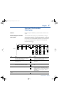
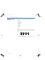

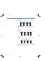
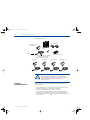
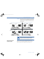


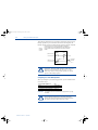

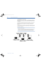
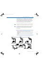
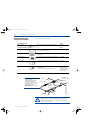
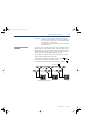
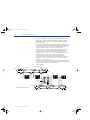
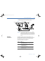


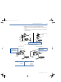
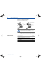


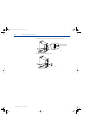

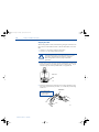

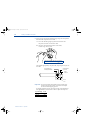
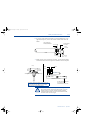
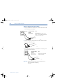


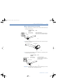
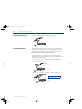
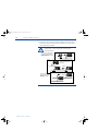
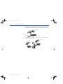
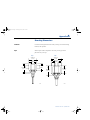


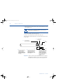

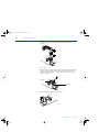


![[SPT-3000] e](http://vs1.manualzilla.com/store/data/005667089_1-a5f3766b3193f6552f250995926a69c5-150x150.png)