1
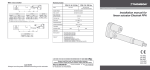
www.thomsonlinear.com
Installation manual for
actuator controls type DCG
Basic mounting
6,8
13
5
2,8
103
45
252
37
264
6,3
55
50
30
24
Control designation
and technical data
170
L = 1200
Note! the hand control
is ordered separately and
is not supplied with the
control box as standard.
Min. 0 °C
Max. + 30 °C
Indoor use only!
Connection of hand control DCG14-1H
Extend / forward / up
Retract / backwards / down
HS
Connection of direction inputs and motor outputs
Output M1
Input HS
X
HS
M1
X
Y
+5V
Y
4
8
Input HS
Pin
M
+5V
8 7 6
DCG14-1H
5
1 2 3 4
Output M1
X
Y
4
8
OFF
OFF
0V
0V
ON
OFF
+24V
0V
OFF
ON
0V
+24V
ON
ON
0V
0V
Connection of single actuator to motor outputs
Output M1
8
4
M1
A
Pin configuration motor output M1
8
7
6
5
1
2
3
4
B
M
Front view
Control designation
DCG24-1 • -0150
DCG24-1 • -0150
DCG24-1 • -0152
DCG24-1 • -0154
DCG24-1 • -0160
DCG24-1 • -0170
DCG24-1 • -0170
DCG24-1 • -0180
Actuator type
LA1
E050, Q050
Whispertrak 2 kN version
Whispertrak 4 kN version
LM80 for vertical operation*
LM80 for horizontal operation**
E150
TC16
Lead A
Lead B
yellow
white
black
red
use option Molex plug
use option Molex plug
use actuator plug
use actuator plug
red
black
use actuator plug
* LM80 designation = DT• • – • • • • • • • • • V • **LM80 designation = DT• • – • • • • • • • • • H •
Connection of parallel actuators to motor outputs
M1
M2
Actuator 1 Actuator 2
Motor outputs
Control designation
Actuator type
M1
M2
DCG24-2 • -0260
2 × LM80-I encoder* use actuator plugs
DCG24-2 • -0280
2 × TC16 encoder** use actuator plugs
* LM80-I designation= DT24– • • • • – • • • GCVE
**TC16 designation = TC16 –24T12M • • • • • • E
Reset procedure for parallel operating actuators
The following reset procedure is necessary at every power on or if the units
has become misaligned.
1. Press retract/down key until the actautor reach the innermost/lowest
possible pre-programmed end position and release the key.
2. Press and hold retract/down again. After about 5 seconds the units will
start to move slowly again until the units has reached their absolute end
position.
3. Release key down. The units is now aligned and ready for normal
operation.
Technical data
CONTROL DCG
Supply voltages*
230 ± 6 % Vac 50 Hz
115 ± 6 % Vac 60 Hz
Output voltage
Output current, max.
DCG24-1 • -0150
DCG24-1 • -0160
DCG24-1 • -0170
DCG24-1 • -0180
DCG24-2 • -0260
DCG24-2 • -0280
24 Vdc
4A
8 A up / 5,6 A down
8A
8A
2 × 8 A up / 2 × 5,6 A down**
2 × 8 A**
Standby power consumption, max.
0,3 W
Weight of control
0,4 kg
Power supply cable length
Operating temperature limits
3m
0 – 30 °C
Max. duty cycle @ 25 °C
10 %
Max. on time @ 25 °C
120 s
Operating humidity (non-condensing)
Protection class / IP class class
5 – 85 %
class 1 / IP20
HAND CONTROL DCG14-1H***
Weight
0,418 KG
Cable length
1,8 m
* See label on the control for information on the correct supply voltage for your control.
** Double outputs for parallel synchronious operation of two actuators.
*** Optional, ordered separately.
CAUTION!
Make sure to always turn the power off before working on the actuator or the wiring.
TOLLO LINEAR AB
Box 9053, SE-291 09 Kristianstad, Sweden
Tel. +46 (0)44-246700 Fax. +46 (0)44-244085
PRINTED IN SWEDEN
© 2012 DW110548gb-1239
Printed on recycled paper