1
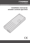
Wire cross section
Technical data
PPA 12, 24, 36 Vdc
U
2
mm
12 VDC
24 VDC
36 VDC
Motor
400
12 VDC
L=3m
1,5
2,5
4
mm 2
L=6m
2,5
4
6
DC-motor
AC-motor with
auto reset thermal switch
2 mm2
L
Current
[A]
0 – 15
16 – 20
21 – 28
PPA 110, 230 Vac
24 VDC
L = 10 m
4
6
10
Current
[A]
0 – 10
11 – 15
Supply voltage
see label on actuator
Max. current
see label on actuator
Installation manual for
linear actuator Electrak PPA
36 VDC
mm 2
L=6m
L = 10 m
1,5
1,5
2,5
2,5
Current
[A]
0 – 12
mm 2
L = 10 m
1,5
Max. static load
@ fully retracted
13 350 N
End play max.
www.ThomsonLinear.com
1 mm
Duty cycle
30 % @ 20° C
The tables are based on ambient temperature = 30 °C or less.
Restraining torque
5 Nm
Ambient temperature
U
Lubrication
mm2
110 VAC
230 VAC
0,75 mm
L
110 / 230 VAC
Current [A]
L [m]
0–2
0 – 20
– 25 to + 65° C
2
500
mm2
1,5
for life
Protection class
IP44
Slip clutch
IP44
yes
Brake options*
• No brake option (code N–)
• Anti coast brake (code SB)
• Electrical brake (code EB)
Options**
• No option (code XX)
• Limit switches (code LS)
• Potentiometer feedback (code PO)
• Hall effect sensor feedback (code HS)
• Hall effect sensor feedback + limit swiches (code HL)
* See position 15 and 16 on the actuator's type designation label, e.g. PPA22–58B65–06SBXXX
** See position 17 and 18 on the actuator's type designation label, e.g. PPA22–58B65–06SBLSX
Always install fuse and / or thermal breaker between
motor and power supply to protect actuator, wiring and other items.
CAUTION!
Always turn the power off before working on the actuator.
TOLLO LINEAR AB
PRINTED IN SWEDEN
Box 9053, SE-291 09 Kristianstad, Sweden
Tel. +46 (0)44-246700 Fax. +46 (0)44-244085
©
2009 DW110503gb-0946
Printed on recycled paper
12 VDC
24 VDC
36 VDC
110 VAC
230 VAC
Basic mounting rules
F
F
kg
Connection of potentiometer
Connection of actuator motor
black
+
kg
12 VDC
24 VDC
36 VDC
STOP
min. stroke = 0 W
red
–
OK
Without electrical brake
OK
6
5
yellow/green
red
PE
L
4
gray
STOP
brown
To get access to the conenction terminals the
rear cover of the actuator must be removed.
10kW
black (blue)*
white (yellow)*
N
max. stroke = 10 kW
Resistance increase between white and
brown when extending actuator.
white
C**
110 VAC
230 VAC
Only install the actuator in these points!
(option**)
Connection of hall effect sensor
(option**)
* Old(new motor).
**Capacitor comes installed in the actuator from factory: 110 VAC = 25 mF, 230 VAC = 6 mF
!
Only use solid pins
With electrical brake
14
ø 13,1
yellow/green
red
ø 25
PE
L
ø 12,7 ±1,3
10
1,18 pulse/mm
C*
STOP
110 VAC
blue
Input voltage
4,5 - 12 Vdc
Output
brake
black
Temperature limits
Protection degree
0 Vdc
N
6
5
4
green
+
black
O
red
-
To get access to the conenction terminals the
rear cover of the actuator must be removed.
yellow
*Capacitor comes installed in the actuator from factory: 110 VAC = 25 mF
IP44
Min. – 25 °C
Connection of limit switches
Pulses will be generated on the output when
the actuator is moving. The output voltage
will change from the input voltage to just
above 0 Vdc as the pulses are generated.
Connection of limit switches + hall effect sensor (option**)
(option**)
Max. + 65 °C
Restraining torque
min. stroke =
stop retract
min. stroke =
stop retract
max. stroke =
stop extend
Torque needed to prevent the extension tube from rotating.
1,18 pulse/mm
Stop extend
5 Nm
max. stroke =
stop extend
Stop retract
6
5
4
blue
Stop extend
Limit switches
white
green
The limit switches are set from factory to actuate
the limit switches at the fully extended and fully
retracted positions. Do NOT rotate the extension
tube as that will re-set the setting of the
limit switch positions. To get access to
the conenction terminals the rear cover of the actuator must be removed.
Stop retract
Cam stop extend
Cam stop retract
Cam locking
screws
Input voltage
4,5 - 12 Vdc
Output
0 Vdc
6
5
4
3
2
1
blue
white
green
green
+
black
O
red
-
To get access to the conenction terminals the
rear cover of the actuator must be removed.
Pulses will be generated on the output when
the actuator is moving. The output voltage
will change from the input voltage to just
above 0 Vdc as the pulses are generated.
The limit switches are set from factory to
actuate the limit switches at the fully extended
and fully retracted positions. Do NOT rotate
the extension tube as that will re-set the
setting of the limit switch positions.