1
Installation Manual QT250 and QT800_rev C
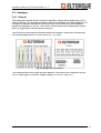
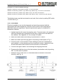
Fig. 7. Analog interface connected to analogue controller
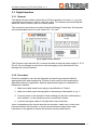
3.4.2 Procedure
Electrical installation can only be designed and made by personnel with the
appropriate skills and competence. Ensure all such work is done according to
applicable laws and regulations. Special requirements apply for installation in
hazardous locations.
1. Make sure cable used is according to specification in Table 1.
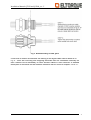
2. Make sure cable input through gland is according to description in Fig. 3.
3. Connect power to the actuator. Power cabling can be done individually to
each actuator, or the actuators can be connected in series.
4. Connect the signal cable to the input and output terminals.
When re-assembling the control box with the actuator, make sure no wires are
jammed between the surfaces. It is also recommended to apply some seal
lubrication on the gasket to ensure the actuator remains water proof.
3.5 Field bus solution
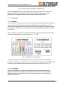
The actuators with a field bus interface, Modbus or CanOpen can very simplified be
described as one signal cable from the control unit and to the first actuator, and then
continue to the next actuator and so on until you have a “string” with actuators. Each
actuator in the string has a unique address.
11