1
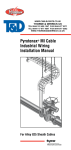
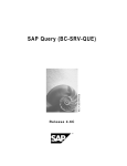
Industrial MI Wiring
Cable Termination
INSTALLATION MANUAL FOR SYSTEM 2000 AND
SYSTEM 2200 WIRING SYSTEMS
THERMAL MANAGEMENT SOLUTIONS
WWW.THERMAL.PENTAIR.COM
Important Safeguards and Warnings
WARNING: FIRE AND SHOCK HAZARD.
Pyrotenax Industrial Wiring Cables must be installed
correctly to ensure proper function and to minimize
the risk of personal injury or fire. Read these important warnings and carefully follow the installation
instructions.
•When MI cable is stripped and terminated, cut metal
edges can cause cuts and loose powder can cause eye
irritation. To prevent injury, gloves and safety glasses
must be worn when carrying out these operations.
•To prevent burns when drying or brazing the cable,
allow it to cool until warm to the touch before completing the remaining termination instructions.
•Avoid skin or eye irritation from contact with the
epoxy sealing compound. If accidental contact occurs,
wash skin with soap and water, or flush eyes with
water for 15 minutes. Consult MSDS* for further precautions and treatments.
•The insulation resistance (IR) test can cause sparks.
To prevent fires in hazardous locations, be sure there
are no flammable vapors in the area before performing this test.
*MSDS sheets for the epoxy sealing compoind, mastic
sealing compound, silver solder and the silver brazing flux are available on our website:
www.thermal.pentair.com
ii
EN-PyrotenaxIndustrialWiringCable-IM-H58121 03/13
Table of Contents
1
2
3
4
General Information
1
1.1 Use of the Manual
1
1.2 Safety Guidelines
2
1.3 Moisture Absorption
3
1.4Grounding/Earthing
3
1.5 Field Testing
3
1.6Approvals
4
Installation5
2.1 Strip-back Tail Termination Procedure
5
2.2 Crimp-on Tail Termination Procedure
23
2.3 Brazed-on Tail Termination Procedure
29
Troubleshooting Guide
52
Appendixes54
EN-PyrotenaxIndustrialWiringCable-IM-H58121 03/13
iii
iv
EN-PyrotenaxIndustrialWiringCable-IM-H58121 03/13
1
1.1
General Information
Use of the Manual
This installation manual covers the termination
procedure for Pyrotenax Alloy 825 sheath mineral
insulated (MI) wiring cables. The instructions show
how to make MI cable terminations using stripback tails, crimp-on tails or brazed-on tails with
either the mastic sealing compound or epoxy sealing compound. Use the chart following to identify
which termination kit has been supplied and read the
appropriate instruction steps completely before performing the termination procedure.
Strip-back Tail Termination Procedure
• Mastic sealing compound - page 9, Steps 1 to
19
• Epoxy sealing compound - page 9, Steps 1 to
13, 14a to 19a
Crimp-on Tail Termination Procedure
• Mastic sealing compound - page 27, Steps 1 to 6
• Epoxy sealing compound - page 27, Steps 1 to 6
Brazed-on Tail Termination Procedure (uses epoxy
sealing compound)
• Insulated stranded wire tails - page 33, Steps 1
to 19
• Bare stranded wire tails and insulating sleeving page 33, Steps 1 to 7, 8a to 19a
For information on installing and supporting
Pyrotenax Alloy 825 sheath MI wiring cables,
refer to the Pyrotenax MI Cable Industrial Wiring
Installation Manual (H57987). For fire-rated systems,
the termination must be protected from the fire as
described in the Pyrotenax MI Cable Industrial Wiring
Installation Manual (H57987).
For technical support or for further information on
terminating MI wiring cables, please contact your
Pentair Thermal Management representative or
Pentair Thermal Management directly.
EN-PyrotenaxIndustrialWiringCable-IM-H58121 03/13
1
1
General Information
For additional information, contact:
Pentair Thermal Management
7433 Harwin Drive
Houston, TX 77036
USA
Tel:+1.800.545.6258
Tel:+1.650.216.1526
Fax:+1.800.527.5703
Fax:+1.650.474.7711
[email protected]
www.thermal.pentair.com
1.2
Safety Guidelines
The instructions contained in this booklet are important. Follow them carefully to avoid injuries and to
ensure that the MI cable is properly terminated.
When MI cable is stripped and terminated, cut metal
edges can cause abrasions to the hands and loose
powder may cause irritation if it enters the eyes. For
these reasons gloves and safety glasses must be
used when carrying out these operations.
• Important instructions are marked
• Safety warnings are marked
• Safety cautions are marked
2
Important
WARNING
CAUTION
EN-PyrotenaxIndustrialWiringCable-IM-H58121 03/13
1
1.3
General Information
Moisture Absorption
Because the magnesium oxide insulation of MI cable
is hygroscopic, it will absorb moisture when exposed
to air for any length of time, resulting in decreased
insulation resistance (IR). This can be corrected by
one of the following methods:
1.4
1.
When the cable sheath is stripped, the moisture affected magnesium oxide insulation will
normally be removed during the termination
procedure. To prevent further absorption of
moisture, the termination should be completed
immediately following the IR test.
2.
If excess cable is available, 6 to 12 in (150 to
300 mm) of cable may be removed from the end
before proceeding with the termination.
3.
Follow the drying out procedure in Appendix D.
Grounding/Earthing
If one conductor is to be used as a grounding conductor, ensure that it is identified with an appropriately colored marker or tape. The sleeving supplied
with the termination kit used to identify the grounding conductor may not be a standard color (such as
green or green/yellow).
1.5
Field Testing
The IR of MI cables should be checked with a 500
Vdc megohmmeter. While an IR value of infinity is
desirable, minimum acceptable IR values, and the
test procedure, are shown in Appendix C. Where low
IR readings are obtained the termination must be
remade.
EN-PyrotenaxIndustrialWiringCable-IM-H58121 03/13
3
1
1.6
General Information
Approvals
Termination kits are supplied with either a mastic sealing compound or epoxy sealing compound
and are approved for use in the locations shown
following.
U.S. and Canadian Approvals
Kits using mastic sealing compound
Ordinary Locations
Hazardous Locations
Class I, Div. 1 and 2, Groups A, B, C, D
Class II, Div. 1 and 2, Groups E, F, G
Class III, Div. 1 and 2
Kits using epoxy sealing compound
Ordinary Locations
Hazardous Locations
Class I, Div. 1 and 2, Groups A, B, C, D
Class II, Div. 1 and 2, Groups E, F, G
Class III, Div. 1 and 2
ATEX Approved Components
MI Cable Seal Assembly
II 2G EEx e ll
Baseefa02ATEX0194U
Cable Glands
II 2GD EEx d llC
Baseefa03ATEX0347X
1180
4
EN-PyrotenaxIndustrialWiringCable-IM-H58121 03/13
2
Installation
2.1
Strip-back Tail Termination Procedure
In this procedure, the cable end is sealed using the
mastic sealing compound or epoxy sealing compound supplied with the termination kit. The tails
are formed by removing an appropriate length of the
cable sheath and covering the exposed solid conductors with insulating sleeving.
Figure 1 shows the components of each termination
kit. Visually check the parts supplied with the termination kit to identify which sealing compound has
been supplied and follow the appropriate steps to
terminate the cable.
EN-PyrotenaxIndustrialWiringCable-IM-H58121 03/13
5
2
Installation
Figure 1a: Kit parts for mastic sealing compound
Spacer disk and
insulating
sleeving
assembly
Set-screw
pot
Gland
connector
Mastic sealing
compound
Figure 1b: Kit parts for epoxy sealing compound
Spacer disk and
insulating
sleeving
assembly
Gland
connector
Set-screw
pot
Epoxy sealing
compound
Figure 1: Components supplied in strip-back tail
termination kits
6
EN-PyrotenaxIndustrialWiringCable-IM-H58121 03/13
2
Installation
The completed termination using the mastic sealing
compound is shown in Figure 2. Store the package
containing the mastic sealing compound at room
temperature prior to use.
Cable must project
1/8 in (3 mm) into pot
Set-screws
Spacer disk
MI cable
Gland connector
Anchoring bead
Thread
Set-screw pot
Insulating
sleeving
Mastic sealing
compound
Figure 2: Completed mastic sealing compound
termination (cut-away pot shown)
The completed termination using the epoxy sealing
compound is shown in Figure 3. The epoxy sealing
compound must be stored at temperatures between
65°F to 77°F (18°C to 25°C), and when used, must
be maintained at a temperature of 65°F (18°C) minimum for 16 hours to fully cure. Note that the spacer
disk is discarded once the epoxy has cured.
Cable must project
1/8 in (3 mm) into pot
Set-screws
Anchoring beads
Spacer disk
(discard after
epoxy cures)
MI cable
Gland connector
Thread
Set-screw pot
Epoxy sealing
compound
Insulating
sleeving
Figure 3: Completed epoxy sealing compound
termination (cut-away pot shown)
EN-PyrotenaxIndustrialWiringCable-IM-H58121 03/13
7
2
Installation
Tools and Materials Required:
• Pyrotenax T-bar stripping tool
• Pyrotenax hand vise
• Pyrotenax crimping and compression tool (if terminating cable using mastic sealing compound)
• Diagonal (side) cutters
• Measuring tape or ruler
• Hacksaw
• Flat file
• Tubing cutter
• Adjustable pliers/vise grips
• Oxy-acetylene or mapp gas torch (to dry out cable)
• Permanent marker
• 500 Vdc megohmmeter
• Electrical tape (if terminating cable using epoxy
seal)
• Scribe or pick
• Medium grit emery paper
• Loctite 271 or equivalent permanent thread lock
compound
• Allen wrench set (1/16”, 3/32” and 1/8”)
• Clean dry cloth
• Safety glasses
• Gloves
8
EN-PyrotenaxIndustrialWiringCable-IM-H58121 03/13
2
Installation
CAUTION: Wear safety glasses and gloves during the termination procedure.
1.
With a hacksaw, cut the end of the MI cable
square and file the end smooth.
Ensure that the end of the MI cable is straight
for approximately the tail length required plus 6
in (150 mm). Place a mark on the sheath for the
tail length required, 12 in (300 mm) is standard.
6i
n(
15
0m
m)
Ta
il
len
gth
req
uir
ed
Mark
sheath
Cut and file
end smooth
Figure 4: Cut MI cable and mark sheath
2.
Place the gland connector and pot on to cable
as shown.
Gland connector
Pot
Figure 5: Place gland and pot on to cable
3.
Using the tubing cutter, score cable sheath
at the mark (see Appendix A for detailed
instructions).
EN-PyrotenaxIndustrialWiringCable-IM-H58121 03/13
9
2
Installation
Important: Do not cut completely through the
cable sheath as this will cause the sheath to curve in
towards the conductors.
Mark on
sheath
Figure 6: Score cable sheath with tubing cutter
4.
Grip cable firmly with Pyrotenax hand vise or
hold cable in a bench vise.
Important: Do not remove gland connector and
pot from cable.
Use diagonal side cutters to strip the cable
sheath, ensuring that the sheath is flared
slightly outwards (see Appendix A for detailed
instructions).
Score
Figure 7: Strip cable sheath with side-cutters
Alternatively, use the T-bar stripping tool to strip
the cable sheath ensuring that the cable sheath
is flared slightly outwards (see Appendix A for
detailed instructions).
10
EN-PyrotenaxIndustrialWiringCable-IM-H58121 03/13
2
Installation
Score
T-bar
tool
Figure 8: Strip cable sheath with T-bar tool
5.
Straighten the conductors, if required, and
ensure that they are evenly spaced.
Wipe around and in between all conductors and
end of sheath to remove loose powder.
Wipe around and in
between conductors
Figure 9: Clean conductors
6.
Using emery paper, lightly sand around and
in between all conductors for a length of 1 in
(25 mm) from the end of cable and the last 1 in
(25 mm) of conductors.
Avoid contaminating the magnesium oxide powder in the exposed cable end with the metal
filings; if contaminated, remove with a pick.
EN-PyrotenaxIndustrialWiringCable-IM-H58121 03/13
11
2
Installation
Emery paper
1 in
(25 mm)
Figure 10: Lightly sand conductors
7.
Place a mark at a length “E” (refer to table
below) from end of sheath.
Table 1
Pot Size
Length "E" to mark
1/2 in (13 mm)
5/16 in (8 mm)
3/4 in (19 mm)
7/16 in (11mm)
1 in (25 mm)
9/16 in (14 mm)
1-1/4 in (32 mm)
5/8 in (16 mm)
E
Mark
sheath
Figure 11: Mark sheath at length E
8.
12
Align back of the pot (previously installed) with
mark. Cable end will project approximately 1/8
in (3 mm) into the pot. Tighten set-screws to
hold pot in place.
EN-PyrotenaxIndustrialWiringCable-IM-H58121 03/13
2
Installation
Important: Cable end must project 1/8 in (3 mm)
into pot in order to make an effective seal.
Set-screw
Pot
Mark
Cable end must project
1/8 in (3 mm) into pot
Figure 12: Align pot with mark and tighten set-screws
9.
Optional: For added mechanical strength, the
pot may be brazed to the cable sheath as shown
in Appendix E. If brazing the pot to the cable
sheath, complete the steps in Appendix E first,
then proceed to Step 11, otherwise continue
with Step 10.
10. Remove moisture from cable by heating the last
6 in (150 mm) of cable with the mapp gas or
oxyacetylene torch. Begin 6 in (150 mm) back
from end and stroke flame towards end (see
Appendix D for detailed procedure).
CAUTION: Cable will be hot. Allow cable to cool
until just warm to the touch, then continue with the
steps following to seal the cable end.
Hea
t las
t 6”
(150
mm
) of
cab
le s
hea
th
Figure 13: Heat cable to remove moisture
EN-PyrotenaxIndustrialWiringCable-IM-H58121 03/13
13
2
Installation
11. Slide spacer disk and insulating sleeving
sub-assembly over conductors, anchoring bead
end first. If one end of the cable has been terminated, test the end-to-end continuity with a
continuity tester to ensure that each conductor has the same color sleeving at both ends.
Colored sleeving assemblies will be marked
with a red tag for one end and a green tag for
the other. A cable should not be terminated with
the same colored tag at both ends.
Pot
Spacer disk
Insulating
sleeving
Anchoring bead
Figure 14: Place insulating sleeving sub-assembly
over conductors
12. Using a 500 Vdc megohmmeter, check the insulation resistance (IR) of the cable to ensure it is
free of grounds and shorts:
–– Between conductor(s) and sheath and
–– Between conductor pairs
See Appendix C for detailed test procedure and
IR test criteria.
Once IR readings are satisfactory, immediately
apply the appropriate sealing compound as
described in the steps following. A delay will
cause the IR to drop and the cable must be
retested prior to sealing the end.
Important: Opposite end of cable must also be dry
and free of grounds and shorts to obtain an acceptable
IR reading. Low IR readings should be expected if the
opposite end has already been terminated with epoxy
sealing compound which has not fully cured (IR will
increase once the epoxy has cured).
14
EN-PyrotenaxIndustrialWiringCable-IM-H58121 03/13
2
Installation
Important: If neither cable end has yet been
terminated and IR readings are low, dry out both
ends following the procedure in Appendix D or cut off
shorted end and re-test. Apply a temporary moisture
resistant seal, such as hot melt glue or adhesive lined
heat-shrink tubing, to opposite cable end to prevent
moisture absorption.
5
10000
15 0
20000
2500
0
Figure 15: Check insulation resistance
13. For kits supplied with mastic sealing compound,
immediately complete Steps 14 through 19.
For kits supplied with epoxy sealing compound,
immediately complete Steps 14a through 19a.
14. Withdraw spacer disk and sleeving sub-assembly slightly to allow sealing compound to be
packed in.
Ensure conductors are spaced an equal distance apart from each other and the inside of
the pot.
The pot should still be warm following Step 10,
if not, heat the cable and then the pot with the
torch until just warm to the touch before filling
with mastic sealing compound.
Do not allow compound to become contaminated with any foreign matter once package is
opened. Press mastic sealing compound into
EN-PyrotenaxIndustrialWiringCable-IM-H58121 03/13
15
2
Installation
pot with thumb behind the wrapper to ensure
cleanliness. Slightly overfill pot with sealing
compound, pressing from one side only to prevent air pockets from forming. Sealing compound will come out the opposite side of the pot
when full.
Important: Store mastic sealing compound at
room temperature until ready to use.
Figure 16: Pack in sealing compound
15. Using a screwdriver or other tool, push spacer
disk into open end of the pot, ensuring that
the anchoring beads on sleeving butt against
inside face of the spacer disk. Do not push on
the sleeving as it may be forced back through
the cap and butt against the end of the cable,
preventing the compound from making an effective seal.
16
EN-PyrotenaxIndustrialWiringCable-IM-H58121 03/13
2
Installation
Mastic sealing
compound
Spacer
disk
Anchoring
bead
Figure 17: Push spacer disk into the open end of the
pot
16. Place the set-screw pot into the body of the
crimping and compression tool (hand adjustable
type shown) making sure that the sleeving is
inserted through the hole in the crimping plate.
The spacer disk end of the pot must fit inside
the three cone-shaped points on the crimping
plate.
Important: Hold the tool firmly, with vise grips if
needed, to prevent the tool from turning the pot.
Apply even pressure on the spacer disk by tightening the tool until the spacer disk is snugly
seated inside the opening of the pot and the
cone-shaped points crimp the side of the pot.
This will retain the spacer disk in position. The
termination is now complete.
Important: It is normal for the mastic sealing
compound to squeeze out the side of the pot as pressure is applied with the crimping and compression
tool.
EN-PyrotenaxIndustrialWiringCable-IM-H58121 03/13
17
2
Installation
MI cable
Pot
Crimping plate
Vise
grips
Sleeving
Figure 18: Crimp spacer disk into pot
17. On completion of the termination, check the
IR again with the 500 Vdc megohmmeter (see
Appendix C).
Important: Under adverse weather conditions,
lower IR readings may be encountered.
5
1000
1500
20000
2500
0
Figure 19: Check insulation resistance
18. Apply a drop of Loctite 271 or equivalent permanent thread lock compound to the top of each
set-screw.
18
EN-PyrotenaxIndustrialWiringCable-IM-H58121 03/13
2
e
tit
c
Lo 271
Installation
Set-screws
Figure 20: Apply thread lock compound to set-screws
19. Complete the termination at the opposite end
following the same procedure, if not already
done.
Sealing Cable End Using Epoxy Sealing Compound (continued from Step 13).
14a.Withdraw the spacer disk and sleeving subassembly slightly to allow space to fill the pot
with epoxy.
Ensure conductors are spaced an equal distance apart from each other and the inside of
the pot.
Temporarily wrap 4 to 5 turns of electrical tape
around the cable sheath, tightly in contact with
the back of the pot. This prevents the epoxy
sealing compound from leaking out of the pot.
Prepare epoxy sealing compound in accordance
with Steps 1 and 2 of the instructions (see
Appendix B for details).
Important: Use epoxy within 10 minutes after
mixing.
The pot should still be warm following Step 10
(or procedure in Appendix E), if not, heat the
cable and then the pot with the torch until just
warm to the touch before filling with epoxy. Be
careful not to melt the electrical tape.
EN-PyrotenaxIndustrialWiringCable-IM-H58121 03/13
19
2
Installation
Important: To avoid forming bubbles in the epoxy,
do not apply heat to the cable or the pot while filling
the pot with epoxy or after it has been filled.
Insulating
sleeving
Spacer disk
Anchoring beads
Set-screw pot
4 to 5 turns of
electrical tape
tight to back of pot
MI cable
Figure 21: Prepare pot for epoxy
15a.Cut one corner of plastic package containing
epoxy to make an opening of 1/8 in (3 mm).
Maintaining cable end vertically, squeeze the
epoxy into the pot. Pour it down one side of the
pot until it is completely filled.
CAUTION: Avoid skin contact with epoxy
compound. If accidental contact occurs, wash skin
with mild soap and water.
20
EN-PyrotenaxIndustrialWiringCable-IM-H58121 03/13
2
Installation
Gloves
Epoxy
resin
Tape
Figure 22: Fill pot with epoxy
16a.Slide sleeving towards pot and adjust its position so that the bottom anchoring bead and half
the upper bead are immersed in the epoxy. For
multi-conductor cable, maintain proper spacing
of conductors with spacer disk and keep disk
about 1-1/4 in (30 mm) above the pot.
Important: Bend the conductors slightly so that
the sleeving does not slide down into the epoxy.
Allow 16 hours at 65°F (18°C) minimum for the
epoxy to cure before moving the termination
from the vertical position. At lower temperatures, curing will take longer.
Important: Discard spacer disk after the epoxy
cures.
EN-PyrotenaxIndustrialWiringCable-IM-H58121 03/13
21
2
Installation
Bend sleeving
just above the
spacer disk
Spacer disk
(discard after
epoxy cures)
1-1/4 in
(30 mm)
Epoxy resin
Tape
Figure 23: Allow epoxy to cure
e
tit
c
Lo 271
17a.Apply a drop of Loctite 271 or equivalent permanent thread lock compound to the top of each
set-screw.
Set-screws
Figure 24: Apply thread lock compound to set-screws
18a.Complete the termination at the opposite end
following the same procedure, if not already
done.
22
EN-PyrotenaxIndustrialWiringCable-IM-H58121 03/13
2
Installation
19a.After the epoxy compound at both ends has fully
cured (16 hours), check the IR again with the 500
Vdc megohmmeter (see Appendix C).
Important: Under adverse weather conditions,
lower IR readings may be encountered.
5
10000
1500
2000
2500
0
Figure 25: Check insulation resistance
2.2
Crimp-on Tail Termination Procedure
In this procedure the cable end is sealed using the
mastic sealing compound or epoxy sealing compound supplied with the termination kit. The tails
are formed by removing a short length of the cable
sheath and covering the exposed solid conductors
with insulating sleeving. Insulated stranded wire
tails of the required length, supplied separately or
by the customer, are then spliced to the solid conductors using the crimp connectors included in the
termination kit.
Figure 26 shows the components of each termination kit. Visually check the parts supplied with the
termination kit to identify which sealing compound
has been supplied and follow the appropriate steps
to terminate the cable.
EN-PyrotenaxIndustrialWiringCable-IM-H58121 03/13
23
2
Installation
Figure 26a: Kit parts for mastic sealing compound
Spacer disk and
insulating sleeving
assembly
Gland
connector
Set-screw
pot
Crimp
connectors
Heat shrink
tubing
Mastic sealing
compound
Figure 26b: Kit parts for epoxy sealing compound
Spacer disk and
insulating sleeving
assembly
Gland
connector
Set-screw
pot
Crimp
connectors
Heat shrink
tubing
Epoxy sealing
compound
Figure 26: Components supplied in crimp-on tail
termination kits
24
EN-PyrotenaxIndustrialWiringCable-IM-H58121 03/13
2
Installation
The completed termination using the mastic sealing
compound is shown in Figure 27. Store the package
containing the mastic sealing compound at room
temperature prior to use.
Anchoring bead
Cable must project
1/8 in (3 mm) into pot
Spacer disk
Insulating
sleeving
Set-screws
MI cable
Gland connector
Thread
Set-screw pot
Insulated
stranded
wire tails
Crimp (butt)
connectors
Mastic sealing Heat shrink
compound
Figure 27: Completed mastic sealing compound
termination (cut-away pot shown)
The completed termination using the epoxy sealing
compound is shown in Figure 28. The epoxy sealing
compound must be stored at temperatures between
65°F to 77°F (18°C to 25°C), and when used, must
be maintained at a temperature of 65°F (18°C) minimum for 16 hours to fully cure. Note that the spacer
disk is discarded once the epoxy has cured.
Cable must project
1/8 in (3 mm) into pot
Set-screws
Anchoring beads
Spacer disk (discard
after epoxy cures)
Insulating Insulated
sleeving
stranded
wire tails
MI cable
Gland connector
Thread
Set-screw pot
Crimp (butt)
connectors
Epoxy
Heat shrink
sealing
compound
Figure 28: Completed epoxy sealing compound
termination (cut-away pot shown)
EN-PyrotenaxIndustrialWiringCable-IM-H58121 03/13
25
2
Installation
Tools and Materials Required:
• Pyrotenax T-bar stripping tool
• Pyrotenax hand vise
• Pyrotenax crimping and compression tool (if terminating cable using mastic sealing compound)
• Diagonal (side) cutters
• Hacksaw
• Flat file
• Measuring tape or ruler
• Tubing cutter
• Adjustable pliers/vise grips
• Oxy-acetylene or mapp gas torch (to dry out cable)
• Permanent marker
• 500 Vdc megohmmeter
• Electrical tape (if terminating cable using epoxy
seal)
• Wire stripper
• Scribe or pick
• Medium grit emery paper
• Loctite 271 or equivalent permanent thread lock
compound
• Allen wrench set (1/16”, 3/32” and 1/8”)
• Crimping tool (approved for use with supplied
crimp connectors)
• Heat gun
• Clean dry cloth
• Safety glasses
• Gloves
• Insulated stranded wire of appropriate AWG (mm2)
size, length and temperature rating – supplied
separately or by customer
26
EN-PyrotenaxIndustrialWiringCable-IM-H58121 03/13
2
Installation
CAUTION: Wear safety glasses and gloves during the termination procedure.
1.
With hacksaw, cut the end of the MI cable
square and file the end smooth.
Ensure that the end of the MI cable to be terminated is straight for 10 in (250 mm). Place a
mark on the sheath 4 in (100 mm) from end of
the cable; this is the length of sheath to strip.
Important: If a longer length of solid conductor
tail is required, adjust the dimensions shown accordingly and strip the required length of cable sheath.
10
in
(25
0m
m)
4i
n(
10
0m
m)
Mark
sheath
Cut and file
end smooth
Figure 29: Cut MI cable and mark sheath
2.
Follow Steps 2 through 19 of the “Strip-back
Tail Termination Procedure” to terminate the
cable using the mastic sealing compound (page
7), then continue with Step 3 below.
Follow Steps 2 through 19a of the “Strip-back
Tail Termination Procedure” to terminate
the cable using the epoxy sealing compound
(page 7), then continue with Step 3 below.
3.
If the cable ends were terminated using the
epoxy sealing compound, proceed only after the
epoxy has fully cured and discard the spacer
disk.
Strip just enough insulating sleeving so that the
end of the solid conductor touches the center-
EN-PyrotenaxIndustrialWiringCable-IM-H58121 03/13
27
2
Installation
stop in the crimp connector (the sleeving supplied with the termination kit may be longer
than the solid conductor tails).
Strip the insulation from the insulated stranded
wire (not shown) just enough to touch the center stop in the crimp connector.
Ap
pro
x. 3
-1/
4i
n(
80
mm
)
Strip enough sleeving so that
conductor touches center-stop
in crimp connector
Figure 30: Strip insulating sleeving
4.
Insert the stripped conductors into the crimp
connector and crimp the connector using a
crimping tool which has been approved by a
certifying agency for use with the connector.
Crimp connector
Insulated stranded wire
Figure 31: Crimp the connectors
28
EN-PyrotenaxIndustrialWiringCable-IM-H58121 03/13
2
Installation
5.
Place supplied heat shrink tubing over the
crimp connector ensuring the heat shrink overlaps the insulating sleeving and the insulated
stranded wire tail equally and apply heat to
shrink the tubing in place over the connector.
Take care not to damage the heat shrink, insulating sleeving, or insulated stranded wire when
applying heat.
Insulating sleeving
Heat shrink tubing
over crimp connector
Insulated stranded wire
Figure 32: Apply heat to shrink tubing
6.
2.3
Complete the termination at the opposite end
following the same procedure, if not already
done.
Brazed-on Tail Termination Procedure
In this procedure, the cable end is sealed using the
epoxy sealing compound supplied with the termination kit. The termination kit may be supplied with
insulated stranded wire tails or with bare stranded
wire tails and insulating sleeving. For both terminations, the stranded wire tails are silver soldered
(brazed) to the solid MI conductor and the pot is silver soldered to the cable sheath. Follow the appropriate steps to complete the termination.
Figure 33 shows the components of each termination kit. Visually check the parts supplied with the
termination kit to identify which type of tails have
been supplied and follow the appropriate steps to
terminate the cable.
EN-PyrotenaxIndustrialWiringCable-IM-H58121 03/13
29
2
Installation
Important: As an alternative to the brazed-on pot,
termination kits may be supplied with set-screw pots
as shown in Section 2.1, Figure 1. These pots do not
have to be silver soldered to the cable sheath.
To install the set-screw pot when using insulated
stranded wire tails, replace Step 11, Step 12, and Step
13, with Step 8 and Step 10 of Section 2.1.
To install the set-screw pot when using bare stranded
wire tails and insulating sleeving, replace Steps 11a,
12a, and 13a, with Step 8 and Step 10 of Section 2.1.
30
EN-PyrotenaxIndustrialWiringCable-IM-H58121 03/13
2
Installation
Figure 33a: Brazed-on tails for insulated stranded wire
Insulated
stranded
wire tails
Gland
connector
Pot
Epoxy sealing
compound
Figure 33b: Brazed-on tails for bare stranded wire and
insulating sleeving
Spacer disk and
insulating sleeving
assembly
Gland
connector
Pot
Bare stranded
wire tails
Epoxy sealing
compound
Figure 33: Components supplied in brazed-on tail
termination kits
Figure 34 shows the completed termination using
insulated stranded wire tails. Figure 35 shows the
completed termination using bare stranded wire tails
and insulating sleeving. The epoxy sealing compound
must be stored at temperatures between 65°F to
77°F (18°C to 25°C), and when used, must be maintained at a temperature of 65°F (18°C) minimum for
16 hours to fully cure. Note that the spacer disk is
discarded once the epoxy has cured.
EN-PyrotenaxIndustrialWiringCable-IM-H58121 03/13
31
2
Installation
Cable must project
1/8 in (3 mm) into pot
Epoxy
sealing
compound
Insulated
stranded
wire tails
Thread
MI cable
Gland connector
Silver solder pot to
cable sheath
Silver soldered joint
Pot
Figure 34: Completed termination using insulated
stranded wire tails (cut-away pot shown)
Cable must project
1/8 in (3 mm) into pot
Epoxy sealing compound
Anchoring beads
Thread
Spacer disk
(discard after
epoxy cures)
MI cable
Gland connector
Silver solder pot to
cable sheath
Silver
soldered joint
Insulating
sleeving
Pot
Figure 35: Completed termination using bare stranded
wire tails and insulating sleeving (cut-away pot shown)
32
EN-PyrotenaxIndustrialWiringCable-IM-H58121 03/13
2
Installation
Tools and Materials Required:
• Pyrotenax hand vise
• Diagonal (side) cutters
• Hacksaw
• Flat file
• Tubing cutter
• Workbench
• Measuring tape or ruler
• Permanent marker
• Micrometer
• 500 Vdc megohmmeter
• Wire stripper
• Scribe or pick
• Medium grit emery paper
• Clean dry cloth
• Safety glasses
• Gloves
• Oxy-acetylene torch with Victor No. 0 welding tip
(or equivalent)
• Handy & Harman 1/16 in (1.6 mm) or 1/32 in
(0.8 mm) diameter “Braze 560” silver solder (or
equivalent)
• Prostar silver brazing flux (or equivalent)
• Drill press and appropriately sized drill bits
(required if the pot was not pre-drilled at the
factory)
CAUTION: Wear safety glasses and gloves during the termination procedure.
1.
Prepare bare or insulated stranded wire tails for
use later. If insulated stranded wire is supplied
in the termination kit, strip 3/16 to 1/4 in (5 to
6.4 mm) of insulation from ends.
Important: Two tails of the same color are
required; one for each end of each conductor in the
cable.
EN-PyrotenaxIndustrialWiringCable-IM-H58121 03/13
33
2
Installation
Apply flux to one end of a group of conductors. Align
group along edge of workbench and “tin” using oxyacetylene torch and silver solder ensuring that a
small “ball” of solder forms on the end of each conductor. If insulated stranded wire is supplied with the
kit, take care not to melt the insulation.
Silver
solder
Stranded
wire tails
Oxy-acetylene
torch
“Ball” of
silver solder
on end of
conductor
3/16 - 1/4 in
(5 - 6.4 mm)
Figure 36: Tin the ends of the conductors
2.
With hacksaw, cut the end of the MI cable
square and file end smooth. Make sure face of
conductors is completely clean of all foreign
material.
Use emery paper to polish all around surface
of cable sheath from end to about 2 in (50
mm) back from end (sheath must be clean for
brazing).
2i
n(
50
mm
)
Emery paper
Cut and file end smooth
(face of conductors must be clean)
Figure 37: Polish surface of cable sheath
34
EN-PyrotenaxIndustrialWiringCable-IM-H58121 03/13
2
Installation
3.
Ensure that the end of the MI cable to be terminated is straight for approximately 9 in (230
mm). Place a mark on the sheath 3/16 in (5
mm) from end of the cable; this is the length of
sheath to strip.
9i
n(
23
0m
m)
3/1
(5 6 in
mm
)
Mark
sheath
Figure 38: Cut MI cable and mark sheath
4.
Place the gland connector and the pot on to
cable as shown.
Important: If the pot does not fit over the MI cable,
measure the cable diameter using a micrometer
and drill the hole in the pot to a size that is 0.002 to
0.004 in (0.05 to 0.1 mm) larger than the cable diameter using a drill press and appropriately sized drill
bits.
Gland connector
Pot
Figure 39: Place gland and pot on to cable
EN-PyrotenaxIndustrialWiringCable-IM-H58121 03/13
35
2
Installation
5.
Using the tubing cutter, score cable sheath
at the mark (see Appendix A for detailed
instructions).
Important: Do not cut completely through the
cable sheath as this will cause the sheath to curve in
towards the conductors.
Mark on
sheath
Figure 40: Score cable sheath with tubing cutter
6.
Grip cable firmly with Pyrotenax hand vise or
hold cable in a bench vise if available.
Important: Do not remove gland assembly and pot
from cable.
Use diagonal side cutters to strip the cable
sheath, ensuring that the sheath is flared
slightly outwards (see Appendix A for detailed
instructions).
Score
Figure 41: Strip cable sheath with side-cutters
36
EN-PyrotenaxIndustrialWiringCable-IM-H58121 03/13
2
Installation
7.
If the termination kit is supplied with insulated
stranded wire tails, continue with Step 8.
If the termination kit is supplied with bare
stranded wire tails and insulating sleeving, continue with Step 8a.
8.
Lightly coat only the face of the solid
conductor(s) with flux. Do not allow the magnesium oxide at the end of the cable to become
contaminated with flux; if contaminated, you
must cut off 1/2 in (13 mm) of cable and start
over from Step 2.
If one end of the cable has been terminated,
test the end-to-end continuity with a continuity
tester to ensure that each conductor has the
same color stranded wire tails at both ends.
Next, braze the appropriate color insulated
stranded wire (prepared in Step 1), to the face
of each solid conductor by applying heat to the
solidconductor. This will draw the solder “ball”
from the stranded conductor to the solid conductor making a strong joint.
MI cable
Brazed joint
Insulated
stranded wire
Figure 42: Braze the conductors
9.
Using a thin strip of emery paper, lightly sand
around and in between all conductors to remove
magnesium oxide powder from solid conductors
and any excess flux from brazed joint.
Avoid contaminating the magnesium oxide powder in the exposed cable end with metal filings;
if contaminated, remove with a pick.
EN-PyrotenaxIndustrialWiringCable-IM-H58121 03/13
37
2
Installation
MI cable
Emery paper
Figure 43: Remove flux and lightly sand conductors
10. Place a mark at a length “E” (refer to table
below) from end of sheath.
Table 2
Pot Size
Length "E" to mark
1/2 in (13 mm)
5/16 in (8 mm)
3/4 in (19 mm)
7/16 in (11 mm)
1 in (25 mm)
9/16 in (14 mm)
1-1/4 in (32 mm)
5/8 in (16 mm)
E
Mark
sheath
Figure 44: Mark sheath at length E
11. Align back of the pot (previously installed) with
mark. Cable end will project approximately 1/8
in (3 mm) into the pot.
Important: Cable end must project 1/8 in (3 mm)
into the pot in order to make an effective seal.
38
EN-PyrotenaxIndustrialWiringCable-IM-H58121 03/13
2
Installation
Pot
Mark
Cable end must project
1/8 in (3 mm) into pot
Figure 45: Align back of pot with mark
12. Apply flux to the cable sheath and back of the
pot where it meets the cable sheath. This prevents oxidation of the metals during the next
step.
Next, remove moisture from cable by heating
the last 6 in (150 mm) of cable with the oxyacetylene torch. Begin 6 in (150 mm) back from
end and stroke flame towards the end (see
Appendix D for detailed procedure).
He
at
las
t6
” (1
50
mm
)o
fc
ab
le
sh
ea
th
Apply flux around
sheath and back
of the pot
Figure 46: Heat cable to remove moisture
13. Braze pot to cable sheath while the cable is still
hot. Ensure silver solder flows all around the
pot and sheath by moving the flame around the
cable.
Important: To make a good quality solder joint,
the silver solder rod must be coated with flux at all
times. Dip in flux as many times as necessary until
brazing operation is complete.
EN-PyrotenaxIndustrialWiringCable-IM-H58121 03/13
39
2
Installation
Important: Take care when heating the pot since
excess heat will cause the solder at the conductor
joints to melt.
CAUTION: Cable will be hot. Allow cable to cool
until just warm to the touch, then continue with the
steps following to seal the cable end.
Oxy-acetylene torch
Silver solder
Silver solder pot
to cable sheath
Pot
Figure 47: Braze pot to cable sheath
14. Using a 500 Vdc megohmmeter, check the insulation resistance (IR) of the cable to ensure it is
free of grounds and shorts:
–– Between conductor(s) and sheath and
–– Between conductor pairs
See Appendix C for detailed test procedure and
IR test criteria.
Once IR readings are satisfactory, immediately
seal the cable end as described in the steps following. A delay will cause the IR to drop and the
cable must be retested prior to sealing the end.
Important: Opposite end of cable must also be dry
and free of grounds and shorts to obtain an acceptable
IR reading. Low IR readings should be expected if the
opposite end has already been terminated with epoxy
sealing compound which has not fully cured (IR will
increase once the epoxy has cured).
40
EN-PyrotenaxIndustrialWiringCable-IM-H58121 03/13
2
Installation
Important: If neither cable end has yet been
terminated and IR readings are low, dry out both
ends following the procedure in Appendix D or cut off
shorted end and re-test. Apply a temporary moisture
resistant seal, such as hot melt glue or adhesive lined
heat-shrink tubing, to opposite cable end to prevent
moisture absorption.
5
10000
1500
20 0
25000
0
Figure 48: Check insulation resistance
15. Ensure conductors are spaced an equal distance apart from each other and the inside of
the pot.
Prepare epoxy sealing compound in accordance
with Steps 1 and 2 of the instructions (see
Appendix B for details).
Important: Use epoxy within 10 minutes after
mixing.
The pot should still be warm following Step 13,
if not, heat the cable and then the pot with the
torch until just warm to the touch before filling
with epoxy.
Important: To avoid forming bubbles in the epoxy,
do not apply heat to the cable and the pot during or
after the pot has been filled with epoxy.
EN-PyrotenaxIndustrialWiringCable-IM-H58121 03/13
41
2
Installation
Insulated stranded
wire tails
Pot
MI cable
Figure 49: Prepare pot for epoxy
16. Cut one corner of plastic package containing
epoxy to make an opening of 1/8 in (3 mm).
Maintaining cable end vertically, squeeze the
epoxy into the pot. Pour it down one side of the
pot until it is completely filled.
CAUTION: Avoid skin contact with epoxy
compound. If accidental contact occurs, wash skin
with mild soap and water.
Gloves
Epoxy
resin
MI cable
Figure 50: Fill pot with epoxy
42
EN-PyrotenaxIndustrialWiringCable-IM-H58121 03/13
2
Installation
17. Allow 16 hours at 65°F (18°C) minimum for the
epoxy to cure before moving the termination
from the vertical position. At lower temperatures, curing will take longer.
Tails
Epoxy
resin
Figure 51: Allow epoxy to cure
18. Complete the termination at the opposite end
following the same procedure, if not already
done.
19. After the epoxy compound at both ends has fully
cured (16 hours), check the IR again with the
500 Vdc megohmmeter (see Appendix C).
Important: Under adverse weather conditions,
lower IR readings may be encountered.
EN-PyrotenaxIndustrialWiringCable-IM-H58121 03/13
43
2
Installation
5
10000
15 0
20000
2500
0
Figure 52: Check insulation resistance
Bare Stranded Wire Tails and Insulating Sleeving
Termination (continued from Step 7)
8a. Lightly coat only the face of the solid
conductor(s) with flux. Do not allow the magnesium oxide at the end of the cable to become
contaminated with flux; if contaminated, you
must cut off 1/2 in (13 mm) of cable and start
over from Step 2.
Next, braze the bare stranded wire (prepared in
Step 1), to the face of each solid conductor by
applying heat to the solid conductor. This will
draw the solder “ball” from the stranded conductor to the solid conductor making a strong
joint.
MI cable
Brazed joint
Bare stranded wire
Figure 53: Braze the conductors
44
EN-PyrotenaxIndustrialWiringCable-IM-H58121 03/13
2
Installation
9a. Using a thin strip of emery paper, lightly sand
around and in between all conductors to remove
magnesium oxide powder from solid conductors
and any excess flux from brazed joint.
Avoid contaminating the magnesium oxide powder in the exposed cable end with metal filings;
if contaminated, remove with a pick.
MI cable
Emery paper
Figure 54: Remove flux and lightly sand conductors
10a.Place a mark at a length “E” (refer to table
below) from end of sheath.
Table 3
Pot Size
Length "E" to mark
1/2 in (13 mm)
5/16 in (8 mm)
3/4 in (19 mm)
7/16 in (11 mm)
1 in (25 mm)
9/16 in (14 mm)
1-1/4 in (32 mm)
5/8 in (16 mm)
E
Mark
sheath
Figure 55: Mark sheath at length E
EN-PyrotenaxIndustrialWiringCable-IM-H58121 03/13
45
2
Installation
11a.Align back of the pot (previously installed) with
mark. Cable end will project approximately 1/8 in
(3 mm) into the pot.
Important: Cable end must project 1/8 in (3 mm)
into the pot in order to make an effective seal.
Pot
Mark
Cable end must project
1/8 in (3 mm) into pot
Figure 56: Align back of pot with mark
12a.Apply flux to the cable sheath and back of the
pot where it meets the cable sheath. This prevents oxidation of the metals during the next
step.
Next, remove moisture from cable by heating
the last 6 in (150 mm) of cable with the oxyacetylene torch. Begin 6 in (150 mm) back from
end and stroke flame towards end (see Appendix
D for detailed procedure).
He
at
las
t6
” (1
50
mm
)o
fc
ab
le
sh
ea
th
Apply flux around
sheath and back
of the pot
Figure 57: Heat cable to remove moisture
46
EN-PyrotenaxIndustrialWiringCable-IM-H58121 03/13
2
Installation
13a.Braze pot to cable sheath while the cable is still
hot. Ensure silver solder flows all around the
pot and sheath by moving the flame around the
cable.
Important: To make a good quality solder joint,
the silver solder rod must be coated with flux at all
times. Dip in flux as many times as necessary until
brazing operation is complete.
Important: Take care when heating the pot since
excess heat will cause the solder at the conductor
joints to melt.
CAUTION: Cable will be hot. Allow cable to cool
until just warm to the touch, then continue with the
steps following to seal the cable end.
Oxy-acetylene torch
Silver solder
Silver solder pot
to cable sheath
Pot
Figure 58: Braze pot to cable sheath
14a.Using a 500 Vdc megohmmeter, check the
insulation resistance (IR) of the cable to ensure it
is free of grounds and shorts:
–– Between conductor(s) and sheath and
–– Between conductor pairs
See Appendix C for detailed test procedure and
IR test criteria.
Once IR readings are satisfactory, immediately
seal the cable end as described in the steps folEN-PyrotenaxIndustrialWiringCable-IM-H58121 03/13
47
2
Installation
lowing. A delay will cause the IR to drop and the
cable must be retested prior to sealing the end.
Important: Opposite end of cable must also be dry
and free of grounds and shorts to obtain an acceptable
IR reading. Low IR readings should be expected if the
opposite end has already been terminated with epoxy
sealing compound which has not fully cured (IR will
increase once the epoxy has cured).
Important: If neither cable end has yet been
terminated and IR readings are low, dry out both
ends following the procedure in Appendix D or cut off
shorted end and re-test. Apply a temporary moisture
resistant seal, such as hot melt glue or adhesive lined
heat-shrink tubing, to opposite cable end to prevent
moisture absorption.
5
1000
15000
2000
2500
0
Figure 59: Check insulation resistance
15a.Slide spacer disk and insulating sleeving
sub-assembly over the bare stranded wire,
anchoring bead end first. If one end of the cable
has been terminated, test the end-to-end continuity with a continuity tester to ensure that
each conductor has the same color sleeving at
both ends. Colored sleeving assemblies will be
marked with a red tag for one end and a green
tag for the other. One cable should not be terminated with the same colored tag at both ends.
48
EN-PyrotenaxIndustrialWiringCable-IM-H58121 03/13
2
Installation
Ensure conductors are spaced an equal distance apart from each other and the inside of
the pot.
Prepare epoxy sealing compound in accordance
with Steps 1 and 2 of the instructions (see
Appendix B for details).
Important: Use epoxy within 10 minutes after
mixing.
The pot should still be warm following Step 13a,
if not, heat the cable and then the pot with the
torch until just warm to the touch before filling
with epoxy.
Important: To avoid forming bubbles in the epoxy,
do not apply heat to the cable and the pot during or
after the pot has been filled with epoxy.
Insulating
sleeving
Spacer disk
Anchoring beads
Bare stranded
wire
Pot
MI cable
Figure 60: Prepare pot for epoxy
16a.Cut one corner of the plastic package containing
epoxy to make an opening of 1/8 in (3 mm).
Maintaining cable end vertically, squeeze the
epoxy into the pot. Pour it down one side of the
pot until it is completely filled.
EN-PyrotenaxIndustrialWiringCable-IM-H58121 03/13
49
2
Installation
CAUTION: Avoid skin contact with epoxy
compound. If accidental contact occurs, wash skin
with mild soap and water.
Spacer disk
Anchoring
beads
Gloves
Epoxy
resin
Pot
MI cable
Figure 61: Fill pot with epoxy
17a.Slide sleeving towards the pot and adjust its
position so that the bottom anchoring bead and
half the upper bead are immersed in the epoxy.
For multi-conductor cable, maintain proper
spacing of conductors with spacer disk and keep
disk about 1-1/4 in (30 mm) above the pot.
Important: Bend the conductors slightly so that
the sleeving does not slide down into the epoxy.
Allow 16 hours at 65°F (18°C) minimum for the
epoxy to cure before moving the termination
from the vertical position. At lower temperatures, curing will take longer.
Important: Discard spacer disk after the epoxy
cures.
50
EN-PyrotenaxIndustrialWiringCable-IM-H58121 03/13
2
Installation
Spacer disk
(discard after
epoxy cures)
1-1/4 in
(30 mm)
Epoxy resin
Figure 62: Allow epoxy to cure
18a.Complete the termination at the opposite end
following the same procedure, if not already
done.
19a.After the epoxy compound at both ends has fully
cured (16 hours), check the IR again with the 500
Vdc megohmmeter (see Appendix C).
Note: Under adverse weather conditions, lower IR
readings may be encountered.
5
1000
1500
20000
2500
0
Figure 63: Check insulation resistance
EN-PyrotenaxIndustrialWiringCable-IM-H58121 03/13
51
3
Troubleshooting Guide
Symptom
Insulation resistance is less than expected
Short circuits and direct earth faults
52
EN-PyrotenaxIndustrialWiringCable-IM-H58121 03/13
3
Troubleshooting Guide
Probable Causes
Corrective Action
1. Rain or high humidity.
(1) Dry tails and face of seal.
Inspect power connection box
for moisture or signs of tracking. Dry out connections and
retest.
2. Nicks or cuts in the cable
sheath, with moisture
present.
(2, 3, 4, 5) Visually inspect or
fault locate cable to find damaged section of cable. Repair or
replace cable or contact Pentair
Thermal Management technical
support for assistance.
3. Kinked or crushed cable.
4. Arcing created by damage
to the cable.
5. Welding splatter.
6. Presence of moisture in
termination or temporary
seal.
(6) Remove termination or
temporary seal. Dry out cable
following the procedure in
Appendix D. Replace termination or seal.
7. Damaged termination or
temporary seal.
(7) Replace termination or seal.
1. Physical damage to cable
is causing a direct short
from conductor to sheath.
(1) Check for visual indications
of damage around any area
where there may have been
maintenance work. Repair or
replace damaged cable and/or
terminations.
2. Misalignment of the
conductors within the
seal or incorrect and
untidy completion of the
sheath stripping procedure during termination.
(2) Remake termination.
3. Conductors shorted to
sheath when cut at factory (only for unterminated
cables).
(3) Remove short and reseal
end.
EN-PyrotenaxIndustrialWiringCable-IM-H58121 03/13
53
4
Appendixes
Appendix A: Stripping Pyrotenax® Alloy 825 Sheath MI
Cable
Using diagonal cutters
Measure, from cable end, length of cable sheath
to strip and mark sheath with marking pen. Use a
tube cutter to score around the sheath at the mark.
This will cause the sheath to peel away at the score
providing a smooth end when the sheath is stripped.
The correct depth of score is half the thickness of
the sheath.
Do not cut completely through the cable sheath as
this will cause the sheath to curve inwards toward
the conductor(s).
Mark on
Sheath
Tai
l
len
gth
req
uir
ed
Figure 64: Score cable sheath with tubing cutter
Grip the edge of the sheath between the jaws of
the side cutters and twist clockwise (twist counterclockwise if left-handed), then take a new grip and
rotate through a small angle.
Figure 65: Cut end of sheath and twist clockwise
54
EN-PyrotenaxIndustrialWiringCable-IM-H58121 03/13
4
Appendixes
Continue this motion in a series of short “rips,”
keeping the side cutters at about 45° to the line of
the cable, removing sheath spirally. Remove compacted powder insulation to expose conductors.
Score
Figure 66: Remove sheath and compacted powder
insulation
Continue removing the sheath to the score mark.
When about to break into the score, bring side cutters to right angle with cable. Finish off with point
of side cutters held parallel to the cable. The sheath
will peel away leaving a clean cut when the score
mark is reached.
Figure 67: Finish removing sheath at score mark
The cable sheath is correctly stripped, with the
sheath flared slightly outwards, as shown in (a)
In (b) the sheath is neither flared outwards nor beveled inwards, but is acceptable.
Ensure that the sheath is not curved or beveled
inward as shown in (c). This will occur if the score
EN-PyrotenaxIndustrialWiringCable-IM-H58121 03/13
55
4
Appendixes
made with the tube cutter is too deep. In this case,
remove a further 1/4 in (6 mm) of sheath.
Cable is now ready to be sealed.
(a)
Preferred
(b)
Acceptable
(c)
Unacceptable
Figure 68: Examples of stripped cable
Using the T-bar stripping tool
Measure, from cable end, length of cable sheath
to strip and mark sheath with marking pen. Use a
tube cutter to score around the sheath at the mark.
This will cause the sheath to peel away at the score
providing a smooth end when the sheath is stripped.
The correct depth of score is half the thickness of
the sheath.
Do not cut completely through the cable sheath as
this will cause the sheath to curve inwards toward
the conductor(s).
Mark on
Sheath
Tai
l
len
gth
req
uir
ed
Figure 69: Score cable sheath with tubing cutter
56
EN-PyrotenaxIndustrialWiringCable-IM-H58121 03/13
4
Appendixes
Cut the end of the sheath of the MI cable with side
cutters as shown and peel sheath to give approximately 5/8 in (15 mm) tag. Straighten the tag and
insert into slot in T-bar stripping tool.
Figure 70: Cut end of sheath to make tag
Hold T-bar tool at 45° angle, twist handle and revolve
tool around the cable carefully.
Continue twisting the tool around the cable maintaining a 45° angle to the line of the cable allowing
the metal turnings to spiral along the stripping tool.
Remove compacted powder insulation to expose
conductors.
When peeling a long length of cable, cut and remove
the metal turnings frequently.
Score
T-bar
tool
Figure 71: Strip cable sheath with T-bar tool
Continue removing the sheath to the score mark
using the T-bar stripping tool. When about to break
into the score, use side cutters and bring to right
angle with cable. Finish off with point of side cutters
held parallel to the cable. The sheath will peel away
leaving a clean cut when the score mark is reached.
EN-PyrotenaxIndustrialWiringCable-IM-H58121 03/13
57
4
Appendixes
Figure 72: Finish removing sheath at score mark
The cable sheath is correctly stripped, with the
sheath flared slightly outwards, as shown in (a).
In (b) the sheath is neither flared outwards nor beveled inwards, but is acceptable.
Ensure that the sheath is not curved or beveled
inward as shown in (c). This will occur if the score
made with the tube cutter is too deep. In this case,
remove a further 1/4 in (6 mm) of sheath.
Cable is now ready to be sealed.
(a)
Preferred
(b)
Acceptable
(c)
Unacceptable
Figure 73: Examples of stripped cable
58
EN-PyrotenaxIndustrialWiringCable-IM-H58121 03/13
4
Appendixes
Appendix B: Epoxy Compound Mixing Instructions
CAUTION: Avoid skin contact with epoxy compound (wear safety glasses and protective gloves). If
accidental contact occurs, wash skin with mild soap
and water.
Table 4
Number of Packages Required
Termination Size
1 Seal
2 Seals 3 Seals 4 Seals
1/2"
1
1
1
2
3/4"
1
2
3
4
1"
2
3
5
6
1-1/4"
2
4
5
7
Storage temperature: 65°F to 77°F (18˚C to 25˚C)
1.
Ensure package is 65°F (18°C) minimum, 120°F
(49°C) maximum before using.
Open foil envelope and remove plastic clamp
separating resin from hardener.
Gloves
Figure 74: Remove plastic clamp
2.
Hold on to both ends of the plastic package and
slide back and forth against an edge for a minimum of 40 times. Ensure resin and hardener
are thoroughly mixed before using.
Important: Product must be used within 10 minutes of mixing.
EN-PyrotenaxIndustrialWiringCable-IM-H58121 03/13
59
4
Appendixes
Gloves
Figure 75: Mix resin and hardener
3.
Cut one corner of the plastic package to make
an opening of about 1/8 in (3 mm).
Figure 76: Cut one corner of plastic package
4.
Squeeze the package to dispense the epoxy
compound through the opening.
Figure 77: Dispense epoxy
60
EN-PyrotenaxIndustrialWiringCable-IM-H58121 03/13
4
Appendixes
Appendix C: Insulation Resistance (IR) Test
Test Equipment
500 Vdc Megohmmeter
IR Testing
IR testing is conducted using a megohmmeter
and tests the integrity of the cable between the
conductor(s) and the cable sheath, and between conductor pairs in multi-conductor cables.
Test Criteria
The minimum IR for a clean, dry, properly installed
cable should reflect the values shown below, regardless of the cable length.
• In a warm, dry environment, IR readings should be
200 MΩ or higher.
• In an outdoor environment or indoors in wet or
humid conditions, IR readings should all be above
100 MΩ.
• Prior to initial start-up (commissioning) – minimum 25 MΩ.
• After any maintenance or repair work – minimum
25 MΩ.
• Any large difference in readings between similar cables under similar conditions should be
investigated.
Important: If IR readings are low, follow the
instructions in Appendix D to dry out the cable.
Test Procedure
1.
Set megohmmeter test voltage at 0 Vdc or off.
2.
Connect the positive (+) (earth) lead to the cable
sheath (Figure 78).
3.
Connect the negative (-) (line) lead to one
conductor.
4.
Turn on the megohmmeter and set the voltage
to 500 Vdc; apply the voltage for one minute.
Meter needle should stop moving. Rapid deflection indicates a short. Note the insulation resis-
EN-PyrotenaxIndustrialWiringCable-IM-H58121 03/13
61
4
Appendixes
tance value. It should correspond to the values
shown under Test Criteria.
5.
Turn off the megohmmeter.
6.
If testing a single conductor cable, proceed to
step 7. If testing a multi-conductor cable, proceed to step 8.
7.
Testing is complete. If the megohmmeter does
not self-discharge, discharge phase connection to ground with a suitable grounding rod.
Disconnect the megohmmeter.
8.
If testing a multi-conductor cable, repeat steps
3 through 5 for remaining conductors.
9.
Next, remove the positive (+) (earth) lead from
the cable sheath and connect it to one of the
other conductors (Figure 78).
10. Test the cable as in steps 3 through 5.
11. Repeat for all conductor pair combinations.
12. Testing is complete. If the megohmmeter does
not self-discharge, discharge phase connection to ground with a suitable grounding rod.
Disconnect the megohmmeter.
WARNING: Fire hazard in hazardous locations.
Megohmmeter tests can produce sparks. Be sure
there are no flammable vapors in the area before
performing this test.
62
EN-PyrotenaxIndustrialWiringCable-IM-H58121 03/13
4
Appendixes
5
1000
15000
2000
2500
0
5
10000
1500
20 0
25000
0
Figure 78: Testing IR between cable sheath and
conductors and between conductor pairs
EN-PyrotenaxIndustrialWiringCable-IM-H58121 03/13
63
4
Appendixes
Appendix D: Improving Insulation Resistance
Important: Wear a full face shield when drying out
the MI cable.
To maintain the high performance of MI cable, the
cable must be properly stored and the ends must
remain sealed.
Damaged terminations or heat shrinkable end caps
that are damaged, missing, or removed will cause
the magnesium oxide insulation (white powder) to
absorb moisture, lowering the IR. The cable must
be “heated out” to remove the moisture and bring
the IR back to anacceptable level. Drying out the
MI cable to remove any moisture will normally be
unnecessary providing the termination seal is completed within a few minutes of removing the sheath.
If moisture is found in the cable when checking IR, it
may be removed using one of the following methods:
1.
If excess cable is available, 6 to 12 in (150 to
300 mm) of cable may be removed from the end
before sealing the cable.
2.
Apply heat to the cable following the procedure
below.
Important: Moisture will not normally penetrate
more than 12 in (300 mm) into the cable.
If moisture is detected in the cable, use an oxyacetylene or mapp gas torch with a large flame and
“heat out” the cable beginning 12 in (300 mm) back
from the end. Gradually stroke toward and past the
cable end. Pyrotenax Alloy 825 sheath cables should
be heated to a dull red color. Take care not to overheat any one area of the cable sheath as this could
damage the cable.
Use a short sweeping motion of the torch and heat
about 2 in (50 mm) of cable at a time, repeating 4 to
5 times. Stroke the flame towards the cable end as
shown in Figure 79. Do not stroke the flame in the
opposite direction as this will drive the moisture into
the cable. Gradually move the flame toward the end
64
EN-PyrotenaxIndustrialWiringCable-IM-H58121 03/13
4
Appendixes
while maintaining the short sweeping motion of the
torch, Figure 80. If you heat toward the cable end too
quickly you may skip over the moisture and drive it
further back into the cable.
It may be necessary to repeat the above procedure
several times to completely remove all moisture
from the cable.
Repeat 4 to 5 times
2 in (50 mm)
Figure 79: Heat 2 in (50 mm) at a time
2 in (50 mm)
Figure 80: Stroke flame towards the end
When first heated, the IR of the cable will decrease;
however, after the flame has been removed and the
cable cools, the IR will increase to an acceptable
level if the moisture has been driven out. On completion, check IR with a 500 Vdc megohmmeter following the instructions in Appendix C. If working with
shielded twisted pair cable, also test IR between
the sheath and inner shield. Reseal cable end with
adhesive lined heat shrink tubing until ready to terminate cable.
EN-PyrotenaxIndustrialWiringCable-IM-H58121 03/13
65
4
Appendixes
Appendix E: Optional Procedure to Braze Pot to Cable
Sheath
For improved mechanical strength, the pot may be
brazed to the cable sheath. Ensure that the required
permits to use an open flame have been obtained
from the Authorized Safety Representative prior to
proceeding.
Additional tools and materials required:
• Oxy-acetylene torch with Victor No. 0 welding tip
(or equivalent)
• Handy & Harmon 1/16 in (1.6 mm) or 1/32 in
(0.8 mm) diameter “Braze 560” silver solder (or
equivalent)
• Prostar silver brazing flux (or equivalent)
Use emery paper to polish surface of cable sheath
all around the area to be brazed.
Polish all around
area to be brazed
Solid conductor
Emery paper
Figure 81: Polish surface of cable sheath
Apply flux to the cable sheath and back of pot where
it meets the cable sheath. This prevents oxidation of
themetals during the next step.
Next, remove moisture from cable by heating the last
6 in (150 mm) of cable with the oxy-acetylene torch.
Begin 6 in (150 mm) back from end and stroke flame
towards end (see Appendix D for detailed procedure).
66
EN-PyrotenaxIndustrialWiringCable-IM-H58121 03/13
4
Appendixes
He
at
las
t6
” (1
50
mm
)o
fc
ab
le
sh
ea
th
Apply flux around
sheath and back
of the pot
Figure 82: Heat cable to remove moisture
Braze pot to cable sheath while the cable is still hot.
Ensure silver solder flows all around the pot and
sheath by moving the flame around the cable.
Important: To make a good quality solder joint,
the silver solder rod must be coated with flux at all
times. Dip in flux as many times as necessary until
brazing operation is complete.
CAUTION: Cable will be hot. Allow cable to cool
until just warm to the touch, before completing
remaining termination steps.
Oxy-acetylene torch
Silver solder
Silver solder pot
to cable sheath
Pot
Figure 83: Braze pot to cable sheath
EN-PyrotenaxIndustrialWiringCable-IM-H58121 03/13
67
WWW.THERMAL.PENTAIR.COM
NORTH AMERICA
EUROPE, MIDDLE EAST, AFRICA
Tel:+1.800.545.6258
Fax:+1.800.527.5703
Tel:+1.650.216.1526
Fax:+1.650.474.7711
[email protected]
Tel:+32.16.213.511
Fax:+32.16.213.603
[email protected]
ASIA PACIFIC
LATIN AMERICA
Tel:+86.21.2412.1688
Fax:+86.21.5426.2917
[email protected]
Tel:+1.713.868.4800
Fax:+1.713.868.2333
[email protected]
Pentair and Pyrotenax are owned by Pentair or its global affiliates. All
other trademarks are the property of their respective owners. Pentair
reserves the right to change specifications without prior notice.
© 2007–2013 Pentair.
THERMAL MANAGEMENT SOLUTIONS
EN-PyrotenaxIndustrialWiringCable-IM-H58121 03/13