1
L N
DHW COMB.
Stage G Stage H SYSTEM PUMP
AIR
Stage A Stage B Stage C Stage D Stage E Stage F
Lo 3Hi4 Lo
5 6 7Hi8 9 10 11 12 13 14
Unit1 Unit2
Stages LoStages
Hi Lo Hi
Unit1 Unit2
Stages Stages
15 16 17 18 19 20 21 22 23 24
1 2
12
Heat-Timer Corp.
25
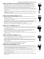
Warning
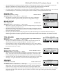
The PROVE input cannot be used as a safety limit. All equipment must have its own
certified
limit
CAUTION:
Risk of
Shock.safety
Lo
Hi Lo
HiElectricand
Use Copper Conductors Only.
controls as required by local codes. No boiler stage will start unless the Prove terminals
are
shorted.
DO NOT
Unit1
Unit2
OUTPUT RATING: 6 AMP RESISTIVE,
PROGRAM
1 AMP PILOT CAUTION:
DUTY PER OUTPUT
Electric Shock.
Stages
Stages RiskATof120VAC.
PWR
remove the PROVE jumper supplied unless replacing it with a Prove signal.
Use Copper Conductors Only.
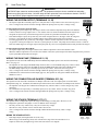
Wiring the System Output (Terminals 19, 20)
DHW COMB.
Stage G Stage H SYSTEM PUMP
AIR
L N
Stage A Stage B Stage C Stage D Stage E Stage F
1 2
AMP PILOT DUTY PER OUTPUT
AT 120VAC.
3 4 5 6 7 8 9 110
11 12 13 14 15 16 17 18
19 20 21 22 23 24
PWR
OUTPUT RATING: 6 AMP RESISTIVE,
L N
DO NOT APP
SE
RUN
PROGRAM
TEMP
RUN
25 26 27 2
DHW COMB.
Stage G Stage H SYSTEM PUMP
AIR
Stage A Stage B Stage C Stage D Stage E Stage F
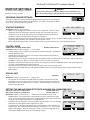
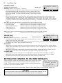
•The System output has a Normally Open (N.O.) relay that acts as a dry-contact. It does not source any power.
CAUTION: Risk of Electric Shock.
L
•Class 1 voltages must enter the enclosure through a different opening from any Class 2 voltage wiring.
Use Copper Conductors Only.
1 2
15 16 17 18 19 20 21 22 23 24
3 4 5 6 7 8 9 10 11 12 13 14
DO
N
OUTPUT RATING: 6 AMP RESISTIVE,
1 AMP PILOT DUTY PER OUTPUT AT 120VAC.
PWR
PROGRAM
L
Stage G Stage HN
SYSTEM
RUN
System Output Operation in Set Point Mode
L N
1 2 drops
3 4 below
5 6 7 8the
9 10
11 12 13 14 15 16 17 18 19 20 21 22 23 24
25
•In Heating, the System output relay will energize whenever the outdoor temperature
Outdoor
System
Cutoff or whenever a stage output is active. If no outdoor sensor is connected and the last boiler relay has dePump
System
energized, the System relay will remain energized for a period set by the Run-On and then de-energize.
L
Pump
•If the PROVE input is Open, the System relay will remain energized however, all stages will be de-energized.
N
If a Prove is not required, the factory-installed jumper must remain connected for proper operation.
•In Cooling applications, the system relay will energize when the outdoor temperature is above the Outdoor Cutoff setting.
•A typical use of the System output is to activate a system pump or its starter. The pumpCAUTION:
can runRisk
whenever
there is a call
for
of Electric Shock.
System
Use Copper Conductors Only.
DO NOT APPLY
Pump
heat/cool. When stages are no longer required, the pump will stay active for an adjustable
Run-On
delay
and then PROGRAM
de-energize.
OUTPUT
RATING: 6 AMP
RESISTIVE,
RUN
SENSO
Stage A Stage B Stage C Stage D Stage E Stage F
DHW COMB.
PUMP
AIR
1 AMP PILOT CAUTION:
DUTY PER OUTPUT
ATof
120VAC.
Risk
Electric
Shock.
Use Copper Conductors Only.
PWR
DHW
COMB.
DO
TEMP
RUN
System Output Operation in Reset Mode
1 2
3 4 5 6 7 8
25 26 27 28
PWR
•The System output relay will energize whenever the outdoor temperature is below Lthe
Outdoor
Cutoff.
N
•When the outdoor temperature rises 2°F above the Outdoor Cutoff, the System output
for
set21 22 23 24
1 2 will
3 remain
4 5 6 7 energized
8 9 10 11 12 13
14 the
15 16period
17 18 19 20
CAUTION: Risk of Electric Shock. L
by the System Run-On and then de-energize.
Use Copper Conductors Only.
Stage G Stage H SYSTEM PUMP
AIR
OUTPUT RATING: 6 AMP RESISTIVE,
PROGRAM
19AMP
PER 15
OUTPUT
120VAC.
16 17AT18
10 PILOT
11 12DUTY
13 14
19 20 21 22 23 24
L N
Stage A Stage B Stage C Stage D Stage E Stage F
N
Line
120VAC L N
Power Source
1 2
Stage A Stage B Stage C Stage D Stage E Stage F
DO NO
PROGRAM
L
DHW
Stage G Stage H SYSTEM
N PUMP
RUN
COMB.
AIR
15 16 17 18 19 20 21 22 23 24
L
N
DHW
Pump
DHW
Pump
Use Copper Conductors Only.
PWR
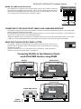
Wiring the Combustion Air Damper (Terminals 23,
L N 24)
25 2
DHW
Pump
Neutral
Line
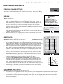
The SQ-Elite-8T can control the DHW Pump when the DHW Pump Output option is activated from the Startup
120VAC
Menu. See page 18.
Power Source
•The SQ-Elite-8T will energize the DHW Pump whenever there is a call for DHW using a dry contact or when
the DHW temperature falls below the DHW Set Point and DHW Differential when using a DHW sensor.
•The DHW Pump output relay is a Normally Open (N.O.) dry contact. It does not source any power.
120VAC
•Class 1 voltages must enter the enclosure through a different opening from any
Class 2 voltage wiring.
Power Source
•If Shutdown was selected as the External Input (page 18), The Sq-Elite-8T will ignore a DHW call when the
CAUTION: Risk of Electric Shock.
Shutdown is active.
3 4 5 6 7 8 9 10 11 12 13 14
DHW COMB.
PUMP
AIR
Stage G Stage H SYSTEM
OUTPUT RATING: 6 AMP RESISTIVE,
1 AMP PILOT DUTY PER OUTPUT AT 120VAC.
PWR
Neutral
Line
Wiring the DHW Pump (Terminals 21, 22)
Neutral
Stage A Stage B Stage C Stage D Stage E Stage F
OUTPUT RATING: 6 AMP RESISTIVE,
PROGRAM
1 AMP PILOT CAUTION:
DUTY PER OUTPUT
ATof
120VAC.
Risk
Electric Shock.
RUN
DO NOT APPL
SEN
Use Copper Conductors Only.
Stage A Stage B Stage C Stage D Stage E Stage F
DHW COMB.
Stage G Stage H SYSTEM PUMP
AIR
OUTPUT RATING: 6 AMP RESISTIVE,
PROGRAM
110
AMP
DUTY
AT 19
120VAC.
16 17 18
11PILOT
12 13
14 PER
15 OUTPUT
20 21 22 23 24
RUN
TEMP
1 2
3 4 5 6 is
7 activated
8 9
25 26 27 28
PWR
The SQ-Elite-8T can control the Combustion Air Damper when the Comb. Air Output
option
in the
N
Startup Menu (Page 18). In addition, the PROVE input will function as the CombustionL Air
Damper status checker.
1 2
3 4 5 6 7 8 9 10 11 12 13 14 15 16 17 18 19 20 21 22 23 24
2
•The SQ-Elite will energize the Combustion Air Damper relay whenever there is a call to energize
any of the
CAUTION: Risk of Electric Shock.
L
Use Copper Conductors Only.
unit stages.
DO N
N
OUTPUT RATING: 6 AMP RESISTIVE,
PROGRAM
RUN
1 AMP PILOT
DUTY PER OUTPUT AT 120VAC.
•The Combustion Air output relay is a Normally Open (N.O.) dry contact. It doesPWR
not
source
any
power.
L
Lo Hi
Lo Hi
L N Unit1
N
•Class 1 voltages must enter the enclosure through a different opening from any Class
2 voltage Unit2
wiring.
Stage A Stage B Stage C Stage D Stage E Stage F
•The relays are N.O. dry contacts only. They do not source any voltage.
L
•Wire the N.O. relay contacts in series with the unit’s limit circuit.
Unit1
•Class 1 voltages must enter the enclosure through a different knockout from any Class 2Pump
voltage
wiring.
N
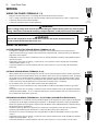
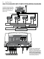
Wiring the Stage Outputs
•Each Stage output (A through H) has one (N.O.) relay.
•When wiring several multi-stage units, start with the lower stage of the first unit and wire it to
Output A, followed by the higher stage of the same unit and wire it to Stage B.
Unit2
Pump
DHW COMB.
Stage G Stage H SYSTEM PUMP
AIR
15 16 17 18 19 20 21 22 23 24
25 2
System Sensor
Stage A Stage B Stage C Stage D Stage E Stage F
3 4 5 6 Stages
11 12 13 14
Stages
Lo Hi7 8 9 10Lo
Hi
Unit1
L
Unit2
StagesUnit2 Stages
Unit1
L
Pump
Pump
Wiring the Stages (Terminals 3 to 17)
Unit2
N
Unit1
LoPump
Hican Lo Pump
Hi
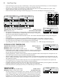
The SQ-Elite can be configured to operate the stages of the heating or cooling units. Moreover,
it
PWR
Unit1
Unit2L N
N
be configured to operate the unit pumps or valves in addition to the unit stages.
Stages
Stages
1 2
1 2
DHW COMB.
Stage G Stage H SYSTEM PUMP
AIR
Comb.
Air
Damper
CAUTION:LRisk ofComb.
Electric Shock.
Use Copper
N Conductors
Air Only.
OUTPUT RATING: 6 AMP
RESISTIVE,
Damper
1 AMP PILOT DUTY PER OUTPUT AT 120VAC
Stage A Stage B Stage C Stage D Stage E Stage F
Stage G S
3 4 5 6 7 8 9 10 11 12 13 14
15 16 1
Comb.
Air
Damper
Lo Hi Lo Hi
Unit1 Unit2
Stages Stages
CAUTION: Risk of Electric Shock.
Use Copper Conductors Only.
OUTPUT RATING: 6 AMP RESISTIVE,
1 AMP PILOT DUTY PER OUTPUT AT 120VAC