1
User Manual
FieldForce TRAX
Attitude & Heading Reference System (AHRS)
Table of Contents
1 COPYRIGHT & WARRANTY INFORMATION .................................................. 1
2 INTRODUCTION........................................................................................... 2
3 SPECIFICATIONS .......................................................................................... 3
3.1
Characteristics & Requirements ............................................................3
3.2
Mechanical Drawings .............................................................................5
4 SET-UP ........................................................................................................ 7
4.1
Electrical Connections ............................................................................7
4.2
Installation Location...............................................................................8
4.2.1
Operate within the Trax’s dynamic range ....................................8
4.2.2
Locate away from changing magnetic fields.................................8
4.2.3
Mount in a physically stable location ...........................................8
4.3
Mechanical Mounting ............................................................................8
4.3.1
Pitch and Roll Convention .............................................................8
4.3.2
Mounting Orientation ...................................................................9
5 CALIBRATION ............................................................................................ 11
5.1
Magnetic Calibration........................................................................... 12
5.1.1
Full Range Calibration ................................................................ 13
5.1.2
2D Calibration ............................................................................ 15
5.1.3
Limited Tilt Range Calibration .................................................... 16
5.1.4
Hard Iron Only Calibration ......................................................... 17
5.2
Accelerometer Calibration .................................................................. 17
6 GETTING STARTED WITH TRAX STUDIO ..................................................... 19
6.1
Installation .......................................................................................... 19
6.2
Trax Studio Header and Connecting to Trax Studio............................ 19
6.3
Trax Studio Footer and Saving/Applying Settings............................... 20
6.4
Configuration Tab ............................................................................... 21
6.4.1
General Settings ......................................................................... 22
6.4.2
Acquisition Settings.................................................................... 23
6.5
Calibration and the Calibration Tab .................................................... 24
6.5.1
Calibration Settings .................................................................... 24
6.5.2
Performing a Calibration ............................................................ 26
6.5.3
Calibration Results ..................................................................... 26
6.6
Test Tab ............................................................................................... 28
6.7
Log Data Tab ....................................................................................... 30
6.8
Graph Tab............................................................................................ 31
6.9
System Log Tab ................................................................................... 32
PNI Sensor Corporation
TRAX User Manual – March 2012
DOC#1016505 r05
Page i
7 OPERATION WITH PNI BINARY PROTOCOL ................................................ 33
7.1
Datagram Structure ............................................................................ 33
7.2
Parameter Formats ............................................................................. 34
7.3
Commands Overview .......................................................................... 36
7.4
Set-Up Commands .............................................................................. 37
7.4.1
Module Information................................................................... 37
7.4.2
Module Configuration ................................................................ 38
7.4.3
Saving Settings ........................................................................... 42
7.5
Measurement Commands .................................................................. 43
7.5.1
Setting the Reference Magnetic Field Criteria........................... 43
7.5.2
Data Acquisition Parameters ..................................................... 43
7.5.3
Data Components ...................................................................... 44
7.5.4
Making a Measurement ............................................................. 46
7.6
Calibration Commands........................................................................ 47
7.6.1
User Calibration Commands ...................................................... 47
7.6.2
Performing a User calibration .................................................... 49
7.6.3
Calibration Score ........................................................................ 50
7.6.4
Factory Calibration ..................................................................... 51
7.7
Compass Mode Commands ................................................................ 51
7.7.1
Switching Functional Mode ....................................................... 51
7.7.2
FIR Filters.................................................................................... 52
7.7.3
Power Down/Up ........................................................................ 54
List of Figures
Figure 3-1:
Figure 3-2:
Figure 3-3:
Figure 3-4:
Figure 3-5:
Figure 3-6:
Figure 4-1:
Figure 4-2:
Figure 5-1:
Figure 5-2:
Figure 7-1:
Typical Current Drawing During Application of External Power ..........4
Trax PCA Mechanical Drawing ..............................................................5
PNI Pigtailed Molex Cable Drawing ......................................................5
Trax Enclosed Mechanical Drawing ......................................................6
Trax USB Cable Drawing .......................................................................6
Trax RS232 Cable Drawing ....................................................................6
Positive & Negative Roll and Pitch Definition .......................................9
Trax Enclosed Mounting Orientations ............................................... 10
12 Point Full Range Calibration.......................................................... 14
Accelerometer Calibration Starting Orientations .............................. 18
Datagram Structure ........................................................................... 33
TRAX User Manual r05
Page ii
List of Tables
Table 3-1:
Table 3-2:
Table 3-3:
Table 3-4:
Table 3-5:
Table 4-1:
Table 5-1:
Table 5-2:
Table 5-3:
Table 5-4:
Table 5-5:
Table 7-1:
Table 7-2:
Table 7-3:
Table 7-4:
Table 7-5:
Table 7-6:
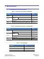
Performance Specifications in AHRS Mode ...........................................3
Performance Specifications in Compass Mode .....................................3
I/O Characteristics..................................................................................3
Environmental Requirements ................................................................4
Mechanical Characteristics ....................................................................4
Trax Pin Descriptions..............................................................................7
Magnetic Calibration Mode Summary ................................................ 13
12 Point Full Range Calibration Pattern .............................................. 15
12 Point 2D Calibration Pattern .......................................................... 16
12 Point Limited Tilt Calibration Pattern ............................................ 16
6 Point Hard Iron Only Calibration Pattern ......................................... 17
Communication Port Configuration .................................................... 33
Trax Binary Command Set ................................................................... 36
Configuration Identifiers ..................................................................... 39
Sample Points...................................................................................... 40
Component Identifiers ........................................................................ 45
Recommended FIR Filter Tap Values .................................................. 53
PNI Sensor Corporation
TRAX User Manual – March 2012
DOC#1016505 r05
Page iii of 60
1 Copyright & Warranty Information
© Copyright PNI Sensor Corporation 2011
All Rights Reserved. Reproduction, adaptation, or translation without prior written permission is prohibited, except
as allowed under copyright laws.
Revised March 2012. For most recent version visit our website at www.pnicorp.com
PNI Sensor Corporation
133 Aviation Blvd, Suite 101
Santa Rosa, CA 95403, USA
Tel: (707) 566-2260
Fax: (707) 566-2261
Warranty and Limitation of Liability. PNI Sensor Corporation ("PNI") manufactures its Trax products (“Products”)
from parts and components that are new or equivalent to new in performance. PNI warrants that each Product to be
delivered hereunder, if properly used, will, for one year following the date of shipment unless a different warranty
time period for such Product is specified: (i) in PNI’s Price List in effect at time of order acceptance; or (ii) on PNI’s
web site (www.pnicorp.com) at time of order acceptance, be free from defects in material and workmanship and will
operate in accordance with PNI’s published specifications and documentation for the Product in effect at time of
order. PNI will make no changes to the specifications or manufacturing processes that affect form, fit, or function of
the Product without written notice to the OEM, however, PNI may at any time, without such notice, make minor
changes to specifications or manufacturing processes that do not affect the form, fit, or function of the Product. This
warranty will be void if the Products’ serial number, or other identification marks have been defaced, damaged, or
removed. This warranty does not cover wear and tear due to normal use, or damage to the Product as the result of
improper usage, neglect of care, alteration, accident, or unauthorized repair.
THE ABOVE WARRANTY IS IN LIEU OF ANY OTHER WARRANTY, WHETHER EXPRESS, IMPLIED, OR
STATUTORY, INCLUDING, BUT NOT LIMITED TO, ANY WARRANTY OF MERCHANTABILITY,
FITNESS FOR ANY PARTICULAR PURPOSE, OR ANY WARRANTY OTHERWISE ARISING OUT OF ANY
PROPOSAL, SPECIFICATION, OR SAMPLE. PNI NEITHER ASSUMES NOR AUTHORIZES ANY PERSON
TO ASSUME FOR IT ANY OTHER LIABILITY.
If any Product furnished hereunder fails to conform to the above warranty, OEM’s sole and exclusive remedy and
PNI’s sole and exclusive liability will be, at PNI’s option, to repair, replace, or credit OEM’s account with an
amount equal to the price paid for any such Product which fails during the applicable warranty period provided that
(i) OEM promptly notifies PNI in writing that such Product is defective and furnishes an explanation of the
deficiency; (ii) such Product is returned to PNI’s service facility at OEM’s risk and expense; and (iii) PNI is satisfied
that claimed deficiencies exist and were not caused by accident, misuse, neglect, alteration, repair, improper
installation, or improper testing. If a Product is defective, transportation charges for the return of the Product to
OEM within the United States and Canada will be paid by PNI. For all other locations, the warranty excludes all
costs of shipping, customs clearance, and other related charges. PNI will have a reasonable time to make repairs or
to replace the Product or to credit OEM’s account. PNI warrants any such repaired or replacement Product to be
free from defects in material and workmanship on the same terms as the Product originally purchased.
Except for the breach of warranty remedies set forth herein, or for personal injury, PNI shall have no liability for any
indirect or speculative damages (including, but not limited to, consequential, incidental, punitive and special
damages) relating to the use of or inability to use this Product, whether arising out of contract, negligence, tort, or
under any warranty theory, or for infringement of any other party’s intellectual property rights, irrespective of
whether PNI had advance notice of the possibility of any such damages, including, but not limited to, loss of use,
revenue or profit. In no event shall PNI’s total liability for all claims regarding a Product exceed the price paid for
the Product. PNI neither assumes nor authorizes any person to assume for it any other liabilities.
Some states and provinces do not allow limitations on how long an implied warranty lasts or the exclusion or
limitation of incidental or consequential damages, so the above limitations or exclusions may not apply to you. This
warranty gives you specific legal rights and you may have other rights that vary by state or province.
PNI Sensor Corporation
TRAX User Manual – March 2012
DOC#1016505 r05
Page 1 of 60
2 Introduction
Thank you for purchasing PNI Sensor Corporation’s Trax attitude & heading reference system
(AHRS). The Trax employs a proprietary Kalman filtering algorithm that intelligently fuses
PNI's patented Reference Magnetic Sensors with a 3-axis gyroscope and 3-axis accelerometer.
The result is an orientation device that provides accurate heading information under a wide
variety of conditions, including its ability to overcome errors normally caused by erratic motion
and/or changes in the local magnetic field. The advanced features of the Trax make it ideal for a
variety of applications, including:
Unmanned Ground Vehicles (UGV) – Robots and Unmanned Conversions
Unmanned Underwater Vehicles (UUV) – Autonomous Gliders and ROV’s
We’re sure the Trax will help you to achieve the greatest performance from your system. Thank
you for selecting the Trax.
TRAX User Manual r05
Page 2 of 60
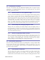
3 Specifications
3.1 Characteristics & Requirements
Table 3-1: Performance Specifications in AHRS Mode1
Parameter
Value
Accuracy2
Resolution
Heading
Pitch
Roll
Range
Attitude
Power
Consumption
Accuracy
Resolution
Average Current Draw @ Maximum Sample Rate
Current Draw During Application of External Power
2.0° rms
0.1°
± 90°
± 180°
2.0° rms
0.01°
55 mA
See Figure 3-1
Table 3-2: Performance Specifications in Compass Mode1
Parameter
Value
3
Static Accuracy
Resolution
Repeatability
Heading
Range
Attitude
Power
Consumption
Pitch
Roll
Static Accuracy
Resolution
Repeatability
Average Current Draw @ Maximum Sample Rate
Sleep Mode Current Draw
0.3° rms
0.1°
0.05° rms
± 90°
± 180°
0.2° rms
0.01°
0.05° rms
28 mA
0.5 mA
Table 3-3: I/O Characteristics
Parameter
Value
Supply Voltage
Communication Interface
Communication Protocol
Communication Rate4
Maximum Data Output Rate
3.6 to 5 VDC
RS232 UART & USB
PNI Binary
2400 to 921,600 baud
≈30 samples/sec
PNI Sensor Corporation
TRAX User Manual – March 2012
DOC#1016505 r05
Page 3 of 60
Table 3-4: Environmental Requirements
Parameter
Value
Operating Temperature
Storage Temperature
5
-40C to +85C
-40C to +85C
Table 3-5: Mechanical Characteristics
Parameter
Dimensions
(l x w x h)
Weight
Connector
Value
Trax Enclosed
Trax PCA
Trax Enclosed
Trax PCA
Trax Enclosed
Trax PCA
6.4 x 5.9 x 2.3 cm
3.5 x 4.3 x 1.3 cm
75 gm
7 gm
7 pin ODU, pn K20L0C-P07LCC0-520S
9-pin Molex, pn 53780-0970
Footnotes to Tables:
1. Specifications are typical unless otherwise noted, and subject to change.
2. Assumes heading status is “1”. See Section 6.6 or Section 7.5.3
3. Assumes Trax is motionless and the local magnetic field is clean relative to user calibration.
4. The Trax can operate up to 921,600 baud, but native RS232 is limited to 115,200 baud.
5. To meet performance specifications across this range, recalibration will be necessary as the
temperature varies.
Figure 3-1: Typical Current Drawing During Application of External Power
TRAX User Manual r05
Page 4 of 60
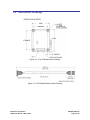
3.2 Mechanical Drawings
Figure 3-2: Trax PCA Mechanical Drawing
Figure 3-3: PNI Pigtailed Molex Cable Drawing
PNI Sensor Corporation
TRAX User Manual – March 2012
DOC#1016505 r05
Page 5 of 60
Figure 3-4: Trax Enclosed Mechanical Drawing
Figure 3-5: Trax USB Cable Drawing
Figure 3-6: Trax RS232 Cable Drawing
TRAX User Manual r05
Page 6 of 60
4 Set-Up
This section describes how to configure the Trax in your host system. To install the Trax into
your system, follow these steps:
Make electrical connections to the Trax.
Evaluate the Trax using the Trax Studio program, or a binary terminal emulation
program, such as RealTerm or Tera Term, to ensure the Trax is working properly.
Choose a mounting location.
Mechanically mount the Trax in the host system.
Perform a user calibration.
4.1 Electrical Connections
The enclosed version of Trax incorporates a pigtailed 7 pin ODU connector, part number
K20L0C-P07LCC0-560S, which mates with ODU part S20L0C-T07MCC0-560S or
equivalent. The Trax PCA incorporates a 9 pin Molex connector, part number 53780-0970,
which mates with Molex part 51146-0900 or equivalent. The pin-out for both is given below
in Table 4-1.
Table 4-1: Trax Pin Descriptions
Trax Enclosed
1
Pin #
Trax PCA
Pigtailed 7 Pin
Connector*
9 Pin Molex
Connector
PNI Cable
Wire Color
USB D+
RS232 +5 VDC
RS232 Tx
RS232 Rx
USB + 5 VDC
USB D– A
Ground
Ground
USB +5 VDC
Ground
Not Connected
USB D–
USB D+
RS232 Tx
RS232 Rx
RS232 +5 VDC
Black
Gray
Green
Orange
Violet
Brown
Yellow
Blue
Red
1
2
3
4
5
6
7
8
9
Footnote:
1. For the Trax Enclosed, pin #1 is the first pin to the left of the key, and
numbering runs counter-clockwise from pin #1, with pin #7 in the middle.
For the Trax PCA, pin #1 is indicated on Figure 3-2.
After making the electrical connections, it is a good idea to perform some simple tests to
ensure the Trax is working as expected. See Section 6 for how to operate the Trax with Trax
Studio or Section 7 for how to operate the Trax using PNI’s binary protocol.
PNI Sensor Corporation
TRAX User Manual – March 2012
DOC#1016505 r05
Page 7 of 60
4.2 Installation Location
The Trax’s wide dynamic range and sophisticated algorithms allow it to operate in many
environments. For optimal performance however, you should mount the Trax with the
following considerations in mind:
4.2.1
Operate within the Trax’s dynamic range
The Trax can be field calibrated to correct for static magnetic fields created by the host
system. However, each axis of the Trax has a calibrated dynamic range of ±125 µT. If
the total field exceeds this value for any axis, the Trax may not perform to specification.
When mounting the Trax, consider the effect of any sources of magnetic fields in the host
environment that, when added to Earth’s field, may take the Trax out of its dynamic
range. For example, large masses of ferrous metals such as transformers and vehicle
chassis, large electric currents, permanent magnets such as electric motors, and so on.
4.2.2
Locate away from changing magnetic fields
While the Trax can compensate for transient changes in the local magnetic field, it is
good design practice to keep the Trax away from sources of local magnetic distortion that
knowingly will change with time; such as electrical equipment that will be turned on and
off, or ferrous bodies that will move.
4.2.3
Mount in a physically stable location
Choose a location that is isolated from persistent vibration or other dynamic motion. The
Trax can provide accurate headings while experiencing intermittent dynamic motion,
such as vibration or quick heading changes. But if this is persistent the Trax will have
difficulty holding an accurate heading over extended periods of time.
4.3 Mechanical Mounting
The Trax is factory calibrated with respect to its mounting holes. It must be aligned within
the host system with respect to these mounting holes. Ensure any stand-offs or screws used
to mount the Trax are non-magnetic. Refer to Section 3.2 for dimensions, hole locations, and
the reference frame orientation.
4.3.1
Pitch and Roll Convention
The Trax utilizes Euler angles as the primary method for providing orientation data,
although quaternions outputs also are available. The Euler angles are the common
method used for aircraft orientation, where the outputs are heading, pitch and roll. When
TRAX User Manual r05
Page 8 of 60
using Euler angles in aviation, roll is defined as the angle rotated around an axis through
the center of the fuselage, while pitch is rotation around an axis through the center of the
wings. These rotations are dependent on each other since the axes of rotation move with
the plane.
As shown in Figure 4-1, for the Trax a positive pitch is when the front edge of the board
is rotated upward and a positive roll is when the right edge of the board is rotated
downward. The order of rotation is given as heading, pitch, and then roll.
Figure 4-1: Positive & Negative Roll and Pitch Definition
4.3.2
Mounting Orientation
The Trax can be mounted in 16 different orientations, as shown for the enclosed version
of the Trax in Figure 4-2. All reference points are based on the silk-screened arrow on
the cover of the enclosed version of the Trax, or on top side of the Trax PCA board. The
orientation should be programmed in the Trax using the Configuration Tab in Trax
Studio or using the kSetConfig command and the kMountingRef setting in the PNI
Protocol, as described in Section 7.4.2. The default orientation is “STD 0°”.
PNI Sensor Corporation
TRAX User Manual – March 2012
DOC#1016505 r05
Page 9 of 60
Figure 4-2: Trax Enclosed Mounting Orientations
TRAX User Manual r05
Page 10 of 60
5
Calibration
To optimize the performance of the Trax such that it performs to specification it is necessary to
properly calibrate both the magnetic sensors and the accelerometers in the device.
The magnetic sensors in the Trax are calibrated at PNI’s factory in a magnetically controlled
environment. However sources of magnetic distortion positioned near the Trax in the user’s
system will distort Earth’s magnetic field and should be compensated for in the host system with
a user calibration. Examples of such sources include ferrous metals and alloys (ex. iron, nickel,
steel, etc.), batteries, audio speakers, current-carrying wires, and electric motors. Compensation
is accomplished by mounting the Trax in the host system and performing a user calibration. It is
expected the sources of magnetic distortion remain fixed relative to the Trax’s position within
the host system. By performing a calibration, the Trax identifies the local sources of magnetic
distortion and negates their effects from the overall reading to provide an accurate heading.
As with the magnetic sensors, the accelerometers in the Trax are calibrated at PNI’s factory. But
the accelerometers gradually change over time, and the user either will need to periodically
perform a user accelerometer calibration or return the unit to PNI for recalibration. As a rule-ofthumb, the accelerometers should be recalibrated every 6 to 12 months. Unlike a magnetic
calibration, the accelerometers may be calibrated outside the host system. Accelerometer
calibration is more sensitive to noise or hand jitter than magnetic calibration, especially for
subsequent use at high tilt angles. Because of this, a stabilized fixture is suggested for
accelerometer calibration, although resting the unit against a stable surface often is sufficient.
Key Points:
User calibration is required for the Trax to perform optimally and meet specification.
Magnetometer calibration:
o Requires incorporating the Trax into the user’s host system such that the magnetic
components of the user’s system can be compensated for.
o Allows for 4 different methods of calibration. Full Range Calibration provides
the highest heading accuracy, but requires ≥45° of pitch during calibration. 2D
and Limited Tilt Calibration allow for good calibration when the range of
allowable motion is limited. Hard Iron Only Calibration updates the hard-iron
compensation coefficients with a relatively easy procedure.
Accelerometer calibration requires rotating the Trax through a full sphere of coverage,
but the Trax does not need to be incorporated into the user’s system during calibration.
PNI Sensor Corporation
TRAX User Manual – March 2012
DOC#1016505 r05
Page 11 of 60
5.1
Magnetic Calibration
Two fundamental types of magnetic distortion exist: hard iron and soft iron. These are
discussed in the following paragraphs, plus a discussion on how temperature effects magnetic
fields and other considerations. For more information on magnetic distortion and calibration,
see PNI’s white paper “Local Magnetic Distortion Effects on 3-Axis Compassing” at PNI’s
website (http://www.pnicorp.com/technology/papers).
Hard Iron Effects
Hard iron distortions are caused by permanent magnets and magnetized steel or iron
objects within close proximity to the sensors. This type of distortion remains constant
and in a fixed location relative to the sensors for all heading orientations. Hard-iron
distortions add a constant magnitude field component along each axis of sensor
output.
Soft Iron Effects
Soft-iron distortions are the result of interactions between the Earth’s magnetic field
and any magnetically “soft” material within close proximity to the sensors. In
technical terms, soft materials have a high permeability. The permeability of a given
material is a measure of how well it serves as a path for magnetic lines of force,
relative to air, which has an assigned permeability of one. Unlike hard-iron
distortion, soft-iron distortion changes as the host system’s orientation changes,
making it more difficult to compensate.
Temperature Effects
While the hard iron and soft iron distortions of a given component in a system may
remain quite stable over time, normally this distortion signature will change over
temperature. Therefore, no matter how stable a compass is over temperature, it is
usually necessary to recalibrate as the temperature changes since the magnetic
distortion signature of the host system will change over temperature. One way the
Trax helps with this issue is by allowing the user to save up to 8 sets of calibration
coefficients, so that as the temperature changes a magnetic calibration coefficient set
matching the new temperature can be used in the Trax.
Other Considerations
The Trax measures the total magnetic field within its vicinity, and this is a
combination of Earth’s magnetic field and local magnetic sources. The Trax can
compensate for local static magnetic sources. However, a magnetic source which is
not static, such as a motor which turns on/off, can create errors and it is not possible
to compensate for such a dynamic nature. In such cases, keeping the Trax away from
dynamic magnetic fields is recommended, or taking measurements only when the
TRAX User Manual r05
Page 12 of 60
state of the magnetic field is know. For example, only take measurements when a
nearby motor is turned off.
The main objective of a magnetic user calibration is to compensate for hard iron and soft iron
distortions to the magnetic field caused by components within the user’s host system. To that
end, the Trax needs to be mounted within the host system and the entire host system needs to
be moved as a single unit during a user calibration. The Trax allows the user to perform a
calibration only in a 2D plane or with limited tilt, but provides the greatest accuracy if the
user can rotate through a full sphere.
The following subsections provide instructions for performing a magnetic calibration of a
Trax system. Calibration may be performed using Trax Studio or using the PNI binary
protocol, and up to 8 sets of calibration coefficients may be saved. The recommended
calibration patterns described in the following sub-sections provide a good distribution of
sample points. Also, PNI recommends the location of the Trax remain fairly constant while
only the orientation is changed.
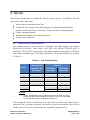
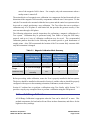
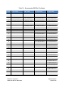
Table 5-1: Magnetic Calibration Mode Summary
Calibration
Mode
Full Range
2D Calibration
Limited Tilt
Range
Hard Iron Only
Static Accuracy in Tilt Range
Compass Mode
during Cal
# of Samples in
Recommended
Cal Pattern
Allowable
Range of #
of Samples
10 – 18
10 – 18
10 – 18
0.3° rms
<2°
>±45°
<±5°
12
12
<2° over 2x tilt range
±5° to ±45°
12
Restores prior
accuracy
>±3°
6
4 - 18
Before proceeding with a calibration, ensure the Trax is properly installed in the host system.
The device should be installed as discussed in Section 4, and the software should be properly
configured with respect to the mounting orientation, Endianness, north reference, etc.
Section 6.5 outlines how to perform a calibration using Trax Studio, while Section 7.6.2
provides a step-by-step example of how to perform a calibration using the PNI protocol.
5.1.1
Full Range Calibration
A Full Range Calibration is appropriate when the Trax can be tilted ±45° or more. This
method compensates for hard and soft iron effects in three dimensions, and allows for the
highest accuracy readings.
PNI Sensor Corporation
TRAX User Manual – March 2012
DOC#1016505 r05
Page 13 of 60
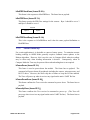
The recommended 12 point calibration pattern is a series of 3 circles of evenly spaced
points, as illustrated in Figure 5-1 and listed in Table 5-2. The pitch used in the second
and third circles of the calibration should at least match the maximum and minimum
pitch the device is expected to encounter in use.
Figure 5-1: 12 Point Full Range Calibration
Note: While Figure 5-1 shows the location of the device changing, this is for illustration
purposes and it is best for the location of the device to remain constant while only the
orientation is changed.
TRAX User Manual r05
Page 14 of 60
Table 5-2: 12 Point Full Range Calibration Pattern
Sample #
Yaw 1
Pitch
Roll
0°
90°
180°
270°
±5°
±5°
±5°
±5°
30° to 40°
-30° to -40°
30° to 40°
-30° to -40°
30°
120°
210°
300°
> +45°
> +45°
> +45°
> +45°
30° to 40°
-30° to -40°
30° to 40°
-30° to -40°
60°
150°
240°
330°
< -45°
< -45°
< -45°
< -45°
30° to 40°
-30° to -40°
30° to 40°
-30° to -40°
First Circle
1
2
3
4
Second Circle
5
6
7
8
Third Circle
9
10
11
12
Footnote:
1. Yaw listings are not absolute heading directions but rather relative heading
referenced to the first sample.
5.1.2
2D Calibration
A 2D Calibration is intended for very low tilt operation (<5°) where calibrating the Trax
with greater tilt is not practical.
This procedure calibrates for hard and soft iron effects in only two dimensions, and in
general is effective for operation and calibration in the tilt range of -5° to +5°. The
recommended 12 point calibration pattern is a circle of evenly spaced points, as given in
Table 5-3.
PNI Sensor Corporation
TRAX User Manual – March 2012
DOC#1016505 r05
Page 15 of 60
Table 5-3: 12 Point 2D Calibration Pattern
Sample #
Yaw
Pitch1
Roll1
1
2
3
4
5
6
7
8
9
10
11
12
0°
30°
60°
90°
120°
150°
180°
210°
240°
270°
300°
330°
0°
max. negative
0°
max. positive
0°
max. negative
0°
max. positive
0°
max. negative
0°
max. positive
0°
max. negative
0°
max. positive
0°
max. negative
0°
max. positive
0°
max. negative
0°
max. positive
Footnote:
1. For best results, the tilt experienced during calibration should match that experienced
in service. For example, if the Trax is restrained to a level plane in service, then
calibration should be in a plane, where “max. positive” and “max. negative” are 0°.
5.1.3
Limited Tilt Range Calibration
A Limited Tilt Range Calibration is recommended when 45° of tilt isn’t feasible, but >5°
of tilt is possible. It provides both hard iron and soft iron distortion correction. The
recommended 12 point calibration pattern given below is a series of 3 circles of evenly
spaced points, with as much tilt variation as expected during use.
Table 5-4: 12 Point Limited Tilt Calibration Pattern
Sample #
First Circle
1
2
3
6
Second Circle
7
8
11
12
Third Circle
13
14
17
18
TRAX User Manual r05
Yaw
Pitch
Roll
0°
90°
180°
270°
0°
0°
0°
0°
0°
0°
0°
0°
45°
135°
225°
315°
> +5°
> +5°
> +5°
> +5°
> +5°
> +5°
> +5°
> +5°
45°
135°
225°
315°
< -5°
< -5°
< -5°
< -5°
< -5°
< -5°
< -5°
< -5°
Page 16 of 60
Note that a similar and acceptable alternative pattern would be to follow the
recommended 12 point Full Range Calibration pattern, but substituting the >±45° of pitch
with whatever pitch can be achieved and the ±10° to ±20° of roll with whatever roll can
be achieved up to these limits. See Section 5.1.1 for more information.
5.1.4
Hard Iron Only Calibration
It is not uncommon for the hard-iron magnetic distortions around the Trax to change.
Some reasons for this include significant temperature change or temperature shock to a
system, as well as gradual aging of components. A Hard Iron Only Calibration allows for
quick recalibration of the Trax for hard-iron effects, and generally is effective for
operation and calibration in the tilt range of 3° or more (≥45° is preferred). The
recommended 6 point calibration pattern given below is a circle of alternately tilted,
evenly spaced points, with as much tilt as expected during use.
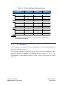
Table 5-5: 6 Point Hard Iron Only Calibration Pattern
Sample #
Yaw
Pitch1
Roll1
1
2
3
4
5
6
0°
60°
120°
180°
240°
300°
max. negative
max. positive
max. negative
max. positive
max. negative
max. positive
max. negative
max. positive
max. negative
max. positive
max. negative
max. positive
Footnote:
1. For best results, the tilt experienced during calibration should match that experienced
in service. For example, if the Trax will be subject to ±45° of pitch and roll when in
service, then “max negative” should be -45° and “max positive” should be +45°.
5.2 Accelerometer Calibration
The Trax uses MEMS accelerometers to measure the attitude (pitch and roll) of the compass.
This data is output as pitch and roll data. Additionally, the accelerometer data is critical for
establishing an accurate heading reading when the Trax is tilted, as discussed in the PNI
white paper “Tilt-Induced Heading Error in a 2-Axis Compass”, which can be found on
PNI’s web site (http://www.pnicorp.com/technology/papers).
As previously mentioned, PNI calibrates the accelerometers in its factory prior to shipment.
But over time the bias and offset of the accelerometers will drift. For this reason PNI
PNI Sensor Corporation
TRAX User Manual – March 2012
DOC#1016505 r05
Page 17 of 60
recommends the accelerometers be recalibrated every 6 to 12 months. The user may return
the Trax to PNI for accelerometer calibration, or the user may perform a user accelerometer
calibration. The remainder of this section covers the user accelerometer calibration.
The requirements for a good user accelerometer calibration differ significantly from the
requirements for a good magnetic calibration. Specifically, a good accelerometer calibration
involves the Trax experiencing a wide range of pitch and roll values, preferably seeing both
±180° of pitch and ±180° of roll. Also, it is necessary that the Trax be held very still during
an accelerometer calibration. If possible, PNI recommends using a fixture to hold the device
during calibration, although resting the Trax on a hard surface normally is sufficient. On the
other hand, the Trax does not need to be incorporated in the user’s host system to perform a
user accelerometer calibration, which significantly simplifies calibration when compared to
magnetic calibration.
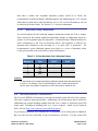
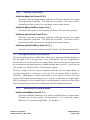
Figure 5-2 shows the two basic starting positions for the recommended 18-point calibration
pattern. Starting with the Trax as shown on the left in Figure 5-2, rotate the device about its
z axis such that it sits on each of its 4 edges, taking one calibration sample on each edge.
Then place the Trax flat on the surface and take a calibration sample, then flip it over (roll it
180°) and take another sample. Next, starting with the Trax as shown on the right, take a
calibration point with it being vertical (0°). Now tilt the Trax back 45° and take another
calibration point (+45°), then tilt the device forward 45° and take another calibration point (45°). Repeat this 3-point calibration process for the Trax with it resting on each of its 4
corners. Note that it is possible to perform an Accelerometer Calibration with as few as 12
sample points, although it generally is more difficult to obtain a good calibration with just 12
sample points. Also, the maximum number of calibration points is 18.
Figure 5-2: Accelerometer Calibration Starting Orientations
TRAX User Manual r05
Page 18 of 60
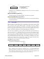
6 Getting Started with Trax Studio
The Trax Studio program puts an easy-to-use, graphical-user interface (GUI) onto the binary
command language used by the Trax. Trax Studio is intended for evaluating, demonstrating, and
calibrating the enclosed version of Trax (“Trax Enclosed”). Among other features, the program
can log and save the outputs from the Trax to a file for off-line evaluation. Anything that can be
done using Trax Studio also can be done using PNI’s binary protocol, as discussed in Section 7.
6.1 Installation
Trax Studio is provided as an executable program which can be downloaded from PNI’s
website. It will work with Windows XP, Windows Vista, and Windows 7 operating systems.
Check the PNI web page at www.pnicorp.com for the latest version.
Copy the “TraxStudio.msi” file onto your computer. Double-click on the icon and step
through the Setup Wizard. The program will be installed into the following directory unless
you direct it otherwise: Program Files\PNI Sensor Corporation\TRAX Studio\. A “Trax
Studio” shortcut icon will be placed on your computer’s desktop.
Now plug the Trax into the USB port of your computer. Ensure the Trax is completely still
when plugging it into the USB port, as the gyros initialize during the first five seconds
after being plugged in.
If you are using the Windows XP operating system, then the first time you plug in the Trax
device it will launch the Found New Hardware Wizard. Select a “Yes…” button, then click
on <Next> and proceed with the installation. The computer should find the required virtual
communications port (VCP) driver by searching the internet, which may take a minute or
two. If you are using Windows 7 the computer automatically searches for and installs the
driver. If there is a problem with this, download the driver from FTDI’s website at
http://www.ftdichip.com/Drivers/VCP.htm.
You have now completed the installation of Trax Studio.
6.2 Trax Studio Header and Connecting to Trax Studio
If the Trax is not already plugged into the computer, then do so. Note that the module must
be motionless when being plugged in and for 5 seconds afterwards, as this is when the gyros
initialize.
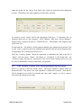
Double-click on the Trax Studio icon to launch Trax Studio. Below is a picture of the Trax
Studio header. The header includes “Module Information” and “Connection Settings”, and
PNI Sensor Corporation
TRAX User Manual – March 2012
DOC#1016505 r05
Page 19 of 60
under the header are the various Trax Studio tabs, which are discussed in the subsequent
sections. The header is the same regardless of which tab is selected.
To connect, set the “Serial” field to the appropriate COM port. To determine this, in
Windows right click on “My Computer”, select “Manage”, then select “Device Manager”.
Expand “Ports” and note the port for “USB Serial Port”. This should be the assigned COM
port for the Trax.
Set the baud rate. The default is 38400, and this should be the setting the first time the Trax
is used. Once a connection has been established, the desired baud rate can be changed on the
Configuration Tab, as discussed in Section 6.4.1.
Click the <Connect> button. When the connection is established, the light to the left of
“Status” will turn green, “Status” will change to “Connected @ [the baud rate]”, the
<Connect> button will now say <Disconnect>, the <Power Down> button will be live, and
the “Device Information” section of the header will populate.
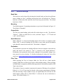
6.3 Trax Studio Footer and Saving/Applying Settings
Below is a picture of the Trax Studio footer. The footer includes 4 buttons which are
discussed below. The footer is the same regardless of which tab is selected. Note that if a
field is changed on any of the Trax Studio tabs, then either <Apply> or <Save> must be
selected for the change to take effect.
TRAX User Manual r05
Page 20 of 60
Save
Clicking the <Save> button will save any changes made in Trax Studio to the Trax’s
onboard non-volatile and volatile memory.
Apply
Selecting the <Apply> button will apply any changes to the Trax’s volatile memory,
but not to the non-volatile memory. If the Trax is powered off/on, the settings will
revert to whatever was last saved in the non-volatile memory.
Read
Clicking the <Read> button will read the current settings in the Trax’s volatile
memory and display them. This will change any item in bold, which indicates a
setting was changed in Trax Studio but not applied to the Trax’s volatile memory,
back to regular type and the setting change will not be applied to the Trax’s memory.
Default
Selecting the <Default> button will display the default settings, which are stored in
Trax Studio. Selecting this button will not automatically apply these values, and
either <Apply> or <Save> must be selected for the read values to be applied.
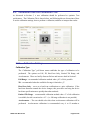
6.4 Configuration Tab
The Configuration Tab is shown below and its contents discussed in the following
subsections. For any changes to take effect, the <Save> button must be selected. Clicking
on the <Default> button will load the factory default values, although these must be saved to
take effect. Clicking the <Retrieve> button will show the current settings of the device.
PNI Sensor Corporation
TRAX User Manual – March 2012
DOC#1016505 r05
Page 21 of 60
6.4.1
General Settings
Baud Rate
The baud rate can be altered by selecting the desired baud rate from the pull down
menu, clicking on “Save”, and then powering the device off and back on. The new
baud rate will not take effect until the device has been powered off/on. The default
baud rate is 38400.
Mounting
Trax Studio supports 16 mounting orientations, as previously illustrated in Figure 4-2.
The default is “Standard”.
Output Units
The Trax can output heading, pitch, and roll in either degrees or mils. The default is
“Degrees”. (There are 6400 mils in a circle, such that 1 degree = 17.7778 mils and
1 mil = 0.05625 degree.)
North Reference
When “Magnetic” is selected, the heading output will be relative to magnetic north.
When “True” is selected, heading will be relative to true north, and the declination
value should be entered in the next field. The default is “Magnetic”.
Declination
The declination represents the heading difference between magnetic north and true
north, and needs to be entered if “True” is selected as the “North Reference”.
Declination varies primarily with location, although it also gradually changes over
time (years) for a given location. To find the declination for where the Trax will be
used, go to http://www.ngdc.noaa.gov/geomagmodels/Declination.jsp.
Filter Taps
When operating the Trax in Compass Mode, the Trax will use a finite impulse
response (FIR) filter to effectively provide a stable heading reading. When operating
in AHRS Mode a completely different filtering method is used and the number of FIR
Taps is not relevant.
The number of taps (or samples) represents the amount of filtering to be performed.
Either 0, 4, 8, 16, or 32 taps may be selected, with zero taps representing no filtering.
Note that selecting a larger number of taps can significantly slow the time for the
initial sample reading and, if “Flush Filters” is selected, the rate at which data is
output. The default setting is 32.
TRAX User Manual r05
Page 22 of 60
The FIR filtering operates on a first-in, first-out (FIFO) basis. For example, with FIR
Taps set to 32, once the initial 32 samples are taken the next sample (#33) is included
in the filtering and the initial sample (#1) is dropped from the filtering.
Flush Filter
The Flush Filter setting is only relevant when in Compass Mode, as it affects how the
FIR filters are implemented. Flushing the FIR filter clears all the filter values so it is
necessary to fully repopulate the filter before a good reading can be given. For
example, if 32 FIR taps is set, then 32 new samples must be taken to provide a good
reading. It is particularly prudent to flush the filter if the Sampling Delay is set to a
non-zero value as this will purge old data. Note that flushing the filters increases the
delay until data is output, with the length of the delay being directly correlated to the
number of FIR taps. The default is not to Flush Filters.
6.4.2
Acquisition Settings
Acquisition Mode
When operating in Continuous Acquisition Mode, the Trax continuously outputs data
to the host system. The rate is set by the Sample Delay. When operating in Polled
Mode, Trax Studio simulates a host system and polls the Trax for a single
measurement; but Trax Studio makes this request at a fixed rate which is set by the
Polling Delay. In both cases data is continuously output, but in Continuous
Acquisition Mode the Trax controls the data rate while in Polled Mode the Trax
Studio program controls the data rate. Polled Mode is the default.
Sample Delay
The Sample Delay is relevant when Continuous Mode is selected. It is the time
delay, in seconds, between completion of Trax sending one set of data and the start of
sending the next sample set. If the delay is set to 0, then Trax will begin sending new
data as soon as the previous data set has been sent. Note that the inverse of the
Sample Delay is greater than the sample rate, since the Sample Delay does not
include the actual measurement acquisition time. The default is 0.
Polling Delay
The Polling Delay is relevant when Polled Mode is selected. It represents the time
delay, in seconds, between the completion of Trax Studio receiving one set of
sampled data and requesting the next sample set. If the delay is set to 0, then Trax
Studio requests new data as soon as the previous request is fulfilled. Note that the
inverse of the Polling Delay is greater than the sample rate, since the Polling Delay
does not include the actual measurement acquisition time. The default is 0.
PNI Sensor Corporation
TRAX User Manual – March 2012
DOC#1016505 r05
Page 23 of 60
6.5 Calibration and the Calibration Tab
As discussed in Section 5, a user calibration should be performed to optimize Trax
performance. The Calibration Tab is shown below, and following this are discussions of how
to set the calibration settings, how to perform a calibration, and how to interpret the results.
6.5.1
Calibration Settings
Calibration Type
The “Calibration Type” pull down menu establishes the type of calibration to be
performed. The options are Full, 2D, Hard Iron Only, Limited Tilt Range, and
Accelerometer. These are briefly discussed below and in more detail in Section 5.
Full Range – recommended calibration method when ≥45° of tilt is possible.
2D – recommended when the available tilt range is limited to ≤5°.
Hard Iron Only – serves as a hard iron recalibration to a prior calibration. If the
hard iron distortion around the device changes, this procedure can bring the device
back into specification more quickly than other methods.
Limited Tilt Range – recommended calibration method when >5° of tilt calibration
is available, but tilt is restricted to <45°. (i.e. full range calibration is not possible.)
Accelerometer – The user should select this when accelerometer calibration will be
performed. Accelerometer calibration is recommended every 6 to 12 months to
TRAX User Manual r05
Page 24 of 60
compensate for bias drift in the accelerometer. The Trax can also be returned to PNI
for accelerometer calibration.
Number of Points
This establishes how many samples will be taken during the calibration. The
minimum and recommended number of samples depends on the calibration method,
and is summarized in Table 5-1. The maximum number of samples is 18.
Mag Coefficient Set & Accel Coefficient Set
At any one time, the Trax will use one set of magnetic calibration coefficients and
one set of accelerometer calibration coefficients. The magnetic coefficients
compensate for measured magnetic distortions in the host system as determined
during a magnetic calibration. The accelerometer coefficients compensate for bias
and offset of the accelerometers, as determined during an accelerometer calibration.
However, the Trax can store eight (8) sets of magnetic calibration coefficients and
eight (8) sets of accelerometer calibration coefficients. This feature is useful if the
compass will be placed in multiple locations that have different local magnetic field
properties. The default is index number 0 and initially this is populated at PNI with
factory-generated coefficients for the device itself. The other sets initially are
unpopulated.
To store a coefficient set, first select the index number (0 to 7), then perform a
calibration. The coefficient values will be stored in the defined index number,
assuming the <Save> is selected after the calibration. To recall and use a different set
of coefficients, change the “Mag Coefficient Set” and/or “Accel Coefficient Set”
number, then click the <Save> button.
Automatic Sampling
If selected, the Trax will take a sample point once predefined minimum change and
stability requirements have been satisfied. If the user wants to have more control
over when the point will be taken then Auto Sampling should be deselected.
H/P/R Output During Cal
When selected, the heading, pitch, and roll of the device will be output below the
sample number during a calibration. Using this feature, the user can monitor the
device’s orientation to easily follow the appropriate recommended calibration pattern.
Since a calibration is being performed, these values are relative and should not be
considered accurate.
Audible Feedback
If selected, Trax Studio will give an audible signal when a calibration sample is taken.
PNI Sensor Corporation
TRAX User Manual – March 2012
DOC#1016505 r05
Page 25 of 60
6.5.2
Performing a Calibration
Before proceeding, ensure you are familiar with the recommended calibration pattern
corresponding to the “Type” selected. These are discussed in Section 5.
To perform a calibration, follow the following steps:
Click the <Start> button to begin the calibration process.
If “Automatic Sampling” is not checked the first sample will be taken
automatically assuming the Trax is relatively stationary. After this, it is necessary
to click the <Take Sample> button to take a calibration sample point. This should
be repeated until the total number of samples is taken, changing the orientation of
the device between samples as discussed in Section 5.1.
If “Automatic Sampling” is checked the Trax needs to be held steady for a short
time and then a sample automatically will be taken. Once the window indicates
the next number, the device’s orientation should be changed and held steady for
the next sample. Once the pre-set number of samples has been taken (as set on
the Configuration tab) the calibration is complete.
Regardless of whether “Automatic Sampling” is selected, two criteria must be met for a
calibration sample to be taken. First, the Trax must be held steady enough to meet PNIdefined stability criteria. Second, the Trax’s orientation must have changed enough to
meet PNI-defined orientation change criteria.
If “H/P/R Output During Cal” is selected, then the “Heading”, “Pitch”, and “Roll” fields
will be populated in real-time once the <Start> button is selected. Note that the readings
in these fields are relative, since calibration is in process.
6.5.3
Calibration Results
Once the calibration is complete the “Calibration Results” section will indicate the
quality of the calibration. This may take a few seconds to populate. The primary score
of concern is the MagCalScore or AccelCalScore, depending on whether a magnetic or
accelerometer calibration was performed. The other parameters provide information that
may assist in improving the MagCalScore should it be unacceptably high. If a calibration
is acceptable, then click the <Save> button to save the calibration coefficients to the
coefficient set defined on the Configuration Tab.
Note: If a calibration is aborted, all the score’s will read “179.80”, and the calibration coefficients
will not be changed. (Clicking the <Save> button will not change the calibration coefficients.)
TRAX User Manual r05
Page 26 of 60
Mag Cal
Represents the over-riding indicator of the quality of a magnetic calibration.
Acceptable scores are <1 for Full Range Calibration and <2 for other methods. Note
that it is possible to obtain acceptable Distribution Error and Tilt Error scores and still
have a rather high Mag Cal value. The most likely reason for this is the Trax is close
to a source of magnetic distortion that is not fixed with respect to the device.
Accel Cal
Represents the quality of an Accelerometer Calibration. The score should be <1.
Distribution Error
Indicates if the distribution of sample points is good, with an emphasis on the heading
distribution. The score should be 0. Significant clumping or a lack of sample points
in a particular section can result in a poor score. Distribution is not calculated for an
Accelerometer Calibration.
Tilt Error
Indicates if the Trax experienced sufficient tilt during the calibration, taking into
account the calibration method. The score should be 0. Tilt Error is not calculated
for an Accelerometer Calibration.
Tilt Range
This reports the larger of either half the full pitch range or half the full roll range of
all sample points. For example, if the Trax is pitched +10° to -20º, and rolled +25º to
-15º, the Tilt Range value would be 20º, as derived from [+25º - {-15º}]/2. For Full
Range Calibration and Hard Iron Only Calibration, this should be ≥45°. For 2D
Calibration, this ideally would be ~2°. For Limited Tilt Range Calibration the value
should be as large as possible given the user’s constraints. Tilt Range is not
calculated for an Accelerometer Calibration.
Mag Factory Reset & Accel Factory Reset
Clicking the Mag Factory Reset and/or Accel Factory Reset will reset the calibration
coefficients to those established at PNI. Note that the mag factory coefficients will
not take into account magnetic influences inherent in the host system, which could
result in very large heading errors. And the accel factory coefficients will not correct
for accelerometer drift, which may become significant over an extended period (6 –
12 months, typically). If either of these Reset buttons are selected, it is necessary to
click <Save> or <Apply> to have the factory coefficients take effect.
PNI Sensor Corporation
TRAX User Manual – March 2012
DOC#1016505 r05
Page 27 of 60
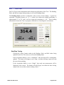
6.6
Test Tab
The Test Tab is used to demonstrate and evaluate the performance of the Trax. The Heading,
Pitch, and Roll are output during testing, as well as the Heading Status.
The Heading Status provides an indication of the accuracy of the heading. A green box
represents a heading accuracy of <2°, a yellow box means the heading uncertainty is
approximately 2° to 10°, and a red box means the uncertainty is >10°. These heading
uncertainties assume the Trax was properly calibrated in a clean magnetic environment.
Start/Stop Testing
Clicking the <Start> button results in the Heading, Pitch, and Roll values being
updated on the Test Tab screen, as well as the Heading Status.
If the Acquisition Mode is set to “Continuous”, then the data will be continuously
updated. The button will change to read <Stop>, such that clicking it again will stop
the screen from updating.
If the Acquisition Mode is set to “Single”, then only one measurement will be
displayed on the screen. The button will briefly gray out while the data is being
output to the screen, then return to reading <Start>.
TRAX User Manual r05
Page 28 of 60
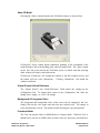
Show 3D Model
Selecting the <Show> button launches the 3D Model window, as shown below.
Clicking the <Start> button begins continuous updating of the orientation of the
rendered model, and of the heading, pitch, and roll output fields. The <Start> button
on the Test Tab screen and on the 3D Model screen are linked such that selecting
either of them will stop or start both screens.
Clicking on <Fullscreen> will expand the window to the full computer screen, and
the button will now read <Windowed>. Clicking <Windowed> will shrink the
window back down.
Output Format & North Reference
The “Output Format” and “North Reference” fields mimic the settings on the
Configuration Tab. To change these, return to the Configuration Tab, make the
change, then <Apply> or <Save> the change.
Background & Foreground Color
The foreground and background colors of the screen can be changed by the user.
Simply click on the color square and select the new desired color. The change in
color automatically is saved. The default is black lettering on a grey background.
Functional Mode
The Trax can operate either in AHRS Mode or Compass Mode. While the Trax is
intended to be used as an AHRS, there are times when it is necessary or beneficial to
PNI Sensor Corporation
TRAX User Manual – March 2012
DOC#1016505 r05
Page 29 of 60
place it in Compass Mode. Specifically, it is necessary to calibrate the Trax in
Compass Mode. (This is handled automatically in Trax Studio, so it is not necessary
for the user to place the Trax in Compass Mode when doing a calibration in Trax
Studio.) Also, it may be beneficial to operate in Compass Mode to conserve battery
life, since in Compass Mode the Trax turns off the gyros, generally uses less CPU
power, and can be placed in Sleep Mode to significantly reduce current consumption.
Truth Method
This field allows the user to have control over the breadth of criteria used to establish
if the local magnetic field conforms to the reference magnetic field criteria. “Auto” is
the default.
Reference Field Reset
Clicking the Reference Field <Reset> button re-establishes the criteria for a clean
magnetic field. After clicking this button the Heading Status box will go green.
Assuming an accurate heading reading is desired, this should be done only when the user
is confident the local magnetic field is free from distortions. For the purpose of
demonstrating the general capabilities of the Trax a distortion-free local magnetic field
may not be required, but the user should realize the heading reading likely will not meet
the accuracy specification.
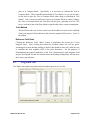
6.7
Log Data Tab
Trax Studio can capture measurement data and then export it to a text file.
TRAX User Manual r05
Page 30 of 60
To acquire data and export it, follow the procedure below:
Select the parameters you wish to log in the window on the left. Use Shift -Click and
Ctrl-Click to select multiple items. In the screen shot above, “Heading”, “Pitch”,
“Roll”, and “Heading Status” were selected. Note that Heading Status can be 0, 1, or
2, corresponding to “green”, “yellow”, or “red”.
Click the <Start> button to start logging. The <Start> button changes to a <Stop>
button after data logging begins.
Click the <Stop> button to stop logging data.
Click the <Export> button to save the data to a file.
Click the <Clear> button to clear the data from the window.
Note that the “Distortion” log indicates if the magnetic field is > ±125 µT for any of the
magnetic sensors. It is only applicable in Compass Mode, and will always read “FALSE” in
AHRS Mode.
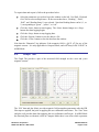
6.8
Graph Tab
The Graph Tab provides a plot of the measured field strength on the x-axis and y-axis
magnetic sensors.
The “Filt” data and plot (blue) provides magnetic field strength measurements after the FIR
filter taps are applied, but prior to applying the user calibration coefficients. The “User” data
and plot (red) provides data after applying the user calibration coefficients. In AHRS Mode
the data and plots are identical, while in Compass Mode there is an offset which represents
PNI Sensor Corporation
TRAX User Manual – March 2012
DOC#1016505 r05
Page 31 of 60
the effect of the calibration coefficients. The Graph Tab normally would be used in Compass
Mode because of this. The graph can be used to visually see hard and soft iron effects within
the environment measured by the Trax, as well as corrected output after a user calibration has
been performed.
The data can be saved to a .txt log file by clicking <Export>. To clear the data, select
<Clear>. To clear both the data and the plot, select <Apply>.
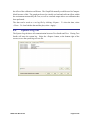
6.9
System Log Tab
The System Log tab shows all communication between Trax Studio and Trax. Closing Trax
Studio will erase the system log. Select the <Export> button, at the bottom right of the
screen, to save the system log to a text file.
TRAX User Manual r05
Page 32 of 60
7 Operation with PNI Binary Protocol
The Trax utilizes PNI’s binary protocol that is transmitted over either a USB virtual
communication port or an RS232 UART. Communication parameters should be set as follows:
Table 7-1: Communication Port Configuration
Parameter
Value
Number of Data Bits
Start Bits
Stop Bits
Parity
8
1
1
none
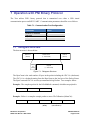
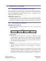
7.1 Datagram Structure
The data structure is shown below:
ByteCount
(UInt16)
Packet Frame
(1 - 4092 UInt8)
Frame
ID
(UInt8)
CRC-16
(UInt16)
Payload
(1 - 4091 UInt8)
Figure 7-1: Datagram Structure
The ByteCount is the total number of bytes in the packet including the CRC-16 (checksum).
The CRC-16 is calculated starting from the ByteCount to the last byte of the Packet Frame.
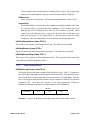
The ByteCount and CRC-16 are always transmitted in big Endian. Two examples follow.
Example: The complete packet for the kGetModInfo command, which has no payload is:
00 05
01
EF D4
ByteCount
Frame ID
Checksum
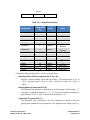
Example: Below is a complete sample packet to start a 2D Calibration (kStartCal):
00 09
0A
00 00
00 14
5C F9
ByteCount
Frame ID
CalOption
(MSBs)
CalOption
(2D Calibration)
Checksum
PNI Sensor Corporation
TRAX User Manual – March 2012
DOC#1016505 r05
Page 33 of 60
7.2 Parameter Formats
Note: Floating-point based parameters conform to ANSI/IEEE Std 754-1985. Please refer to the
Standard for more information. PNI also recommends the user refer to the compiler’s instructions to
understand how the compiler implements floating-point format.
64-Bit Floating Point (Float64)
Below is the 64-bit float format in big Endian. In little Endian, the bytes are in
reverse order in 4 byte groups. (eg. big Endian: ABCD EFGH; little Endian:
DCBA HGFE).
63 62
52 51
S
0
Exponent
Mantissa
The value (v) is determined as:
v = (-1)S * 2(Exponent-1023) * 1.Mantissa, if and only if 0 < Exponent < 2047
32-Bit Floating Point (Float32)
Shown below is the 32-bit float format in big Endian. In little Endian format, the 4
bytes are in reverse order (LSB first).
3130
23 22
S
0
Exponent
Mantissa
The value (v) is determined as:
v = (-1)S * 2(Exponent-127) * 1.Mantissa, if and only if 0 < Exponent < 255
Signed 32-Bit Integer (SInt32)
SInt32-based parameters are signed 32-bit numbers (2’s compliment).
represents the sign of the value, where 0=positive and 1=negative.
31
24 23
16 15
8 7
msb
Bit 31
0
lsb
Big Endian
7
0 15
8 23
lsb
16 31
24
msb
Little Endian
TRAX User Manual r05
Page 34 of 60
Signed 16-Bit Integer (SInt16)
SInt16-based parameters are signed 16-bit numbers (2’s compliment).
represents the sign of the value, where 0=positive and 1=negative.
15
8 7
msb
0
7
lsb
0 15
8
lsb
Big Endian
Bit 15
msb
Little Endian
Signed 8-Bit Integer (SInt8)
UInt8-based parameters are unsigned 8-bit numbers. Bit 7 represents the sign of the
value, where 0=positive and 1=negative.
7
0
byte
Unsigned 32-Bit Integer (UInt32)
UInt32-based parameters are unsigned 32-bit numbers.
31
24 23
16 15
8 7
msb
0
lsb
Big Endian
7
0 15
8 23
16 31
lsb
24
msb
Little Endian
Unsigned 16-Bit Integer (UInt16)
UInt16-based parameters are unsigned 16-bit numbers.
15
8 7
msb
0
lsb
7
0 15
lsb
Big Endian
8
msb
Little Endian
Unsigned 8-Bit Integer (UInt8)
UInt8-based parameters are unsigned 8-bit numbers.
PNI Sensor Corporation
TRAX User Manual – March 2012
DOC#1016505 r05
Page 35 of 60
7
0
byte
Boolean
Boolean is a 1-byte parameter that MUST have the value 0=FALSE or 1=TRUE.
7
0
byte
7.3 Commands Overview
Table 7-2 provides a summary of the basic commands available with the Trax. These
commands are discussed in the following subsections.
Table 7-2: Trax Binary Command Set
Frame
Command
IDd
Set Up
1
2
6
19
7
8
kGetModInfo
kGetModInfoResp
kSetConfig
kSetConfigDone
kGetConfig
kGetConfigResp
119
kSetMagTruthMethod
120
121
kGetMagTruthMethod
kGetMagTruthMethodResp
9
kSave
16
kSaveDone
Operation
110
kSetResetRef
24
kSetAcqParams
26
kSetAcqParamsDone
25
kGetAcqParams
27
kGetAcqParamsResp
3
kSetDataComponents
4
kGetData
5
kGetDataResp
21
kStartContinuousMode
22
kStopContinuousMode
TRAX User Manual r05
Description
Queries the device’s type and firmware revision.
Response to kGetModInfo
Sets internal configurations in Trax
Response to kSetConfig
Queries Trax for the current internal configuration
Response to kGetConfig
Sets if dip angle & radius establish mag truth
(standard) or additional criteria (tight).
Queries for standard or tight truth method.
Response to kGetMagTruthMethod
Saves the current internal configuration and any new
user calibration coefficients to non-volatile memory.
Response to kSave
Establishes criteria for the reference magnetic field.
Sets the sensor acquisition parameters
Response to kSetAcqParams
Queries for the sensor acquisition parameters
Response to kGetAcqParams
Sets the data components to be output.
Queries the Trax for data
Response to kGetData
Commands the Trax to output data at a fixed interval
Stops data output when in Continuous Mode
Page 36 of 60
Calibration
10
kStartCal
11
kStopCal
31
kTakeUserCalSample
17
kUserCalSampleCount
18
kUserCalScore
29
kSetFactoryMagCoeff
30
kSetFactoryMagCoeffDone
36
kSetFactoryIAccelCoeff
37
kSetFactoryAccelCoeffDone
Compass Mode
79
kSetFunctionalMode
80
kGetFunctionalMode
81
kGetFunctionalModeResp
12
kSetFIRFilters
20
kSetFIRFiltersDone
13
kGetFIRFilters
14
kGetFIRFiltersResp
15
28
23
kPowerDown
kPowerDownDone
kPowerUpDone
Commands the Trax to start user calibration
Commands the Trax to stop user calibration
Commands the Trax to take a sample during user
calibration
Sent from the Trax after taking a calibration sample
point
Contains the calibration score
Resets magnetometer calibration coefficients to
original factory-established values
Response to kSetFactoryMagCoeff
Resets accelerometer calibration coefficients to
original factory-established values
Respond to kSetFactoryAccelCoeff
Puts Trax in Compass Mode or AHRS Mode
Queries for Compass Mode or AHRS Mode
Response to kGetFunctionalMode
Sets the FIR filter settings for the magnetometer &
accelerometer sensors.
Response to kSetFIRFilters
Queries for the FIR filter settings for the magnetometer
& accelerometer sensors.
Contains the FIR filter settings for the magnetometer &
accelerometer sensors.
Powers down the module
Response to kPowerDown
Confirms the Trax has received a signal to power up
7.4 Set-Up Commands
7.4.1
Module Information
kGetModInfo (frame ID 1d)
This frame queries the device's type and firmware revision number. The frame has no
payload.
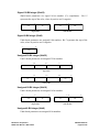
kGetModInfoResp (frame ID 2d)
The response to kGetModInfo is given below. The payload contains the device type
identifier followed by the firmware revision number.
Payload
Type
Revision
UInt32
UInt32
PNI Sensor Corporation
TRAX User Manual – March 2012
DOC#1016505 r05
Page 37 of 60
Note that the Type and Revision can be decoded from the binary format to character
format using the ASCII standard. For example, the hex string “00 0D 02 54 52 41 58
31 32 30 38 C7 87” can be decoded to read “Trax 1208”.
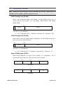
7.4.2
Module Configuration
kSetConfig (frame ID 6d)
This frame sets internal configurations in the Trax. The first byte of the payload is
the configuration ID followed by a format-specific value. These configurations can
only be set one at time. To save these in non-volatile memory, the kSave command
must be issued.
Payload
Config ID
Value
UInt8
ID Specific
Example: To configure the declination, the payload would look like:
Payload
1
10.0
Declination ID
Declination
Angle (Float32)
TRAX User Manual r05
Page 38 of 60
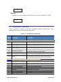
Table 7-3: Configuration Identifiers
Settings
Config. IDd Format
kDeclination
kTrueNorth
kBigEndian
1
2
6
Float32
Boolean
Boolean
kMountingRef
10
UInt8
kUserCalNumPoints
kUserCalAutoSampling
12
13
UInt32
Boolean
kBaudRate
14
UInt8
kMilOut
kHPRDuringCal
kMagCoeffCopySet
kAccelCoeffCopySet
15
16
18
19
Boolean
Boolean
UInt32
UInt32
Values / Range
Default
-180˚ to +180˚
True or False
True or False
1 = STD 0°
2 = X UP 0°
3 = Y UP 0°
4 = STD 90°
5 = STD 180°
6 = STD 270°
7 = Z DOWN 0°
8 = X UP 90°
9 = X UP 180°
10 = X UP 270°
11 = Y UP 90°
12 = Y UP 180°
13 = Y UP 270°
14 = Z DOWN 90°
15 = Z DOWN 180°
16 = Z DOWN 270°
4 – 18
True or False
4 – 2400
5 – 3600
6 – 4800
7 – 7200
8 – 9600
9 – 14400
10 – 19200
11 – 28800
12 – 38400
13 – 57600
14 - 115200
True or False
True or False
0-7
0-7
0
False
True
1
12
True
12
False
True
0
0
Configuration parameters and settings for kSetConfig:
kDeclination (Config. ID 1d)
This sets the declination angle to determine True North heading. Positive
declination is easterly declination and negative is westerly declination. This is not
applied unless kTrueNorth is set to TRUE.
PNI Sensor Corporation
TRAX User Manual – March 2012
DOC#1016505 r05
Page 39 of 60
kTrueNorth (Config. ID 2d)
Flag to set compass heading output to true north heading by adding the
declination angle to the magnetic north heading.
kBigEndian (Config. ID 6d)
Sets the Endianness of packets. TRUE is Big Endian. FALSE is Little Endian.
kMountingRef (Config. ID 10d)
This sets the reference orientation for the Trax. Please refer to Figure 4-2 for
additional information.
kUserCalNumPoints (Config. ID 12d)
The user must select the number of points to take during a calibration. The
number of sample points must be within the listed “Allowable Range” or the Trax
may not work properly. Calibration generally is not as good if less than the
“Minimum Recommended” is selected, but may be acceptable.
Table 7-4: Sample Points
Number of Samples
Calibration Mode
Full Range Calibration
Limited Tilt Calibration
2D Calibration
Hard Iron Only
Accelerometer
Allowable
Range
Recommended
Pattern
10 to 18
10 to 18
10 to 18
4 to 18
18
12
12
12
6
18
kUserCalAutoSampling (Config. ID 13d)
This flag is used during user calibration. If set to TRUE, the Trax automatically
takes calibration sample points once the minimum change and stability
requirements are met. If set to FALSE, the device waits for kTakeUserCalSample
to take a sample with the condition that a magnetic field vector component delta is
greater than 5 µT from the last sample point. If the user wants to have maximum
control over when the calibration sample point are taken then this flag should be
set to FALSE.
kBaudRate (Config. ID 14d)
Baud rate index value.
changing the baud rate.
A power-down, power-up cycle is required when
kMilOut (Config. ID 15d)
Sets the output units as mils (TRUE) or degrees (FALSE). The default is FALSE.
TRAX User Manual r05
Page 40 of 60
kHPRDuringCal (Config. ID 16d)
This flag sets whether or not heading, pitch, and roll data are output
simultaneously while the Trax is being calibrated. The default is TRUE, such that
heading, pitch, and roll are output during calibration. FALSE disables
simultaneous output.
kMagCoeffCopySet (Config. ID 18d)
This command provides the flexibility to store up to eight (8) sets of
magnetometer calibration coefficients in the Trax. The default is set number 0.
To store a set of coefficients, first establish the set number (number 0 to 7) using
kMagCoeffCopySet, then perform the magnetometer calibration. The coefficient
values will be stored in the defined set number. This feature is useful if the
compass will be placed in multiple locations that have different local magnetic
field properties.
kAccelCoeffCopySet (Config. ID 19d)
This command provides the flexibility to store up to eight (8) sets of
accelerometer calibration coefficients in the Trax. The default is set number 0.
To store a set of coefficients, first establish the set number (number 0 to 7) using
kAccelCoeffCopySet, then perform the accelerometer calibration. The coefficient
values will be stored in the defined set number.
kSetConfigDone (frame ID 19 d)
This frame is the response to kSetConfig frame. The frame has no payload.
kGetConfig (frame ID 7d)
This frame queries the Trax for the current internal configuration value. The payload
contains the configuration ID requested.
Payload
Config ID
UInt8
kGetConfigResp (frame ID 8d)
The response to kGetConfig is given below. The payload contains the configuration
ID and value.
Payload
Config ID
Value
UInt8
ID Specific
Example: If a request to get the set declination angle, the payload would look like:
PNI Sensor Corporation
TRAX User Manual – March 2012
DOC#1016505 r05
Page 41 of 60
Payload
1
10.0
Declination ID
Declination
Angle (Float32)
kSetMagTruthMethod (frame ID 119 d)
This frame allows the user to have control over the breadth of criteria used to
establish if the local magnetic field conforms to the reference magnetic field criteria.
The “AutoMerge” criteria is the default. The payload is defined below.
Payload
MagTruthMethod
UInt8
MagTruthMethod Payload Value:
“1”: Standard
“2”: Tight
“3”: AutoMerge
kGetMagTruthMethod (frame ID 120 d)
This frame queries the setting of the Mag Truth Method. It has no payload.
kGetMagTruthMethodResp (frame ID 121 d)
This frame is the response of kGetMagTruthMethod and the payload is the same as
for kSetMagTruthMethod.
7.4.3
Saving Settings
kSave (frame ID 9d)
This frame commands the Trax to save internal configurations and user calibration to
non-volatile memory. Internal configurations and user calibration are restored on
power up. The frame has no payload. This is the ONLY command that causes the
device to save information to non-volatile memory.
kSaveDone (frame ID 16 d)
This frame is the response to kSave frame. The payload contains a UInt16 error code:
0 indicates no error; 1 indicates an error when attempting to save data to memory.
Payload
Error Code
UInt16
TRAX User Manual r05
Page 42 of 60
7.5 Measurement Commands
7.5.1
Setting the Reference Magnetic Field Criteria
Prior to operating the Trax in AHRS mode it is necessary to establish the criteria for a
known distortion-free local field. This should be done with the Trax installed in the host
system, as the distortion presented by the host system is constant and will be
compensated for by the Trax algorithms.
kSetResetRef (frame ID 110 d)
This frame re-aligns the Trax 9-axis heading to the 6-axis (mag and accel) heading
and establishes the criteria for the reference magnetic field. The frame should be sent
when the user is confident the local magnetic field is not distorted. It has no payload.
7.5.2
Data Acquisition Parameters
kSetAcqParams (frame ID 24 d)
This frame sets the sensor acquisition parameters in the Trax. The payload should
contain the following:
Payload
AcquisitionMode
FlushFilter
UInt8
UInt8
PNIReserved
Float32
SampleDelay
Float32
AcquisitionMode:
This flag sets whether output will be presented in Continuous or Polled
Acquisition Mode. Continuous Mode is TRUE and is the default. Polled Mode
should be selected when the host system will poll the Trax for each data set.
Continuous Mode should be selected if the user will have the Trax output data to
the host system at a relatively fixed rate.
FlushFilter:
This is only relevant in Compass Mode. Setting this flag to TRUE results in the
FIR filter being flushed (cleared) after every measurement. The default is
FALSE.
Flushing the filter clears all tap values, thus purging old data. This can be useful
if a significant change in heading has occurred since the last reading, as the old
heading data would be in the filter. Once the taps are cleared, it is necessary to
fully repopulate the filter before data is output. For example, if 32 FIR taps is set,
PNI Sensor Corporation
TRAX User Manual – March 2012
DOC#1016505 r05
Page 43 of 60
32 new samples must be taken before a reading will be output. The length of the
delay before outputting data is directly correlated to the number of FIR taps.
PNIReserved:
These 4 bytes serve no function. PNI recommends populating the bytes with 0.
SampleDelay:
The SampleDelay is relevant when the Continuous Acquisition Mode is selected.
It is the time delay, in seconds, between completion of Trax sending one set of
data and the start of sending the next data set. The default is 0 seconds, which
means Trax will send new data as soon as the previous data set has been sent.
Note that the inverse of the SampleDelay is somewhat greater than the actual
sample rate, since the SampleDelay does not include actual acquisition time.
kSetAcqParamsDone (frame ID 26 d)
This frame is the response to kSetAcqParams frame. The frame has no payload.
kGetAcqParams (frame ID 25 d)
This frame queries the unit for acquisition parameters. The frame has no payload.
kGetAcqParamsResp (frame ID 27 d)
This frame is the response to kGetAcqParams frame. The payload should contain the
same payload as the kSetAcqParams frame.
7.5.3
Data Components
kSetDataComponents (frame ID 3d)
This frame defines what data is output when kGetData is sent. Table 7-5 summarizes
the various data components and more detail follows this table. Note that this is not a
query for the device's model type and software revision (see kGetModInfo). The first
byte of the payload indicates the number of data components followed by the data
component IDs. Note that the sequence of the data components defined by
kSetDataComponents will match the output sequence of kGetDataResp.
Payload
ID Count
ID 1
ID 2
ID 3
UInt8
UInt8
UInt8
UInt8
……….
Example: To query for heading and heading status, the payload should contain:
TRAX User Manual r05
Page 44 of 60
Payload
2
5
79
ID Count
Heading ID
Pitch ID
Table 7-5: Component Identifiers
Component
Component
Format
IDd
kHeading
kPitch
kRoll
kHeadingStatus
kQuaternion
kTemperature
5
24
25
79
77
7
Float32
Float32
Float32
UInt8
4x Float32
Float32
kDistortion
8
Boolean
kCalStatus
9
Boolean
kAccelX
kAccelY
kAccelZ
kMagX
kMagY
kMagZ
kGyroX
kGyroY
kGyroZ
21
22
23
27
28
29
74
75
76
Float32
Float32
Float32
Float32
Float32
Float32
Float32
Float32
Float32
Units
degrees
degrees
degrees
value
quaternion
˚ Celsius
True or False
(Default)
True or False
(Default)
G
G
G
T
T
T
radians/sec
radians/sec
radians/sec
Component types are listed below. All are read-only values.
kHeading, kPitch, kRoll (Component IDs 5d, 24d, 25d)
Provides compass heading, pitch and roll outputs. The heading range is 0.0˚ to
+359.9˚, the pitch range is -90.0˚ to +90.0˚, and the roll range is to -180.0˚ to
+180.0˚.
kHeadingStatus (Component IDs 79d)
The heading status provides an indication of the uncertainty of the heading. “1”
represents a heading uncertainty of <2°, “2” means the heading uncertainty is
approximately 2° to 10°, and “3” means the uncertainty is >10°.
Quaternion (Component ID 77d)
The quaternion values generated by the Trax algorithm are output in one data
package that contains the four quaternions. The quaternions are output as Q0, Q1,
PNI Sensor Corporation
TRAX User Manual – March 2012
DOC#1016505 r05
Page 45 of 60
Q2, and Q3, where Q3 is the scalar quaternion. When in AHRS Mode, heading,
pitch, and roll are subsequently calculated from these quaternions.
kTemperature (Component ID 7d)
This value is provided by the device’s internal temperature sensor. Its value is in
degrees Celsius and has an accuracy of ±3° C.
kDistortion (Component ID 8d)
This flag indicates at least one magnetometer axis reading is beyond ±125 µT. It
is only applicable in Compass Mode, and will always read “FALSE” in AHRS
Mode.
kCalStatus (Component ID 9d)
This flag indicates the user calibration status. False means it is not user calibrated
and this is the default value.
kAccelX, kAccelY & kAccelZ (Component IDs 21d, 22d, 23d)
These values represent the accelerometer sensor data for the x, y, and z axis,
respectively. The values are normalized to g (Earth’s gravitational force).
kMagX, kMagY & kMagZ (Component IDs 27d, 28d, 29d)
These values represent the magnetic sensor data for the x, y, and z axis,
respectively. The values are given in µT.
kGyroX, kGyroY, kGyroZ (Component IDs 74d, 75d, 76d)
These values represent the gyroscope sensor data for rotation around the x, y, and
z axis, respectively. The values are in radians per second.
7.5.4
Making a Measurement
kGetData (frame ID 4d)
If the Trax is configured to operate in Polled Acquisition Mode (see kSetAcqParams),
then this frame requests a single measurement data set. The frame has no payload.
kStartContinuousMode (frame ID 21 d)
If the Trax is configured to operate in Continuous Acquisition Mode (see
kSetAcqParams), then this frame initiates the outputting of data at a relatively fixed
data rate, where the data rate is established by the SampleDelay parameter. The
frame has no payload.
kStopContinuousMode (frame ID 22 d)
This frame commands the Trax to stop data output when in Continuous Acquisition
Mode. The frame has no payload.
TRAX User Manual r05
Page 46 of 60
kGetDataResp (frame ID 5d)
The response to kGetData and kStartContinuousMode is kGetDataResp. The specific
data fields that will be output (ID 1, Value ID 1, etc.) should have been previously
established by the kSetDataComponents command frame.
Payload
ID Count
UInt8
ID 1
Value ID 1
ID 2
Value ID 2
ID 3
Value ID 3
UInt8
ID Specific
UInt8
ID Specific
UInt8
ID Specific
If heading and heading status are set to be output per the
kSetDataComponents command, the payload would look like:
Example:
Payload
2
5
359.9
79
ID Count
Heading ID
Heading
(Float32)
Heading
Status ID
1
Heading
Status (UInt8)
7.6 Calibration Commands
7.6.1
User Calibration Commands
First, note that in order to perform a user calibration, it is necessary to place the Trax in
Compass Mode, as discussed in Section 7.7. Note that Trax allows for a maximum of 12
calibration points.
kStartCal (frame ID 10d)
This frame commands the Trax to start user calibration with the current sensor
acquisition parameters, internal configurations and FIR filter settings.
Payload
CalOption
UInt32
CalOption Payload Value:
“10d” or “0Ah”: Full Range Calibration (default)
“20d” or “14h”: 2D Calibration
“30d” or “1Eh”: Hard Iron Only Calibration
“40d” or “28h”: Limited Tilt Range Calibration
“100d” or “64h”: Accelerometer Calibration
Note: The payload needs to be 32 bit (4 byte). If no payload is entered or if less than 4 bytes
are entered, the unit will default to the previous calibration method.
PNI Sensor Corporation
TRAX User Manual – March 2012
DOC#1016505 r05
Page 47 of 60
The CalOption values are given below, along with basic descriptions of the options.
Full Range Calibration
Recommended calibration method when >45° of tilt is possible. Can be used for
between 20° and 45° of tilt, but accuracy will not be as good
2D Calibration
Recommended when the available tilt range is limited to ≤5°. Can be used for 5°
to 10° of tilt, but accuracy will not be as good.
Hard Iron Only Calibration
Recalibrates the hard iron offset for a prior calibration. If the local field hard iron
distortion has changed, this calibration can bring the Trax back into specification.
Limited Tilt Range Calibration
Recommended calibration method when >5° of tilt calibration is available, but tilt
is restricted to <45°. (i.e. full range calibration is not possible.)
Accelerometer Calibration
Select this when an accelerometer calibration will be performed.
Below is a complete sample packet to start a 2D Calibration (kStartCal):
00 09
0A
00 00
00 14
5C F9
ByteCount
Frame ID
CalOption
(MSBs)
CalOption
(2D Calibration)
Checksum
Heading, pitch and roll information is output via the kGetDataResp frame during the
calibration process. This feature provides guidance during the calibration regarding
calibration sample point coverage. During calibration, in the kGetDataResp frame,
the number of data components is set to be 3 and then followed by the data
component ID-value pairs. The sequence of the component IDs are kHeading, kPitch
and kRoll.
kTakeUserCalSample (frame ID 31 d)
This frame commands the Trax to take a sample during user calibration. The frame
has no payload.
TRAX User Manual r05
Page 48 of 60
kUserCalSampleCount (frame ID 17 d)
This frame is sent from the Trax after taking a calibration sample point. The payload
contains the sample count with the range of 1 to 18.
Payload
SampleCount#
UInt32
kStopCal (frame ID 11d)
This command aborts the calibration process.
retained.
7.6.2
The prior calibration results are
Performing a User calibration
The steps below provide an example of the steps to perform a user calibration.
Using the kSetParam command, set the number of tap filters to 0.
Using the kSetConfig command, set kUserCalAutoSampling. “False” is generally
recommended, but “True” may be more convenient.
Using the kSetConfig command, set kCoeffCopySet (magnetometer calibration)
and/or kAccelCoeffCopySet (accelerometer calibration). These fields allow the
user to save multiple sets of calibration coefficients. “0” is the default.
Using the kSetConfig command again, set kUserCalNumPoints to the appropriate
number of calibration points.
Initiate a calibration using the kStartCal command. Note that this command
requires indentifying the type of calibration procedure (i.e. Full Range, 2D, etc.).
Follow the appropriate calibration procedure, as discussed in Section 5. If
kUserCalAutoSampling was set to “False”, then send a kTakeUserCalSample
command when ready to take a calibration point. If kUserCalAutoSampling was
set to “True”, then look for kUserCalSampCount to confirm when a calibration
point has been taken. During the calibration process, heading, pitch, and roll
information will be output from the Trax, and this can be monitored using
kDataResp.
When the final calibration point is taken, the device will present the calibration
score using kUserCalScore.
If the calibration is acceptable (see Section 7.6.2), save the calibration coefficients
using kSave.
PNI Sensor Corporation
TRAX User Manual – March 2012
DOC#1016505 r05
Page 49 of 60
7.6.3
Calibration Score
kUserCalScore (frame ID 18 d)
The calibration score is automatically sent upon taking the final calibration point.
The payload is defined below, and the various payload components are discussed
after this.
Payload
MagCalScore
Bytes 5-8
Float32
Float32
AccelCalScore
Float32
DistributionError
TiltError
TiltRange
Float32
Float32
Float32
MagCalScore:
Represents the over-riding indicator of the quality of the magnetometer
calibration. Acceptable scores will be ≤1 for full range calibration, ≤2 for other
methods. Note that it is possible to get acceptable scores for DistributionError
and TiltError and still have a rather high MagCalScore value. The most likely
reason for this is the Trax is close to a source of local magnetic distortion that is
not fixed with respect to the device.
Bytes 5-8:
Reserved for PNI use.
AccelCalScore:
Represents the over-riding indicator of the quality of the accelerometer
calibration. An acceptable score is ≤1.
DistributionError:
Indicates if the distribution of sample points is good, with an emphasis on the
heading distribution. The score should be 0. Significant clumping or a lack of
sample points in a particular section can result in a poor score.
TiltError:
Indicates if the Trax experienced sufficient tilt during the calibration, taking into
account the calibration method. The score should be 0.
TiltRange:
This reports the larger of either half the full pitch range or half the full roll range
of sample points. For example, if the device is pitched +10° to -20º, and rolled
+25º to -15º, the TiltRange value would be 20º (as derived from [+25º {-15º}]/2). For Full Range Calibration and Hard Iron Only Calibration, this
should be ≥45°. For 2D Calibration, ideally this should be ≈2°. For Limited Tilt
Range Calibration the value should be as large a possible given the user’s
constraints.
TRAX User Manual r05
Page 50 of 60
7.6.4
Factory Calibration
kSetFactoryMagCoeff (frame ID 29 d)
This frame clears the magnetometer calibration coefficients and loads the original
factory-generated coefficients. The frame has no payload. This frame must be
followed by the kSave frame to save the change in non-volatile memory.
kSetFactoryMagCoeffDone (frame ID 30 d)
This frame is the response to kFactoryMagCoeff frame. The frame has no payload.
kSetFactoryAccelCoeff (frame ID 36 d)
This frame clears the accelerometer calibration coefficients and loads the original
factory-generated coefficients. The frame has no payload. This frame must be
followed by the kSave frame to save the change in non-volatile memory.
kSetFactoryAccelCoeffDone (frame ID 37 d)
This frame is the response to kFactoryAccelCoeff frame. The frame has no payload.
7.7 Compass Mode Commands
The Trax normally operates in AHRS Mode, which uses a proprietary Kalman algorithm to
fuse the inputs of its 3-axis gyroscope, 3-axis accelerometer, and 3-axis magnetometer.
However, the user can place the Trax in Compass Mode, wherein it only uses the inputs from
the accelerometer and magnetometer to establish heading, pitch, and roll. In this case the
Trax operates very similarly to PNI’s TCM electronic compass.
There are a couple of reasons it may be desirable to place the Trax in Compass Mode. As
previously mentioned, it is necessary to place the Trax in Compass Mode to perform a
calibration. Additionally, if a static measurement is to be made in a known clean local
magnetic field, then a somewhat higher level of accuracy is achievable in Compass Mode.
Also, by placing the Trax in Compass Mode it can subsequently be placed into Sleep Mode
which will significantly reduce power consumption when not taking measurements.
7.7.1
Switching Functional Mode
kSetFunctionalMode (frame ID 79 d)
This frame establishes whether the Trax operates in AHRS Mode or Compass Mode.
The frame has a one byte payload. The payload byte is “0” to operate in Compass
Mode and “1” to operate in AHRS Mode. The default is “1”.
PNI Sensor Corporation
TRAX User Manual – March 2012
DOC#1016505 r05
Page 51 of 60
Payload
FunctionalMode
UInt8
FunctionalMode Payload Value:
“0”: Compass Mode
“1”: AHRS Mode (default)
Sending the kSave command after changing the mode will save the new setting in
non-volatile memory.
kGetFunctionalMode (frame ID 80 d)
This frame queries the Trax functional mode. The frame has no payload.
kGetFunctionalModeResp (frame ID 81 d)
This is the response of kGetFunctionalMode, and it has the same payload definition
as kSetFunctionalMode.
7.7.2
FIR Filters
When operating in Compass Mode, the Trax incorporates a finite impulse response (FIR)
filter to provide a more stable heading reading. The number of taps (or samples)
represents the amount of filtering to be performed. The number of taps directly affects
the time for the initial sample reading, as all the taps must be populated before data is
output. The FIR filter settings have no affect when operating in AHRS Mode.
The Trax can be configured to clear, or flush, the filters after each measurement, as
discussed in Section 7.5.2. Flushing the filter clears all tap values, thus purging old data.
This can be useful if a significant change in heading has occurred since the last reading,
as the old heading data would be in the filter. Once the taps are cleared, it is necessary to
fully repopulate the filter before data is output. For example, if 32 FIR taps is set, 32 new
samples must be taken before a reading will be output. The length of the delay before
outputting data is directly correlated to the number of FIR taps.
kSetFIRFilters (frame ID 12d)
The payload for kSetFIRFilters is given below.
Payload
Byte 1
Byte 2
Count N
Value 1
Value 2
Value 3
Value N
UInt8
UInt8
UInt8
ID Specific
ID Specific
ID Specific
ID Specific
Byte 1 should be set to 3 and Byte 2 should be set to 1. The third payload byte
indicates the number of FIR taps to use, which can be 0 (no filtering), 4, 8, 16, or 32.
This is followed by the tap values (0 to 32 total Values can be in the payload), with
each Value being a Float64, and suggested values given in Table 7-6.
TRAX User Manual r05
Page 52 of 60
Table 7-6: Recommended FIR Filter Tap Values
Count 4-Tap Filter
8-Tap Filter
16-Tap Filter
32-Tap Filter
1
04.6708657655334e-2
01.9875512449729e-2
07.9724971069144e-3
01.4823725958818e-3
2
04.5329134234467e-1
06.4500864832660e-2
01.2710056429342e-2
02.0737124095482e-3
3
04.5329134234467e-1
01.6637325898141e-1
02.5971390034516e-2
03.2757326624196e-3
4
04.6708657655334e-2
02.4925036373620e-1
04.6451949792704e-2
05.3097803863757e-3
5
02.4925036373620e-1
07.1024151197772e-2
08.3414139286254e-3
6
01.6637325898141e-1
09.5354386848804e-2
01.2456836057785e-2
7
06.4500864832660e-2
01.1484431942626e-1
01.7646051430536e-2
8
01.9875512449729e-2
01.2567124916369e-1
02.3794805168613e-2
9
01.2567124916369e-1
03.0686505921968e-2
10
01.1484431942626e-1
03.8014333463472e-2
11
09.5354386848804e-2
04.5402682509802e-2
12
07.1024151197772e-2
05.2436112653103e-2
13
04.6451949792704e-2
05.8693165018301e-2
14
02.5971390034516e-2
06.3781858267530e-2
15
01.2710056429342e-2
06.7373451424187e-2
16
07.9724971069144e-3
06.9231186101853e-2
17
06.9231186101853e-2
18
06.7373451424187e-2
19
06.3781858267530e-2
20
05.8693165018301e-2
21
05.2436112653103e-2
22
04.5402682509802e-2
23
03.8014333463472e-2
24
03.0686505921968e-2
25
02.3794805168613e-2
26
01.7646051430536e-2
27
01.2456836057785e-2
28
08.3414139286254e-3
29
05.3097803863757e-3
30
03.2757326624196e-3
31
02.0737124095482e-3
32
01.4823725958818e-3
PNI Sensor Corporation
TRAX User Manual – March 2012
DOC#1016505 r05
Page 53 of 60
kSetFIRFiltersDone (frame ID 20 d)
This frame is the response to kSetFIRFilters. The frame has no payload.
kGetFIRFilters (frame ID 13d)
This frame queries the FIR filter settings for the sensors. Byte 1 should be set to 3
and Byte 2 should be set to 1.
Payload
Byte 1
Byte 2
UInt8
UInt8
kGetFIRFiltersResp (frame ID 14d)
This is the response to kGetFIRFilters and it has the same payload definition as
kSetFIRFilters.
7.7.3
Power Down/Up
For certain applications it is desirable to conserve battery power. To maintain accurate
heading readings in AHRS Mode generally requires continual sensor updates to the
Kalman algorithm. However, this is not the case in Compass Mode wherein readings
may be taken only when heading information is desired. Consequently, when in
Compass Mode the Trax may be powered down when heading data is not required.
kPowerDown (frame ID 15d)
This frame is used to power-down the module. The frame has no payload. The
command will power down all peripherals including the sensors, microprocessor, and
RS-232 driver. However, the driver chip has a feature to keep the Rx line enabled.
The Trax will power up when it receives any signal on the native UART Rx line.
kPowerDownDone (frame ID 28d)
This frame confirms the Trax received a command to power down. The frame has no
payload.
kPowerUpDone (frame ID 23d)
This frame confirms the Trax received a command to power up. (The Trax will
power up when it receives any signal on the native UART Rx line.) The frame has no
payload.
TRAX User Manual r05
Page 54 of 60