1
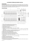
24CH DMX CONTROLLER
Item No: CK103
CK-103
USER MANUAL
www.cklight.com.cn
©Copyright
24 CH DMX CONTROLLER USER
USER’’S
MANUAL
General Description
This digital DMX light controller can control 24 light channels and
gives total dimmer control over all 24 outputs. It features 48 easily
programmable memories with a storage capacity for 99 different light
effect scenes per memory. It can be set on automatic control or on
music control via the built-in microphone or via an external audio
signal. The speed and fade time for the running light are also
” for the
selectable. The digital DMX-512 control uses “addresses
addresses”
individual control of the connected light units. These outgoing
addresses are pre-set to the numbers 1 to 24.
Controls and Functions
1) Indicator LEDs for the setting of the slider controls from section A.
2) 12 slider controls adjusting the light intensity of channel 1 to 12.
3)
4)
5)
6)
7)
Push-buttons with ‘flash
flash’’ function for channel 1 to 12.
Indicator LEDs for the setting of the slider controls from section B.
LED indicating the active scenes.
Slider controls for the channels 13 to 24.
Flash buttons 13 to 24 allowing to completely switch on shortly
one channel.
8) MASTER A slider control for the setting of the light intensity on
channel 1 to 12 (section A) or on all 24 channels simultaneously.
9) ‘BLIND
BLIND’’ button to exclude one or more channels simultaneously
from a scene pattern. The light intensity of that channel will then
be determined by the appropriate slider control of the channel.
10) MASTER B slider control setting the light intensity of channels 13
to 24.
11) ‘HOME
HOME’’ button to switch off the ‘Blind
Blind’’ function.
12) Slider control for the setting of the fade time between the scenes.
13) TAP SYNC button to synchronize the STEP rhythm with the music.
14) SPEED slider control to set the STEP speed of the running light
patterns.
15) ‘FULL-ON
FULL-ON’’ button to switch all outputs to 100% intensity.
16) AUDIO LEVEL slider control to set the sensitivity of the built-in
microphone or of the audio signal that is fed into the LINE-IN input.
17) BLACK OUT button switches all outputs to zero. The yellow LED is
flashing.
18) STEP button to activate the following scene.
19) AUDIO button switches the music control on.
20) HOLD button stops the execution of all pattern steps.
21) PARK button to select between individual or mixed running light
patterns.
22) REC EXIT button has two functions: a) in programming mode you
can choose between ADD or KILL function of a scene, and b) leave
the programming mode.
23) RECORD button to store the scenes in programming mode.
24) PAGE/REC CLEAR button to select a memory page from 1 to 4.
25) MODE SELECT button to choose among automatic running light
(red) or single (yellow) or double pre-set (green).
26) DARK button to switch all outputs to zero regardless of the FULLON button.
27) ALL REV/EDIT button: push to invert the running direction of all
scenes.
28) % OR 0-255 button changes the indication on the display.
29) DELETE/REV ONE button inverts the running direction of a
determined scene.
30) UP/CHASE REV button to invert the running direction of the
current running light program.
31) DOWN/BEAT REV. Button inverts the running direction in music
controlled mode.
Connections at the rear panel
On the rear panel are located a number of connectors and a slider
control, i.e.: a small connector for the included power supply (1), a
block of 3 DIN connectors for MIDI (2, 3 and 4), a 3-pin DIN connector
for the DMX signals (5) featuring a push switch for polarity inversion
(6) an RCA connector for an external audio signal (7) and a 6.3 mm
jack for a foot switch (8).
BASIC FUNCTIONS FOR PROGRAMMING
1) Activation of the programming mode:
Keep the RECORD/SHIFT button pushed in and press in sequence the
flash buttons 1, 5, 6 and 8. These buttons are located just below the
slider controls in the upper row PRESET A. Release the
RECORD/SHIFT button. The red programming LED should light up.
2) Exit the programming mode:
Hold the RECORD/SHIFT button down and press simultaneously the
REC/EXIT button. The red programming LED goes off.
3) Erasing all programs (be careful !):
Activate the programming mode as described above in step 1. Hold
the RECORD/SHIFT button down and press in sequence the flash
buttons 1, 3, 2 and 3 in the section PRESET A. Release the
RECORD/SHIFT button. All stored running light scenes are now
erased from the ROM. All LEDs flash to confirm. Press the
RECORD/SHIFT and the REC/EXIT buttons at the same time to leave
the programming mode.
4) Erasing the RAM:
The RAM is used as an intermediate memory for a number of running
light scenes during the programming process. If you make a mistake
during the programming, you can erase the RAM. Activate the
programming mode as described in step 1. Hold the RECORD/SHIFT
button down while pressing the REC/CLEAR button. All LEDs flash
once to indicate that the RAM has been erased.
PROGRAMMING RUNNING LIGHT PATTERNS (SCENES)
1) Activate the programming mode as described in the Basic
Functions.
2) Select the mode 1-24 single (the green LED lights up) via the
MODE SELECT button. In this mode, you can use all 24 channels.
3) Push the MASTER slider controls A and B to their maximum
positions. Note: Control A completely up and control B completely
down.
4) Set the required light position via the slider controls 1 to 24.
5) Press the RECORD/SHIFT button once to store this position in the
RAM.
6) Repeat steps 4 and 5 with different positions of the slider controls
in order to get an optimal light effect. You can store up to 99 steps
per memory.
7) The programmed steps must now be transferred from the RAM to
the ROM. Proceed as follows: Select a memory page (1 to 4) via
the PAGE/REC CLEAR button. Hold the RECORD/SHIFT button
down and press one of the flash buttons 1 to 13 in section
PRESET B. You can store up to 99 steps per memory. There are in
total 4 pages with 12 memories each.
8) Exit the programming mode (press RECORD/SHIFT and REC EXIT
buttons). The red programming LED must go off.
EXAMPLE: PROGRAMMING A LINEAR RUNNING LIGHT
EFFECT
1) Switch the programming mode on (press RECORD/SHIFT and
buttons 1, 5, 6 and 8).
2) Set both MASTER slider controls to the maximum (A upwards, B
).
downwards
downwards).
3) Select mode 1-24 single via the MODE SELECT button (the green
LED lights up).
4) Push the control 1 to 10 (maximum) and press the RECORD/SHIFT
button once.
5) Push the controls 1 to zero and 2 to maximum and press
RECORD/SHIFT again
6) Push controls 2 to zero and 3 to maximum and press
RECORD/SHIFT again.
7) Repeat these steps up to control 24.
8) Select a memory page (1 to 4) via the PAGE/REC CLEAR button.
9) Save the running light effect in this page by pressing one of the
flash buttons in section PRESET B (1 to 12). Use e.g. button
number 1.
10) Leave the programming mode by pressing simultaneously the
RECORD/SHIFT and REC EXIT buttons.
PLAYING A RUNNING LIGHT PATTERN
1) Select the mode CHASE/SCENES via the MODE SELECT button.
The red LED lights up.
2) Push the control of the appropriate channel (memory) from
section PRESET B to the top. In our example it was flash button 1.
This triggers the steps which are stored in that memory. If the
appropriate slider control was already in the upper position, it is
necessary to pull it down first and push it up again to trigger the
pattern.
ERASING A RUNNING LIGHT PATTERN
1) Activate the programming mode (press RECORD/SHIFT and
buttons 1, 5, 6 and 8 –the top row).
2) Select the required page (1 to 4) via the PAGE/REC CLEAR button.
3) Hold the RECORD/SHIFT button down and press quickly TWICE
the appropriate flash button from section PRESET B in which the
pattern to be erased is stored.
4) Release the RECORD/SHIFT. All indicator LEDs light up to confirm.
CHANGING A RUNNING LIGHT PATTERN
A running light pattern (scene) can contain up to 99 steps. These
steps can be changed or erased later. You can also add steps later.
Each ‘step
step’’ is a determined setting of the variable light intensity (0100%) of 24 lamps or groups of lamps.
Erasing a particular step:
1)
Activate the programming mode (press RECORD/SHIFT and
simultaneously 1, 5, 6, and 8).
2) Select the required page via the PAGE button.
3)
Press the MODE SELECT button until the red LED lights up
(CHASE-SCENES).
5) Hold the EDIT button down and press at the same time the flash
button of the appropriate running light
pattern (flash buttons in the lower row of the section PRESET B).
6) Release the EDIT button and select via the STEP button the step
to be erased.
7) Press the DELETE button and the selected step will be erased
from the memory.
8) Leave the programming mode by holding the RECORD/SHIFT
button down while pressing twice the REC/EXIT button.
Adding steps:
1) Activate the programming mode (press RECORD/SHIFT and
simultaneously in sequence 1, 5, 6, and 8).
2) Select the required page via the PAGE button.
3) Press the MODE SELECT button until the red LED lights up
(CHASE-SCENES).
4) Hold the EDIT button down and press at the same time the flash
button of the appropriate running light pattern (flash buttons in
the lower row of the section PRESET B).
5) Release the EDIT button and select via the STEP button the step
just after the step to be added.
6) Set the required light position via the slider controls, press the
RECORD/SHIFT button and then the INSERT button.
7) If required, repeat steps 5 and 6 to add more steps.
8) Hold the RECORD/SHIFT button down and press twice the
REC/EXIT button to leave the programming mode.
Changing steps:
1) Activate the programming mode (press RECORD/SHIFT and
simultaneously in sequence 1, 5, 6, and 8).
2) Select the required page via the PAGE button.
3) Press the MODE SELECT button until the red LED lights up
(CHASE-SCENES).
4)
5)
6)
7)
Hold the EDIT button down and press at the same time the flash
button of the appropriate running light pattern (flash buttons in
the lower row of the section PRESET B).
Select the required step via the STEP button.
Now you can change the light intensity of the lamps as follows:
hold the DOWN button pressed while pressing the flash button of
the channel that you want to change. The display shows which
setting has been selected. (0 – 255 is equivalent to 0 – 100%)
Hold the RECORD/SHIFT button down and press twice the
REC/EXIT button to leave the programming mode.
MUSIC CONTROL
Connect an audio source to the RCA input at the rear side (100mV pp). Switch the music control on via the AUDIO button. The green LED
lights up. Set the required effect via the slider control AUDIO LEVEL.
STORING A RUNNING LIGHT SPEED
1) Switch the music control off.
2) Select the required pattern via the PAGE button and the
appropriate slider control of the section PRESET B.
3) Press the MODE SELECT button until the red LED lights up
(CHASE-SCENES).
4) Select the MIX CHASE mode via the PARK button (the yellow LED
lights up)
5) Set the running light speed via the SPEED slider control or press
in the right rhythm twice the TAP SYNC button. You can repeat
this until you have found the correct speed.
6) Store this speed setting in the memory by holding the REC SPEED
button down while pressing the flash button of the appropriate
pattern. The slider control that triggers the pattern, must be in the
upper position.
ERASING A PROGRAMMED SPEED
1) Switch off the music control.
2) Select the required pattern via the PAGE button and the
appropriate slider control of the section PRESET B. Set the slider
control completely to the top.
3) Press the MODE SELECT button until the red LED lights up
(CHASE-SCENES).
4) Select the MIX CHASE mode via the PARK button (the yellow LED
lights up).
5) Push the slider control SPEED completely down.
6) Hold the REC SPEED button down while pressing the flash button
of the appropriate pattern. The fixed speed setting is now erased.
CHANGING THE RANGE OF THE SPEED CONTROL
This slider control has two adjustable control ranges: 0.1 seconds to
5 minutes and 0.1 second to 10 minutes. Hold the RECORD/SHIFT
button down and press three times in sequence the flash button
number 5 (from the top row) to set the range to 5 minutes, or three
times the flash button 10 for the 10 minutes setting. The selected
range is indicated by the yellow LEDs just above the SPEED control.
EXPLANATION OF SOME SPECIAL FUNCTIONS
Note: When the scene setter is switched on, the BLACK OUT function
is automatically activated. All outputs are set to zero so that the
connected light effects do not work. Press the BLACK OUT button to
leave this mode.
Fade time:
The FADE control sets the fading time between the different light
positions.
Single Mode:
In single mode all running light programs will be played in sequence.
Select the CHASE-SCENES mode via the MODE SELECT button (red
LED) and the SINGLE CHASE mode via the PARK button (yellow LED).
Make sure that the audio control is switched off. The SPEED control
sets the speeds of all patterns.
Mix Mode:
Multiple play of the stored patterns. Select CHASE-SCENES via the
MODE SELECT button (red LED) and MIX CHASE via the PARK button
(yellow LED). Make sure that the audio control is switched off and set
the speed of the light effects individually via the SPEED control.
Indications on the display:
The display shows the different settings and pattern numbers. You
can choose between the display of the DMX value (0 to 255) or a
percentage (0 to 100%) of the light setting. Hold the RECORD/SHIFT
button down while pressing the INSERT/% or 0-255 button. Set one of
the slider controls 1 to 24 in the upper position and check the display.
If required, repeat these steps.
The minutes and seconds are indicated on the display by two dots.
E.g. 12 minutes and 16 seconds are displayed as 12.16.. If the time is
below 1 minute, it is displayed by 1 dot e.g. 12.0 is 12 seconds and
5.00 is 5 seconds.
Blind function:
During automatic play of a running light pattern, it is possible to
switch off a particular channel and to control that channel manually.
Hold the BLIND button down while pressing the flash button of the
channel that you wish to switch off temporarily. To switch the channel
on again, proceed in the same way.
DIFFERENT FUNCTIONS FOR THE MIDI PROTOCOL
Switching on the MIDI input function:
1)
2)
3)
4)
Hold the RECORD/SHIFT button down.
Press three times the flash button no. 1 in the PRESET A section.
Release the buttons. The display shows now [Chl]
Select via one of the flash buttons 1 to 12 in section PRESET B
the pattern to which you wish to add the MIDI file.
Switching on the MIDI output function:
5)
6)
1)
2)
Hold the RECORD/SHIFT button down.
Press three times the flash button no. 2 in the PRESET A section.
Release the buttons. The display shows now [Ch0].
Select via one of the flash buttons 1 to 12 in section PRESET B
the pattern from where you wish to switch on the MIDI output
function.
3) Switching off the MIDI in- and output functions
1)
2)
3)
Hold the RECORD/SHIFT button down.
Press the REC/EXIT button once.
Release both buttons. The display show now 0.00.
Downloading a MIDI control file:
1)
2)
3)
Hold the RECORD/SHIFT button down.
Press three times the flash button no. 3 in the PRESET A section.
Release both buttons. The display shows now [IN].
4) While downloading the data, all running light functions are
temporarily switched off.
5) The control protocol downloads the data from address 55Hex
under the file name DC1224.bin.
Uploading a MIDI control file:
1)
2)
3)
4)
Hold the RECORD/SHIFT button down.
Press three times the flash button no. 4 in the PRESET A section.
Release both buttons. The display shows now [OUT].
While uploading the data, all running light functions are
temporarily switched off.
5) The control protocol uploads the data to address 55Hex under the
file name DC1224.bin.
TECHNICAL SPECIFICATIONS
-
-
Total control via a state-of-the-art microprocessor.
All stored data and running light programs are protected
by a built-in battery.
Case in standard 19
19”” rack dimensions.
Reversible DMX signal polarity.
MIDI input, output and through-connection.
4 pages with a capacity of 12 running light patterns each.
-20 V / 500 mA.
Power requirements DC 12
12-20
DMX output via 3-pin DMX connector.
MIDI signal connection via 5-pin DIN connector.