1
AllenBradley
PLC-2 Family Report
Generation Module
(Cat. No. 1770RG)
User
Manual
Table of Contents
Introduction . . . . . . . . . . . . . . . . . . . . . . . . . . . . . . . . . . . .
11
General . . . . . . . . . . . . . . . . . . . . . . . . . . . . . . . . . . . . . . . . . . .
Report Generation . . . . . . . . . . . . . . . . . . . . . . . . . . . . . . . . . . .
Module Features . . . . . . . . . . . . . . . . . . . . . . . . . . . . . . . . . . . .
Report Generation Functions . . . . . . . . . . . . . . . . . . . . . . . . . . .
11
12
12
13
Assembly and Installation . . . . . . . . . . . . . . . . . . . . . . . . .
21
General . . . . . . . . . . . . . . . . . . . . . . . . . . . . . . . . . . . . . . . . . . .
Module Hardware . . . . . . . . . . . . . . . . . . . . . . . . . . . . . . . . . . .
Power Supply Requirements . . . . . . . . . . . . . . . . . . . . . . . . . . . .
Module Keying . . . . . . . . . . . . . . . . . . . . . . . . . . . . . . . . . . . . . .
Module Installation . . . . . . . . . . . . . . . . . . . . . . . . . . . . . . . . . .
Specifications . . . . . . . . . . . . . . . . . . . . . . . . . . . . . . . . . . . . . .
21
21
213
213
214
215
Module Operation . . . . . . . . . . . . . . . . . . . . . . . . . . . . . . .
31
General . . . . . . . . . . . . . . . . . . . . . . . . . . . . . . . . . . . . . . . . . . .
Module Initialization . . . . . . . . . . . . . . . . . . . . . . . . . . . . . . . . . .
Processor Keyswitch/Module Mode of Operation . . . . . . . . . . . . .
Operational Overview . . . . . . . . . . . . . . . . . . . . . . . . . . . . . . . . .
31
31
31
33
Programming . . . . . . . . . . . . . . . . . . . . . . . . . . . . . . . . . . .
41
General . . . . . . . . . . . . . . . . . . . . . . . . . . . . . . . . . . . . . . . . . . .
Notational Conventions . . . . . . . . . . . . . . . . . . . . . . . . . . . . . . . .
Commands . . . . . . . . . . . . . . . . . . . . . . . . . . . . . . . . . . . . . . . .
Programming . . . . . . . . . . . . . . . . . . . . . . . . . . . . . . . . . . . . . . .
41
41
41
415
Editor Function . . . . . . . . . . . . . . . . . . . . . . . . . . . . . . . . .
51
General . . . . . . . . . . . . . . . . . . . . . . . . . . . . . . . . . . . . . . . . . . .
Edit Buffer . . . . . . . . . . . . . . . . . . . . . . . . . . . . . . . . . . . . . . . . .
Line Numbering . . . . . . . . . . . . . . . . . . . . . . . . . . . . . . . . . . . . .
Protect Messages . . . . . . . . . . . . . . . . . . . . . . . . . . . . . . . . . . .
Processor Keyswitch Position . . . . . . . . . . . . . . . . . . . . . . . . . . .
Editing Commands . . . . . . . . . . . . . . . . . . . . . . . . . . . . . . . . . . .
51
51
52
52
52
53
Troubleshooting . . . . . . . . . . . . . . . . . . . . . . . . . . . . . . . .
61
General . . . . . . . . . . . . . . . . . . . . . . . . . . . . . . . . . . . . . . . . . . .
61
Chapter
1
Introduction
General
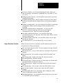
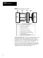
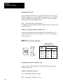
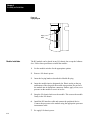
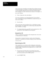
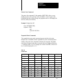
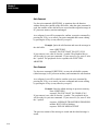
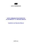
The PLC-2 Family Report Generation Module (cat. no. 1770-RG)
provides bidirectional communication for report generation between a
PLC-2 family processor and an EIA RS-232-C peripheral device. This
allows you to store, delete, edit, report and display messages in PC
processor memory (Figure 1.1).
You can use the report generation (RG) module with any PLC-2 family
processor with any EIZ RS-232-C peripheral device.
Figure 1.1
PLC2 Family Report Generation Module
PLC2
REPORT
GENERATION
BUSY
XMTG
RCVG
PROG
PRPHL
PERIPHERAL
AB
PROCESSOR
11
Chapter 1
Introduction
Report Generation
Allen-Bradley report generation has the capability to display a message or
report when required. Up to 198 messages can be stored in PC processor
memory. When using delimiters, messages can use the current status of
data table bits, bytes or words to report the on/off condition of input or
output devices, analog values, timer/counter accumulated values, real time
or calendar values.
You can initiate the display of stored messages from the keyboard of a
peripheral device when the RG module is in the manual mode of report
generation. Or, stored messages can be displayed automatically when the
RG module is in the automatic report generation mode. In this mode,
program logic initiates the display of a message.
Messages are stored in the area of memory following the user program.
The number of memory words available for messages is equal to the
amount of memory remaining after the user program has been fully
developed. Messages are stored and displayed in a free-form format,
generally in the same format they are entered. Messages can be accessed
when the PC processor keyswitch is in any position. However, automatic
report generation (auto report mode) is operational only when the
processor keyswitch is in the RUN/PROG, RUN or TEST position.
Report generation manual mode is operational when the PC processor
keyswitch is in any position if the RG module is configured for manual
mode.
Module Features
The RG module is compatible with existing report generation
programming and messages stored using the industrial terminal (cat. no.
1770-T1,-T2,-T3). The RG module has additional features, as well. The
RG module’s features include:
Up to 198 messages - you can choose the number of messages to be
stored.
On-Line message store, edit or delete - you can store, edit or delete a
message while the PC processor is executing its program
Message protection - the RG module guards against inadvertent
deletion of a message
Simple programming - only 2 or 3 rungs of programming are required
to display a message by program logic
Real time-clock - you can enter and display the time, and use the time
in a message. Time format is the 24 hour (military) format, 4:15 PM is
16:15 hours
12
Chapter 1
Introduction
Real time calendar - you can enter and display the date, and use the
date in a message. Date format is month/day/year, November 25, 1983
is 11/25/83
Intelligent printer interface - the RG module can monitor a busy/ready
signal from the printer
Peripheral fault detection - the RG module can set bit 027/06 in the PC
processor data table when the module detects a fault in the peripheral
device
Module re-configuration - you can reconfigure the module’s operational
configuration (internal switch settings) from the peripheral device
keyboard
Selectable communications configuration - you can select EIZ
RS-232-C communication (up to 50 feet), or A-B long line
communication (up to 5,000 feet) with the RG module
Selectable communication rates - you can choose from eight
communication rates: 110, 300, 600, 1200, 2400, 4800, 9600 or 19,200
bits per second (baud)
Selectable number of data bits - you can choose either seven or eight
data bits per character
Selectable parity bit - you can choose odd, even or no parity
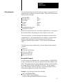
Report Generation Functions
When you enter the correct commands, the RG module performs or lets
you perform the following functions:
MS, 0 message control word file - lets you organize messages in the PC
processor data table
MS message store - lets you create and store a message in PC processor
memory
ME message edit - lets you edit a message in the RG module’s edit
buffer.
MP message print - displays a message in a format as entered
MD message delete - deletes a message
MI message index - displays an index of all messages (or an individual
message) stored in PC processor memory
MR message report - displays a message using current data in report
format
MT message time - lets you enter a time in the RG module’s clock
MC message calendar - lets you enter a date in the RG module’s
calendar
MW Manipulate Word - lets you display and/or change the current
value of a data table word in 4 -digit hex
MB Manipulate Byte - lets you display and/or change the current value
of a data table byte in 8-bit binary
13
Chapter 1
Introduction
MOD module configuration - lets you reconfigure the RG modules
operational configurations (internal switch settings) from the peripheral
device keyboard
14
Chapter
2
Assembly and Installation
General
This chapter outlines procedures for preparation, installation and
connection of the RG module. Specifications are also listed.
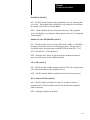
Module Hardware
The RG module is a single slot module with five LED indicators and two
cable connectors on the front panel. Inside the module are five switch
assemblies which you use to select various options.
Status Indicators
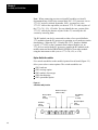
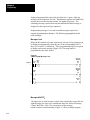
The five LED indicators on the front of the module (Figure 2.1) are useful
for troubleshooting and monitoring module activity. The three green
indicators show module status when receiving and transmitting messages.
The two red indicators show fault status. The five indicators are:
Figure 2.1
Status Indicators
PLC2
REPORT
GENERATION
Busy (Green)
Transmitting (Green)
Receiving (Green)
Processor (Red)
Peripheral (Red)
BUSY
XMTG
RCVG
PROC
PRPHL
BUSY – illuminates when the module has temporarily stopped
transmitting data to the peripheral device because the peripheral
device’s receive buffer is full. This LED blinks during module
initialization, message edit initialization, message edit store, and
message delete.
21
Chapter 2
Assembly and Installation
XMTG – illuminates when the module is transmitting data to the
peripheral device.
RCVG – illuminates when the module is receiving data from the
peripheral device.
PROC – illuminates when a processor fault has occurred or when the
processor is not connected to the RG module.
PRPHL – illuminates when the RG module detects a fault in the
peripheral device.
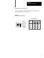
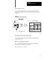
Cable Connections
The front panel of the RG module has two cable connectors. The upper
connector is labeled PERIPHERAL, the lower connector is labeled
PROCESSOR. Typical connections to the peripheral device and
processor are shown in Figure 2.2.
Figure 2.2
Typical Connections
PLC2
REPORT
GENERATION
BUSY
XMTG
RCVG
PROG
PRPHL
RG Interface Cable
cat.no. 1770CH
(925 feet)
Peripheral
Device Cable
Peripheral Printer
..
..
.
.
PERIPHERAL
AB
PROCESSOR
22
Interconnect Cable
cat. no. 1771CN ( 1 1/2 feet)
cat. no. 1771CO (3 1/2 feet)
cat. no. 1771CR (10 feet)
AB
PLC2 Family Processor
or
Communication Adapter
Module (1771KA)
or
Interface Module
(1771KG)
10845I
Chapter 2
Assembly and Installation
Peripheral Connector
The RG module can be connected to either an RS–232–C peripheral
device (50 cable ft max) or to an industrial terminal (cat. no. 1770–T1,
–T2, –T3) using the A–B long line cable (5000 cable ft max). If using the
industrial terminal, set it to alphanumeric mode.
When you connect the RG module to an industrial terminal, you can use
either the 3 ft IT/DH Adapter Cable (cat. no. 1770–CB). Or you can use
up to 5000 ft of A–B Long Line Cable (cat. no. 1770–CR). Connect
either cable to channel B.
RS–232–C Peripheral Device – Connect the peripheral device to the RG
module using the 25 ft RG Interface Cable (cat. no. 1770–CH) supplied
with the module and the peripheral device interconnect cable supplied
with the peripheral device. Connect the cables in series (Figure 2.2). The
RG interface cable conforms to the EIA standard for RS–232–C cables
(Figure 2.3).
23
Chapter 2
Assembly and Installation
Figure 2.3
Pin Functions of Peripheral Cable (cat. no. 1770-CH)
15 Pin
Connector
1770CH
Cable
25 Pin
Connector
Peripheral
Cable
2
3
5
RG
Module
(Data Set)
6
7
8
Peripheral
Device
(Data
Terminal)
11
20
Pin No.
Function (Referred to the RG Module)
2
Receives data from the peripheral device
3
Transmits data to the peripheral device
5
Clear to send, set high (+12V dc)
6
Data set ready, set high (+12V dc)
7
Signal ground, common for all data signals
8
Received line signal detector, set high (+12V dc)
11
Secondary request to send, control line for busy/ready
signal from peripheral device
Data terminal ready, tells RG module when the peripheral
device is readdy to receive or transmit data
20
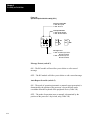
A–B Long Line Operation – Connect the industrial terminal (use in the
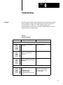
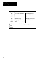
alphanumeric mode) to the RG module using an assembled cable.
Assemble the cable from the required length of double twisted pair 22
gauge bulk cable (cat. no. 1770–CR), a male 15 pin and a male 25 pin
D–shell connector such as Cannon type DB–15P and DB–25P,
respectively, or equivalent (Figure 2.4). Connect the 15 pin end of the
cable to the upper connector labeled PERIPHERAL on the RG module,
and the 25 pin end to the connector labeled CHANNEL B DATA
TERMINAL on the back of the industrial terminal.
24
Chapter 2
Assembly and Installation
Note: The maximum usable length of an A–B long line cable depends on
the communication rate of data transmitted (Table 2.A).
Figure 2.4
Assembled Long-Line Cable
15pin
D shell
male connector
25pin
D shell
male connector
pin
no.
pin
no.
1
RG
Module
Receives Data
3
Receives Data Return
13
Transmits Data
2
Transmits Data Return
14
2
25
Industrial
Terminal
3
18
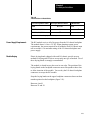
Table 2.A
A-B Long Line Communication Rate/Distance
Distance (feet)
Maximum Rate
(baud)
1000
19,200
3000
9,600
5000
4,800 or less
Processor Connector
Connect the RG module to the processor using interconnect cable (cat. no.
1771– CN,–CO, or –CR). These cables are 1.5 ft., 3.5 ft., and 10 ft.,
respectively. Connect one end to the lower connector labeled
PROCESSOR on the RG module and the other end to the connector
labeled INTERFACE on the front panel of a Mini– PLC–2 or –2/15
controller, or to the connector labeled PROGRAM PANEL on the front
panel of a PLC–2/20, or –2/30 controller.
25
Chapter 2
Assembly and Installation
Note: When connecting previous revision RG modules (revision D,
discontinued June 1984) to the current Mini–PLC–2/15 processor cat. no.
1772–LV series B, released September 1983), you must use a new
1772–TC cable or the equivalent, use the new 1772–TC cable in place of
the 1771–CN, –CO, –CR cable. You can identify the new version of the
1772–TC cable by the absence of pins 10 thru 15, or modify the old
version by removing them.
The RG module can also be connected to either of two special bulletin
1771 modules when the PC processor is operating over a modem or on the
data highway. When the PLC–2 Family/RS–232–C Interface Module
(cat. no. 1771–KG) or the Communication Adapter Module (cat. no.
1771–KA) is used with the PC processor, connect the RG module to the
middle connector labeled PROGRAM INTERFACE on either module
using the interconnect cable (cat. no. 1771–CN,–CO, or –CR).
Option Switch Assemblies
Five switch assemblies on the module’s printed circuit board (Figure 2.5)
allow you to select various options. The switch assemblies are:
SW1 baud rate
SW2 message option
SW3 number of messages
SW4 data bit/parity
SW5 operational option
Figure 2.5
Switch Assembly Location
Number of Messages
Switch Assembly
Data Bit/Parity
Switch
Assembly
Message Option
Switch
Assembly
Operational Option
Switch
Assembly
Baud Rate
Switch
Assembly
SW1
26
SW2
SW3
SW4
SW5
Chapter 2
Assembly and Installation
Baud Rate Switch Assembly, SW1
These switches make the module compatible with the communications
rate of the peripheral device (Figure 2.6).
Figure 2.6
Baud Rate Switch Assembly (SW-1)
Baud Rate Switch Settings
O 1
N
O
F
F
2
3
ON
ON
OFF
ON
OFF
OFF
Switch
Baud
Rate
1
2
3
110
300
600
1200
2400
4800
9600
19200
Off
Off
Off
Off
On
On
On
On
Off
Off
On
On
Off
Off
On
On
Off
On
Off
On
Off
On
Off
On
10827
27
Chapter 2
Assembly and Installation
Message Option Switch Assembly, SW2
Select a message option by turning the appropriate switch on or off
(Figure 2.7). The options are:
Figure 2.7
Message Option Switch Assembly (SW-2)
Echo Back
w ON Enables Echo
w OFF Disables Echo
LF on CR
w ON Enables Line Feed
On Carriage Return
w OFF Disables Line Feed
On Carriage Return
Busy/Ready
w ON Enables Busy/Ready
w OFF Disables Busy/Ready
O 1
N
O
F
F
2
3
4
5
ON
OFF
ON
ON
OFF
OFF
Write Fault In 02706
w ON Sets Bit 027/06 On For
A Peripheral Fault
w OFF Will Not Set Bit 02706 On
For A Peripheral Fault
Enable OnLine MS/MD/ME
w ON Message Store/Delete/Edit May
Be Done In Any Keyswitch
Position (Except Run On
PLC2/15, 2/20, 2/30)
w OFF Message Store/Delete/Edit Can
Only Be Performed When The
Processor Keyswitch Is In The
Prog Position
10828
28
Chapter 2
Assembly and Installation
Echo Back (Switch 1)
ON – The RG module returns to the peripheral device eery character that
it receives. The peripheral device displays every character received from
the module. Set the device for full duplex.
OFF – The RG module does not echo back characters. The peripheral
device will display every character that it transmits only if it is configured
for half duplex.
Enable On–Line MS/MD/ME (switch 2)
ON – The RG module lets you to store (MS), delete (MD), or edit (ME) a
message when the processor is executing its program. The processor’s
keyswitch can be in any position (except RUN on the Mini–PLC–2/15,
PLC–2/20 and PLC–2/30 controllers).
OFF – Message store, delete, or edit can only be performed when the
processor’s keyswitch is in the PROG position.
LF on CR (switch 3)
ON – The RG module enables automatic line feed (LF) on carriage return
(CR) when transmitting to the peripheral device.
OFF – The RG module disables automatic line feed on carriage return.
Write Fault in 027/06 (switch 4)
ON – The RG module sets bit 06 of word 027 on when it detects a
peripheral fault. The RG module resets bit 06 off when the peripheral
fault is corrected.
OFF – Setting the fault bit is disabled.
29
Chapter 2
Assembly and Installation
Busy/Ready (switch 5)
ON – If configured for RS–232–C operation (SW5, switch 1 is off), the
module monitors pin 11 of the peripheral connector. If pin 11 is high, the
module transmits to the peripheral device. If pin 11 is low, the module
stops transmitting to the peripheral device.
OFF – The module does not monitor pin 11.
If configured for Allen–Bradley long line operation (SW5, switch 1 is on),
set this switch off.
Number of Messages Switch Assembly, SW3
These switches select the maximum number of messages that can be
reported automatically. You can select up to 6, 70, 134 or 198 messages.
Refer to Figure 2.8.
Figure 2.8
Number of Messages Switch Assembly (SW-3)
Number of Messages
Switch Assembly (SW3) Settings
ON
O 1
N
O
F
F
2
ON
OFF
1
2
Up to 6
Off
Off
Up to 70
Off
On
Up to 134
On
Off
Up to 198
On
On
ON
OFF
OFF
Switch
Number
of
Messages
10829
Data Bit/Parity Switch Assembly, SW4
These switches select the number of data bits and parity per message
character (Figure 2.9).
Number of Data Bits (switch 1)
ON – The number of data bits is eight.
OFF – The number of data bits is seven.
210
Chapter 2
Assembly and Installation
Parity (switches 2 and 3)
These switches establish the type of parity used by the RG module as
required by the peripheral device. The selections are none, odd or even
(Figure 2.9).
Figure 2.9
Data Bit/Parity Switch Assembly (SW-4)
Number of Data Bits
w ON 8 Data Bits
w OFF 7 Data Bits
O 1
N
O
F
F
2
Parity Switch Settings
3
ON
OFF
ON
ON
OFF
Switch
Parity
OFF
None
Odd
Even
1
2
3
Off
On
Off
Off
Off
On
On
On
1 Disables the module.
Parity
Refer to Table
For factory use only.
1083
Operational Option Switch Assembly, SW5
The operating conditions of the RG module are determined by these
switches (Figure 2.10).
RS–232–C/A–B Long Line (switch 1)
ON – Allen–Bradley long line is selected for use with an industrial
terminal used in the alphanumeric mode only.
OFF – EIZ RS–232–C is selected.
211
Chapter 2
Assembly and Installation
Figure 2.10
Operational Option Switch Assembly (SW-5)
RS232C / ab Long Line
w ON AB Long Line
w OFF RS232C
Auto Report Override
w ON Override Enabled
w OFF Override Disabled
O 1
N
2
3
ON
O
F
F
ON
OFF
ON
OFF
OFF
Message Protect
w ON Stored Messages Cannot
Be Deleted or Edited
w OFF Stored Messages Can
Be Deleted or Edited
Message Protect (switch 2)
ON – The RG module will not allow you to delete or edit a stored
message.
OFF – The RG module will allow you to delete or edit a stored message.
Auto Report Override (switch 3)
ON – The mode of operation (automatic or manual report generation) is
determined by the position of the processor’s keyswitch but can be
overridden from the keyboard of the peripheral device (Table 2.B).
OFF – The mode of operation (auto or manual) is determined by the
position of the processor’s keyswitch, only (Table 2.B).
212
Chapter 2
Assembly and Installation
Table 2.B
Switch Positions for Module Modes
Processor Keyswitch Position
PROG
Auto Report Override Switch 3
ON or OFF
Rg Module Mode
manual
TEST, RUN, RUN/PROG
ON
manual or auto 1
TEST, RUN, RUN/PROG
OFF
auto
1 as determined from the peripheral device keyboard
Power Supply Requirements
The RG module receives all of its power from the I/O chassis backplane.
The module draws 1.0A at +5V DC. When planning system power
requirements, the current required for all modules in an I/O chassis must
not exceed the 6.5A maximum rating of the I/O chassis backplane and
power supply.
Module Keying
Plastic keying bands, shipped with each I/O chassis, provide an easy
method for keying and I/O slot to accept only one type of module. Use of
these keying bands is strongly recommended.
The module is slotted in two places on its rear edge. The position of the
keying bands on the backplane connector must correspond to these slots
to allow insertion of the module. You can key the I/O chassis backplane
connectors to accept the RG module.
Snap the keying bands on the upper backplane connectors between these
numbers printed on the backplane (figure 2.11).
Between 4 and 6
Between 22 and 24
213
Chapter 2
Assembly and Installation
Figure 2.11
Keying Diagram
Keying
Bands
Module Installation
214
2
4
6
8
10
12
14
16
18
20
22
24
26
28
30
32
34
36
The RG module can be placed in any I/O chassis slot except the leftmost
slot. Follow these procedures to install the module:
1.
Set the module switches for the appropriate options.
2.
Remove I/O chassis power.
3.
Insert the keying bands as described in Module Keying.
4.
Insert the module into its designated slot. Plastic tracks on the top
and bottom of the slot guide the module into position. Do not force
the module into its backplane connectors. Rather, apply a firm, even
pressure on the module to seat it in its slot.
5.
Snap the I/O chassis latch over the module. This secures the module
firmly in the I/O chassis.
6.
Install the RG interface cable and connect the peripheral device.
Connect the processor to the module using the appropriate processor
interconnect cable.
7.
Re–apply I/O chassis power.
Chapter 2
Assembly and Installation
The busy LED will blink indicating the module initialization is in
progress. When the busy LED stops blinking (none of the red fault LED is
on), the module has passed internal diagnostics and is ready for use.
Specifications
This section lists the specifications of the RG module
Function
Interfaces a PLC-2 family processor to an EIA
RS-232-C peripheral device
Application
PLC-2 family report generation
Peripheral Channel Communication Rate
(user selectable)
110, 300, 600, 1200, 2400, 4800, 9600, 19.2K
baud
Maximum Distance From Processor
10 cable feet
Module Location
Any slot except the left-most slot of a bulletin
1771 I/O chassis
Power Requirement
1.0A I/O chassis backplane current
Ambient Temperature Range
Operational 0oC to +60oC, +32oF to +140oF
Storage -40oC to +85oC, -40oF to +185oF
Relative Humidity
5% to 95% (without condensation)
Keying
Between 4 and 6, 22 and 24
215
Chapter
3
Module Operation
General
This chapter contains a description of module initialization, the
relationship between the processor keyswitch position and module’s mode
of operation, and an operational overview.
Module Initialization
At initial power-up, the RG module will display the prompt
INITIALIZATION IN PROGRESS. During module initialization, the
busy LED will blink. When initialization has been completed the prompt
COMMAND or AUTOMATIC REPORT GENERATION is displayed
indicating that the module is in manual mode or auto report mode,
respectively. The Module will read its internal switches and configure
itself according to the switch settings.
Processor Keyswitch/Module
Mode of Operation
The RG module will go into automatic report generation if the processor
keyswitch is in the TEST, RUN or RUN/PROG position. However, the
module will go into the manual (command) mode if the keyswitch is in
the PROG position.
If the processor keyswitch is changed to the PROG position, the module
will automatically change from automatic to manual report generation
mode. Also, if the processor keyswitch is changed from the PROG to
RUN/PROG or TEST position, the module will automatically change
from manual to automatic report generation mode.
Every time the mode of operation is changed, the peripheral device
displays a prompt to indicate the current operating mode of the module.
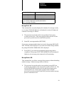
Table 3.A summarizes the settings of the processor keyswitch, on-line
MS/MD/ME switch, auto report override switch, and message protect
switch for each of the report generation commands that you can enter
from the peripheral device keyboard.
31
Chapter 3
Module Operation
Table 3.A
Switch Position for Report Generation
Function
Key Switch Position
Function
Allowed
OnLine
MS/MD/ME
SW22
Message
Protect
SW52
Auto Report
Override
SW53
MS
PROG
TEST, RUN/PROG
RUN
Yes
Yes
No
On
N/A
N/A
On
N/A
MP
PROG
TEST, RUN/PROG
RUN
Yes
Yes
Yes
On
On
MD
PROG
TEST, RUN/PROG
RUN
Yes
Yes
No
On
N/A
Off
N/A
On
N/A
MI
PROG
TEST, RUN/PROG
RUN
Yes
Yes
Yes
MR
PROG
TEST, RUN/PROG
RUN
Yes
Yes
Yes
ME
PROG
TEST, RUN/PROG
RUN
Yes
Yes
No
On
N/A
Off
Off
N/A
Off
Off
N/A
MC
PROG
TEST, RUN/PROG
RUN
Yes
Yes
Yes
MT
PROG
TEST, RUN/PROG
RUN
Yes
Yes
Yes
MB
PROG
TEST, RUN/PROG
RUN
Yes
Yes
No
N/A
N/A
N/A
MW
PROG
TEST, RUN/PROG
RUN
Yes
Yes
No
N/A
N/A
N/A
MOD
PROG
TEST, RUN/PROG
RUN
Yes
Yes
Yes
On
On
Note: The dash () indicates a dipswitch setting of on or off. N/A indicates not applicable. For PLC2 and
MiniPLC2 Controllers having a 3position mode select keyswitch, disregard the RUN entry and
substitute RUN for the RUN/PROG entry.
32
Chapter 3
Module Operation
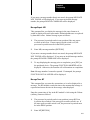
Operational Overview
You must decide what input conditions are necessary to cause a given
message to be displayed. Program these conditions in the message request
rung so that when true, the rung will cause the message’s request bit to be
latched on. Message request bits are found in the upper byte of message
control words (described later). When the RG module detects a message
request bit going from off to on, it causes the peripheral device to display
the requested message. After the message has been displayed, another
rung in the program is used to unlatch (reset) the message request bit.
33
Chapter
4
Programming
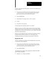
General
With the RG module and a peripheral device you can format, store, edit or
delete messages in PC processor memory. this chapter describes the
commands for organizing, storing, displaying, deleting, indexing and
programming messages in PC processor memory. Editing is discussed in
Chapter 5.
Notational Conventions
The text of this chapter uses the following notational conventions to aid
you when entering commands through the keyboard of the peripheral
device.
A word in brackets represents a single key you would press such as
[ESC] or [RETURN}.
Capital letters not in brackets would be entered as shown.
Punctuation such as commas and arithmetic symbols such as = would
be entered as shown.
These brackets <> define copy that must be entered in proper form, not
as printed. For example <message number> means that you enter the
desired number, not the words, message number.
The peripheral device responds to your commands, either by displaying
prompts or by displaying information resulting from your commands.
Examples of displayed information are shown the way they would be
displayed by a peripheral device.
Commands
The following report generation commands let you assign control words,
store, print, delete, index, and report messages, override switch settings,
enter and display the time and date.
Message Control Word File MS,0
This command lets you assign message control words. Message control
words are 8, 16, or 24 consecutive data table addresses that you select to
control the display of your messages.
41
Chapter 4
Programming
Assign message control words as follows:
1.
The processor keyswitch can be in any position (except RUN on
4-position keyswitches) if auto report override and on-line
MS/MD/ME switches are on. If the auto report override or on-line
MS/MD/ME switch is off, the processor keyswitch must be in the
PROG position.
2.
Press the following keys on the peripheral device:
MS, 0 [RETURN]
At this point, you are required to enter a word address which determines
the starting address of the control word file. The display will prompt the
number of digits required. All digits must be entered including leading
zeros. The RG module will calculate the file length required and display
the message control words and message numbers.
If word addresses have already been assigned for control words, the
peripheral device will display the prompt MESSAGE ALREADY
EXISTS. If this occurs, use the message print command MP,0 (described
later) to display the current control word file. if changes are required,
delete the unwanted file using the delete command MD, 0 (described
later) and re=-enter the control word file using the message store
command MS,0.
For example, select word address 00200 as the beginning address of the
file. Five address digits must be entered in this example.
3.
Enter 00200
WARNING: Message control words should not be used for any
other purpose. Message control words also must not be used in
output image table locations when output or block transfer
modules are placed in corresponding slots. Damage to
equipment and/or personal injury could result.
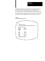
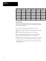
For up to 6 or up to 70 messages, the peripheral device will display the
data in two columns (Figure 4.1), one column for message control words,
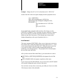
the other column for message numbers. For up to 134 or up to 198
messages, the peripheral device will display the data in four columns
(Figure 4.2) and in six columns (Figure 4.3), respectively.
42
Chapter 4
Programming
When entering an address, if you should enter a key other than 0 thru 7,
the industrial terminal will display the prompt INVALID KEY. Correct
the entry and continue. If you should enter an invalid address (027,
processor word area, or an address outside the boundary of the data table),
the industrial terminal will terminate your entry at that point by displaying
the prompt INVALID ADDRESS. Enter a valid address in its place.
Figure 4.1
Control Word Format for 70 Messages
MS.0
70 MESSAGES SELECTED
MESSAGE CONTROL WORDS (ENTER 5 DIGIT WORD ADDRESS)
ADDRESS = 00200 00207
MESSAGE
MESSAGE
CONTROL
NUMBERS
WORDS
027
16
010 017
00200
110 117
00201
210 217
00202
310 317
00203
410 417
00204
510 517
00205
610 617
00206
710 717
00207
END OF MESSAGE STORE
10856I
43
Chapter 4
Programming
Figure 4.2
Control Word Format for 134 Messages
MS.0
134 MESSAGES SELECTED
MESSAGE CONTROL WORDS (ENTER 5 DIGIT WORD ADDRESS)
ADDRESS = 00200 00217
MESSAGE
CONTROL
WORDS
027
00200
00201
00202
00203
00204
00205
00206
00207
MESSAGE
CONTROL
WORDS
MESSAGE
NUMBERS
16
010 017
110 117
210 217
310 317
410 417
510 517
610 617
710 717
00210
00211
00212
00213
00214
00215
00216
00217
MESSAGE
NUMBERS
1010 1017
1110 1117
1210 1217
1310 1317
1410 1417
1510 1517
1610 1617
1710 1717
END OF MESSAGE STORE
10857I
Figure 4.3
Control Word Format for 198 Messages
MS.0
198 MESSAGES SELECTED
MESSAGE CONTROL WORDS (ENTER 5 DIGIT WORD ADDRESS)
ADDRESS = 00200 00227
MESSAGE MESSAGE
CONTROL NUMBERS
WORDS
027
16
010 017
00200
110 117
00201
210 217
00202
310 317
00203
410 417
00204
510 517
00205
610 617
00206
710 717
00207
MESSAGE MESSAGE
CONTROL NUMBERS
WORDS
00210
00211
00212
00213
00214
00215
00216
00217
1010 1017
1110 1117
1210 1217
1310 1317
1410 1417
1510 1517
1610 1617
1710 1717
MESSAGE MESSAGE
CONTROL NUMBERS
WORDS
00220
00221
00222
00223
00224
00225
00226
00227
2010 2017
2110 2117
2210 2217
2310 2317
2410 2417
2510 2517
2610 2617
2710 2717
END OF MESSAGE STORE
10858I
44
Chapter 4
Programming
The assignment of message control word addresses terminated
automatically when completed.
Control Word - Bit Relationship
To enable the automatic display of messages, a user defined sequence of
events must occur. The programming format to generate messages 1 to 6
is different from that used for more than six messages.
Messages 1 to 6
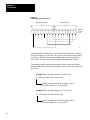
The upper byte of word 027 is used to control messages 1 to 6
(Figure 4.4). Bit 027/10 is the request bit for message number 1, bit
027/11 is the request bit for message number 2 and so on. Bit 027/16, the
busy bit, is set when any of messages 1 to 6 are requested and will remain
set until all requested messages have been displayed. Once all messages
have been displayed, bit 027/17 will remain set for 300ms. It will reset
automatically.
Figure 4.4
Control Word 027 for Messages 1 to 6
Request Bits
17
16
15
14
13
12
11
10
(6)
(5)
(4)
(3)
(2)
(1)
Busy Bit
07
00
Corresponding
Message Numbers
Done Bit
10946
Additional Messages
Message numbers 010-27178 each have a request bit and a done bit in a
message control word that controls eight messages. Message request bits
are located in the upper byte and are set through program logic. The
corresponding done bits are located in the lower byte and are set when the
message is completed or terminated (Figure 4.5).
45
Chapter 4
Programming
Figure 4.5
Extended Message Control Word
Message Request Bits
17
Message Done Bits
10
07
00
Message
Control
Word
10219
Latch and unlatch instructions are used in the ladder diagram program to
initiate the display of a message. In a given scan of the message control
word file by the RG module, requested messages will be displayed in a
given order: the lower the message number, the higher the priority.
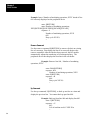
The message number indicates the position of the control word in the
message control word file and the number of the associated request bit in
that word.
Example One: Message number 312 (table 4.A)
3
12-request bit in the control word
control word position in the message control
word file (table 4.A). It is word 203.
Example Two: Message number 1312 (table 4.A)
13
12-request bit in the control word
control word position in the message control
word file (table 4.A). It is word 213.
46
Chapter 4
Programming
Table 4.A
Message Control Word File for 198 Messages
Position in
Control
Word File
Control Word Address
Message
Number
0
200
010 017
1
201
110 117
2
202
210 217
3
203
310 317
4
204
410 417
5
205
510 517
6
206
610 617
7
207
710 717
10
210
1010 1017
11
211
1110 1117
12
212
1210 1217
13
213
1310 1317
14
214
1410 1417
15
215
1510 1517
16
216
1610 1617
17
217
1710 1717
20
220
2010 2017
21
221
2110 2117
22
222
2210 2217
23
223
2310 2317
24
224
2410 2417
25
225
2510 2517
26
226
2610 2617
27
227
2710 2717
Example One
Example Two
47
Chapter 4
Programming
Message Store MS
This command lets you enter and store a message as follows:
1.
The processor keyswitch can be in any position (except RUN on
4-position keyswitches) if auto report override and on-line
MS/MD/ME switches are on. If the auto report override or on-line
MS/MD/ME switch is off, the processor keyswitch must be in the
PROG position.
2.
Enter MS, <message number> [RETURN] from the keyboard of the
peripheral device. The prompt READY FOR INPUT, will be
displayed. Enter your message. If you try to use a message number
that already exists, the peripheral device will display the prompt
MESSAGE ALREADY EXISTS.
You can use delimiters in your message to display the contents of a data
table word, byte, or bit. The delimiter causes the module to interpret the
contents according to the delimiter chosen (Table 4.B). You use a
different delimiter according to the type of interpretation desired (binary,
ASCII, octal, BCD, or hex) and according to the type of address (bit, byte,
or word). When formatting your message, place the proper delimiter
before and after the address containing the contents that you want
displayed. For example, the message *035* PARTS REJECTED uses the
asterisk(*) as the delimiter to display the BCD value of a counter
accumulated value at address 035.
3.
To terminate and store the message, press [ESC][ESC] on the
peripheral device.
Table 4.B
Message Delimiters
Delimiter Symbol
*X X X*
*X X X B*
BCD value of 3digit word address
Octal value of byte at 3digit word address
*X X X X X*
On/off status of 5digit bit address
#X X X X X #
BCD value of 3, 4, or 5digit word address
!X X X X X!
Hex value of 3, 4, or 5digit word address
&X X X X X B&
/X X X X X/
48
Description
Octal value of byte at 3, 4, or 5digit word address
ASCII equivalent of byte at 3,4,or 5digit word
address
Chapter 4
Programming
@X X X X X B@
Hex value of byte at 3, 4, or 5digit word address
^X X X X X X X^
On/off status of 5, 6, or 7digit bit address
$T$
Display time
$C$
Display calendar (date)
Note:
B = 0 or 1 for lower or upper byte respectively at word address
XXX...X = word, byte, or bit address
Message Print MP
This command lets you print (display) the contents of a message exactly
as it is stored. Delimited addresses are displayed as entered. Display the
contents of a message as follows:
1.
The processor keyswitch can be in any position if auto report
override switch is on. If the auto report override switch is off, the
processor keyswitch must be in the PROG position.
2.
Enter MP, <message number>[RETURN]
If you enter a message number that is not stored, the prompt MESSAGE
NOT FOUND will be displayed. If you enter an invalid message number,
the prompt INVALID COMMAND will be displayed.
3.
Press [ESC] if you want to stop displaying the message before
completion. The prompt FUNCTION ABORTED will be displayed.
Otherwise, the message print command is self-terminating.
Message Delete MD
This command lets you delete a message from memory without disturbing
another message. Initiate message delete as follows:
1.
The processor keyswitch can be in any position (except RUN on
4-position keyswitches) if the auto report override switch is on. The
on-line MS/MD/ME switch must be on and the message protect
switch must be off. If auto report override switch is off, the
processor keyswitch must be in the PROG position and the message
protect switch must be off.
49
Chapter 4
Programming
CAUTION: Be careful to identify the correct message number
to be deleted. Once the [RETURN] key is pressed, the message
will be deleted. There is no way to stop the message delete
function once initiated.
2.
Enter MD, <message number>[RETURN]
The peripheral device will display DELETION IN PROGRESS while the
message is being deleted, and the module’s busy LED will blink. When
the message has been deleted, the prompt MESSAGE DELETED will be
displayed. The deleted message number can be re-used to store another
message.
If you enter a message number that is not stored, the prompt MESSAGE
NOT FOUND will be displayed. if you enter an invalid message number,
the prompt INVALID COMMAND will be displayed.
Message Index MI
This command lets you display an index of all message numbers stored
with the corresponding number of memory words used by each message.
Initiate the message index as follows:
1.
The processor keyswitch can be in any position if auto report
override switch is on. If the auto report override switch is off, the
processor keyswitch must be in the PROG position.
2.
Enter MI [RETURN]
The peripheral device displays the message numbers, the number of
words in memory used for each message, and the number of words
remaining in memory.
You can also display the amount of memory used to store a particular
message by entering the following command:
MI, <message number>[RETURN]
410
Chapter 4
Programming
If you enter a message number that is not stored, the prompt MESSAGE
NOT FOUND, will be displayed. If you enter an invalid message
number, the prompt INVALID COMMAND will be displayed.
Message Report MR
This command lets you display the message in the same format as it
would be displayed in auto report mode. Delimited addresses are replaced
by data table values. Initiate message report as follows:
1.
The processor keyswitch can be in any position if the auto report
override switch is on. If auto report override switch is off, the
processor keyswitch must be in the PROG position.
2.
Enter MR,<message number>[RETURN]
If you enter a message number that is not stored, the prompt MESSAGE
NOT FOUND will be displayed. If you enter an invalid message number,
the prompt INVALID COMMAND will be displayed.
3.
To stop displaying the message prior to completion, press [ESC] on
the peripheral device. The prompt FUNCTION ABORTED will be
displayed. Otherwise, the function will self-terminate at completion.
Note: Message number 0 cannot be reported. If attempted, the prompt
FUNCTION NOT ALLOWED will be displayed
Message Time MT
This command lets you enter the current time so it can be displayed in a
message. The RG module records the time at the moment the message is
requested and enters the time in the message when displayed.
Enter the current time of day in the RG module’s clock using the 24 hour
(military) format as follows:
1.
The processor keyswitch can be in any position (except RUN on
4-position keyswitches) if the auto report override switch is on. If
the auto report override switch is off, the processor keyswitch must
be in the PROG position.
2.
Enter MT[RETURN]
411
Chapter 4
Programming
3.
Enter the time. For example, 2:45:50 pm is 14:45:50 and is entered:
144550
4.
Press [ESC] to store the current time.
The following prompts and commands will assist you when entering the
time and date (Table 4.C).
Table 4.C
Additional Commands and Prompts for Entering Time and Date
Command
[RETURN]
Purpose or Description
Prompt
Start over if you make a mistake before
completing the entry.
ENTER DATE NEW
TIME (DATE)
[ESC]
Store a correctly entered time (date).
[ESC]
You pressed this key before the entry was
complete or after making a mistake. Start
over by entering MT (MC) [RETURN].
FUNCTION ABORTED
You pressed an invalid key.
INVALID KEY
You used an invalid format.
INVALID ENTRY
ENTER NEW TIME
(DATE)
Enter current time using steps 1 thru 4 above
when you see this prompt.
X X:X X:X X
Enter date using steps 1 thru 4 in Message
Calendar MC when you see this prompt.
X X/X X/X X
Note: Loss of power to the RG module terminates the time and calendar
functions. They must be re-entered after power is restored. When initially
setting the time or when the time is lost due to a power failure, the prompt
XX:XX:XX will be displayed.
When you want to display the time in a message, enter the time reference
using the elimiter in the key sequence $T$. For example, when formatting
and storing your message, enter the heading “Time:$T$.”
Message Calendar MC
This command lets you enter the date so it can be displayed in a message.
The RG module enters the date when the message is displayed.
412
Chapter 4
Programming
Enter the current date in the RG module’s calendar in the month/day/year
format as follows:
1.
The processor keyswitch can be in any position if the auto report
override switch is on. If auto report override switch is off, the
processor keyswitch must be in the PROG position.
2.
Enter MC[RETURN]
3.
Enter the date. For example, July 16, 1982, is entered:
4.
071682
5.
Press [ESC] to store the date.
Use the prompts and commands in table 4.C as needed.
Note: Loss of power to the RG module terminates the time and calendar
functions. They must be re-entered after power is restored. When initially
setting the date or when the date is lost due to a power failure, the prompt
XX/XX/XX will be displayed.
When you want to display the date in a message, enter the date reference
using the elimiter in the key sequence, $C$. For example, when
formatting and storing your message, enter the header “DATE:$C$.”
Manipulate Word MW
This new command lets you display and/or manipulate the current value
of a data table word in 4-digit hex.
1.
The processor keyswitch can be in any position if the auto report
override switch is on. If the auto report override switch is off, the
processor keyswitch must be in the PROG position.
2.
Enter MW[RETURN]
The peripheral device displays the prompt DATA CHANGE (ENTER 3
DIGIT WORD ADDRESS).
3.
Enter the 3, 4, or 5-digit word address.
413
Chapter 4
Programming
After you enter the word address, the peripheral device displays the data
stored at that address in 4-digit hex. If you know binary/hex conversions,
you can read and/or change any of the 16 bits of the word by reading
and/or changing one or more of the four hex characters. For example, 5 in
hex is 0101 in binary.
4.
Enter or change the value at that address.
If you enter a digit that is out of range (larger than F), the peripheral
device will display the prompt INVALID KEY, terminate the entry, and
ask for a new address.
5.
Store the value.
After you enter the value, the peripheral device will display the prompt
DO YOU WANT TO STORE (Y/N)? and then display the prompt NEW
DATA STORED, accordingly.
6.
To terminate the function, press [ESC] on the peripheral device. The
prompt FUNCTION ABORTED will be displayed.
Manipulate Byte MB
This new command lets you display and/or manipulate the current value
of a data table byte in 8-bit binary.
The procedure for using this function is similar to that of Manipulate
Word above, except that you read and/or change byte data at the address
one bit at a time.
Module Configuration MOD
This command lets you override a module configuration switch setting
(except message protection and auto report override) by reconfiguring the
module through a command from the peripheral device. Override switch
settings as follows:
414
1.
The processor keyswitch can be in any position if auto report
override switch is on. If the auto report override switch is off, the
processor keyswitch must be in PROG position.
2.
enter MOD[RETURN]
Chapter 4
Programming
At this point, the current RG module switch configuration is displayed
with the prompt SELECT LETTER OF OPTION TO BE CHANGED.
You will be prompted through the procedure by the peripheral device.
CAUTION: If you change the baud rate to a rate higher than
your peripheral device can operate, you will have to either
3.
a.
momentarily remove power from the module to revert to the
baud rate determined by switch setting SW1. All configuration
switches default to their physical settings. You will have to
reset the clock and calendar.
b.
reset the baud rate using a peripheral device capable of the
higher rate.
Enter the letter for the switch to be changed.
If you enter a wrong but valid letter by mistake, complete the enter or
press [ESC]. Then start over. Pressing [ESC] terminates the entry without
changing the switch configuration.
4.
Enter the number as required to change the status. The entry is
complete as soon as you enter a valid number.
If you enter a wrong but valid number by mistake, you must repeat steps 3
and 4 to correct it.
5.
Press [ESC] on the peripheral device to exit this function..
Note: Invalid letters or numbers will not be accepted. you will be
prompted to re-enter.
Note: You can display the menu showing the current module switch
configuration values by pressing the letter M.
Programming
Automatic report generation can be programmed to handle multiple or
simultaneous message requests using latch and unlatch instructions. Only
0-to- 1 transitions of the request bits are detected as requested to display
messages. If a message has been requested and displayed, it will not be
415
Chapter 4
Programming
displayed again until the request bit goes from 0 to 1 again. Only one
message can be displayed at a time. Simultaneous requests are handled by
priority-the lower the message number, the higher the priority. The
remaining message requests must remain enabled until their message is
displayed or the request will go unnoticed.
Programming messages 1 to 6 and extended messages requires two
separate programming techniques. The following paragraphs describe
each technique.
Messages 1 to 6
When the RG module is in auto report mode, any one of six messages can
be displayed automatically when any one of the corresponding bits 10
thru 15 in word 027 is latched on. Three programming rungs are required
to display each stored message (Figure 4.6). The rungs must be
programmed in the order shown.
Figure 4.6
Sample Program, Messages 1 to 6
Rung No.
1
Busy
Event Bit
265
027
04
16
Storage
Bit
2
3
Bit
027
Message
Request
Bit
027
L
10
Message
Request
Bit
027
U
10
Storage
Bit
17
Messages 01027178
The upper byte of each message control word contains the request bits for
eight messages, the lower byte contains the done bits. Refer to Message
Control Word File - MS, 0 for a description of the message
number/control word relationship. Figure 4.7 shows a sample program
416
Chapter 4
Programming
that can be used to display each message. Table 4.D presents a
description of the sample program.
Figure 4.7
Sample Program, Messages 01027178
Rung No.
1
Event
265
04
2
Message
Request
Bit
200
L
10
Message
Request
Bit
200
U
10
Message
Done
Bit
200
Event
265
04
00
Table 4.D
Program Description
Rung
Description
1
When bit 265/04 is on, the rung is true and bit 200/10 is latched
on. Bit 200/10 will remain latched on even when its rung is
false until it is reset by rung 2. For this example, bit 200/10
controls the generation of message number 010.
2
When message number 010 has been completed, its done bit
(200/00) is set on. This causes rung 2 to be true and unlatches
the message request bit 200/10. When a 1 to 0 transition of the
message request bit is detected, the done bit (200/00) is reset
to 0.
417
Chapter
5
Editor Function
General
The RG module allows you to edit messages already stored in PLC-2
family processor memory. You can edit, insert, or remove the wording of
existing messages one line at a time using a peripheral device. you can
also go directly to the beginning or end of the message, quite the edit
procedure and leave the message unchanged, or store the edited message.
To edit a message you copy it into the module’s edit buffer, perform the
edit, then store the edited message in memory. The procedure will be
described later in Editing Commands.
Edit Buffer
The RG module’s edit buffer stores up to 23001 characters. A character is
defined as a single letter, digit, punctuation mark or space. When the edit
buffer is full, you cannot add characters to an existing line nor add
additional lines unless you first remove existing lines to make room for
new characters or lines. If you attempt to enter more than 2300
characters, the peripheral device will display the prompt BUFFER FULL
and the edit buffer will not store additional characters.
If it is necessary to edit a message that exceeds 2300 characters, you must
create an new message(s) for the balance of characters exceeding 2300
because the original message is erased when you (re)store the edit buffer
contents in PC processor memory. The prompt BUFFER LIMIT
EXCEEDED is displayed when you attempt to copy a message larger than
2300 characters into the edit buffer.
You can terminate the edit function at this point without erasing the
message in PC processor memory using the quit command. Or, you can
divide the original message into two (or more) messages. Retain the
original message number for the first part of the message. Assign a higher
message number to the balance of the message. Then when these
messages are requested, they can be displayed in correct order.
1
The buffer size was 2400 characters in revision A-E.
51
Chapter 5
Editor Function
Line Numbering
You must designate the end of each line when entering characters into the
edit buffer. Press the [RETURN] or [RETURN][LINE FEED] keys to
designate the end of each line. All characters entered between two
successive [RETURN] keys are the text for that line.
The edit buffer assigns a number to each line in consecutive order. The
ranges of available line numbers are 000 thru 999 and 1000 thru 2300.
You can access any assigned line number using the commands described
later by entering the line number using leading zeros where necessary. For
example, use leading zeros for line seven, entered as 007.
Protect Messages
The message protect configuration switch, SW5 position 2, must be off to
use the message edit function. If this switch is on, the peripheral device
will prompt you with RG MESSAGE PROTECT ENABLED and the
module will prevent you from using the edit function.
Switch 5 position 2 can be switched on by removing the module from the
I/O chassis, opening the switch cover plate and locating the switch on the
top of the circuit board. Refer to Operational Option Switch Assembly,
for additional information on locating and setting this switch.
Processor Keyswitch Position
You can use the RG module’s editing function when the processor is in an
operating mode that allows programming changes including on-line data
change (table 3.A)
You can use the editing commands on-line while the processor is
operating, provided the RG module’s on-line MS/MD/ME switch and the
auto report override switch (SW2-2 and SW5-3 respectively) are both on.
If either switch (SW2-2 or SW5-3) is off, the processor keyswitch must be
switched to the PROG position in order to use the edit function.
52
Chapter 5
Editor Function
Editing Commands
You can edit messages stored in PC processor memory using an RS-232-C
peripheral device connected to the RG module. This section describes the
following edit commands:
Message Edit
Message Print
Line Print
Change
Insert
Remove
Expanded Message Print
Expanded Line Print
Up
Down
Top
Bottom
Quit
Store
Because the response between you and the peripheral device is interactive,
the text that follows will prompt your entry using the word “enter:”.
The word “response:” is used to designate the displayed response of the
peripheral device. Also, the peripheral device displays a>(greater than)
symbol at the beginning of a line to prompt your next entry of a
command. When the word “module:” is used, observe the illuminated
LED.
The following message, number 010, is used to illustrate edit command
examples.
Station 27
Cycle time XX.XX min
Tool wear .XXXX in
Tool life XXX.X hr
Duty cycle XX.X%
Message Edit Command
Use the message edit command, ME, <message number 4 3/8[RETURN],
to copy a message from PC processor memory into the RG module’s edit
buffer. The peripheral device tells you that the message is being copied by
the prompt INITIALIZING EDITOR FUNCTION. The RG module’s
busy LED will blink. After the message is copied, the peripheral device
automatically displays the first line of the message.
Example: Copy message 010 into the edit buffer.
enter: ME,010[RETURN]
module: BUSY LED is blinking
response: INITIALIZING EDITOR FUNCTION
53
Chapter 5
Editor Function
response: 000:
Station 27
>
The remaining ten edit commands can now be used.
Print Command
Four print commands are available, print multiple lines, expanded
message print, print a line, and expanded line print.
Print Multiple Lines Command
The print multiple lines command, P[RETURN], allows you to display
(print) the entire message in the edit buffer from the current line to the last
line in the edit buffer with one command.
Example: Display the message in the edit buffer.
enter: P[RETURN]
response:>P
000:
Station 27
001:
Cycle time XX.XX min
002:
Tool wear .XXXX in
003:
Tool life XXX.X hr
004:
Duty cycle XX.X%
005:
EOB
>
You can press [ESC] to stop the display on any line before the last line.
The peripheral device will finish displaying the line and present the >
prompt, indicating it is ready for your next command.
54
Chapter 5
Editor Function
Print a Line Command
The print a line command, P<line number>[RETURN], allows you to
display any line of the message in the edit buffer. If you request a line
beyond the last line of the message, the peripheral device will display the
last line, EOB (end of buffer).
Example: Display line 003.
enter: P003[RETURN]
response: >P003:
003:
Tool life XXX.X hr
>
Expanded Print Commands
The expanded message print command operates similar to the print
multiple lines command, and the expanded line print command operates
similar to the print a line command, with this one exception. The alpha
equivalent of control codes that you stored in hex are displayed between
<> symbols (Table 5.A). For example, the control code BEL, stored as 07
hex, would be displayed as <G>.
Table 5.A
Control Codes
Control Code
Hex Value
Display
Control Code
Hex Value
Display
NUL
00
<@>
DLE
10
<P>
SOH
01
<A>
DC1
11
<Q>
STX
02
<B>
DC2
12
<R>
ETX
03
<C>
DC3
13
<S>
EOT
04
<D>
DC4
14
<T>
ENQ
05
<E>
NAK
15
<U>
ACK
06
<F>
SYN
16
<V>
BEL
07
<G>
ETB
17
<W>
BS
08
<H>
CAN
18
<X>
HT
09
<I>
EM
19
<Y>
55
Chapter 5
Editor Function
Control Code
Hex Value
Display
Control Code
Hex Value
Display
LF
0A
<J>
SUB
1A
<Z>
VT
0B
<K>
ESC
1B
<[>
FF
0C
<L>
FS
1C
<>
CR
0D
<M>
GS
1D
<]>
SO
0E
<N>
RS
1E
<>
SI
0F
<O>
US
1F
<_>
Change Command
The change command, C[RETURN], allows you to change a line of a
message. You must first display the line to be changed using the print a
line, up, or down command.
At the completion of the change, you must make two entries:
{RETURN] or [RETURN][LINE FEED] to designate the end of the
line.
[ESCAPE][ESCAPE] to designate the end of the change.
If you do not press the [ESCAPE] key twice in succession, the RG
module will consider subsequent entries as part of the change.
When changing a line, you can replace as many characters as necessary
provided you do not exceed the 2300 character limit of the edit buffer.
The peripheral device displays the next line in the edit buffer after you
complete the change.
56
Chapter 5
Editor Function
Example: Change line 003 to “Life of machine tool #1 XXX.X hr”
Assume line 003 is the last response displayed on the peripheral device.
enter: C[RETURN]
enter: Life of machine tool #1 XXX.X hr
[RETURN][LINE FEED][ESCAPE][ESCAPE]
RESPONSE: >C
Life of machine tool # 1 XXX.X hr
004:
Duty cycle XX.X%
>
If you should make a mistake while entering a line change, use the
[DELETE] or [RUBOUT] key. Each time you press either key, it deletes
the previous character from the edit buffer. Either key can be used to
delete an entire line if necessary. (The deletion may or may not be
displayed depending on the type of peripheral device.)
Insert Command
The insert command, I[RETURN], allows you to insert one or more new
lines ahead of the current line displayed by the peripheral device. A line
can be inserted ahead of the first line, 000. When you insert a new line
(or several new lines), the RG module automatically adjusts the
numbering or all subsequent lines. The peripheral device then displays
the next line in the edit buffer
After you have inserted the needed line(s), you must make two entries:
[RETURN] or [RETURN][LINEFEED] to designate the end of the
line.
[ESCAPE][ESCAPE] to designate completion of the insert.
If you do not press the [ESCAPE]key twice in succession, the RG module
will consider subsequent entries as part of the insert.
You can insert as many lines as necessary provided you do not exceed the
2300 character limit of the edit buffer.
57
Chapter 5
Editor Function
Example: Insert “Number of machining operations, XXX” ahead of line
004 currently displayed on the peripheral device
enter: I[RETURN]
enter: Number of machining operations,
XXX[RETURN][LINE FEED][ESCAPE][ESCAPE]
response: >I
Number of machining operations, XXX
005:
Duty cycle XX.X%
>
Remove Command
Use the remove command, R[RETURN] to remove (delete) an existing
line of a message. First display the line to be removed, then use the
remove command. After the line has been removed, the RG module
automatically adjusts the numbering of all subsequent lines. The
peripheral device then displays the next line in the edit buffer:
Example: Remove line 004, “Number of machining
operations, XXX.”
enter: P004[RETURN]
response: 004:
Number of machining operations, XXX
enter: R[RETURN}
response: >R
004:
Duty cycle XX.X%
>
Up Command
Use the up command, U[RETURN], to back up one line at a time and
display the previous line. You cannot back up past line 000.
Example: Back up from line 004 and display line 003.
enter: U[RETURN}
response: >U
003:
Life of machine tool #1 XXX.X hr
>
58
Chapter 5
Editor Function
Down Command
Use the down command, D[RETURN], to move down one line at a time
and display the next line in the edit buffer. You cannot go beyond the last
line, EOB.
Example: Move from line 003 to display line 004.
enter: D[RETURN}
response: >D
004:
Duty Cycle XX.X%
>
Note: If you wish to move several lines in either direction use the print a
line command, P<line number>[RETURN}.
Top Command
Use the top command T[RETURN], to return to the first line of the
message, line 000, and display it.
Example: Return to line 000.
enter: T[RETURN]
response: >T
000:
Station 27
>
Bottom Command
Use the bottom command, B[RETURN], to go to the last line of the
message, EOB, and display it.
Example: Go to EOB
enter: B[RETURN]
response: >B
005
EOB
>
59
Chapter 5
Editor Function
Quite Command
Use the quit command, Q[RETURN], to terminate the edit function
without storing the contents of the edit buffer. when the quite command is
used, the contents of the edit buffer are erased and the original message in
PC processor memory remains unchanged.
As a safeguard, you will be prompted to confirm your quite command by
pressing the Y key, or to cancel your quite command and resume editing
by pressing the N key (or any other key except Y).
Example: Quite the edit function and erase the message in
the edit buffer.
enter: Q[RETURN]
response: DO YOU WANT TO QUIT (Y/N)?
If your answer is no, enter N after the ? symbol. The peripheral device
will be ready for your next command. If your answer is yes, enter Y after
the ? symbol. The peripheral device responds with FUNCTION
ABORTED.
Store Command
Use the store command, S[RETURN}, to store the edit buffer contents
(edited message) in PC processor memory and terminate the edit function.
As a safeguard, you will be asked to confirm your store command by
pressing the Y key, or to cancel your store command and resume editing
by pressing the N key (or any other key except Y).
Example: Store the edited message in processor memory.
enter: S[RETURN]
response: DO YOU WANT TO STORE (Y/N)?
If your answer is no, enter N after the ? symbol. The peripheral device
will be ready for your next command. If your answer is yes, enter Y after
the ? symbol.
response: MESSAGE TRANSFER IN PROGRESS
module: BUSY LED is blinking
response: END OF MESSAGE EDIT
The previous content of the message is erased and the edited message is
stored.
510
Chapter 5
Editor Function
Summary of Edit Commands
Table 5.B
Edit Commands
Title
Command Entry
Description
Message Edit
ME,
<message #>
[RET]
Print Multiple
Lines
P [RET]
Displays current line to last line
Expanded
Massage Print
E [RET]
Displays current lint to last line displaying control
codes
Print a Line
P <line #> [RET]
Displays the designated line
Expanded Line
Print
E<line #> [RET]
Displays the designated line displaying control
codes
Change
C [RET]
Allows you to change a line
Insert
I [RET]
Allows you to insert a line
Remove
R [RET]
Removes the current line
Up
U [RET]
Backs up one line
Down
D [RET]
Moves down one line
Top
T [RET]
Moves to top (first line)
Bottom
B [RET]
Moves to bottom (last line)
Quit
Q [RET]
Allows you to stop editing without changing a
message
Store
S [RET]
Stores edited message in processor memory and
terminates the function
Copies message from processor memory into
module so you can edit its contents
511
Chapter
6
Troubleshooting
General
By observing the LEDs on the front of the report generation module,
many module or module related malfunctions can be located and
corrected. Refer to Table 6.A. If the module appears to be
malfunctioning, consult with your nearest Allen–Bradley Customer
Support Services or Sales Office.
Table 6.A
Troubleshooting Chart
Indication
Description
Recommended Action
During Power-up with no cables attached
BUSY
XMTG
RCVG
PROC
PRPHL
ALL LEDS except RCVG blink on
and off once
None, normal operation
BUSY
XMTG
RCVG
PROC
PRPHL
PROC LED turns on and stays on.
Module has passed internal
diagnostics
None, normal operation
BUSY
XMTG
RCVG
PROC
PRPHL
All LEDs except RCVG remain
flashing. Module has failed internal
diagnostics
Replace module
After power-up diagnostics and with cables connected
BUSY
XMTG
RCVG
PROC
PRPHL
PROC FAULT indicated processor
fault 1
COMM FAULT indicates
communication fault1
NOISE FAULT indicates electrical
noise1
Check cables for proper connection
between processor and report
generation module, or check
processor for fault.
61
Chapter 6
Troubleshooting
After power-up diagnostics and with cables connected
BUSY
XMTG
RCVG
PROC
PRPHL
Fault detectd by oeripheal device
Check peripheral device cablr
connection t report generation
module.
Peripheral device has an internal
fault.
BUSY
XMTG
RCVG
PROC
PRPHL
Module does not work:
• Parity switch setting is invalid
• Busy/Ready switch is on when
peripheral device has no busy/ready
signal
Change parity switches 2 and 3 to
valid setting.
Turn off Busy/Ready switch 5.
Legend
= not illuminated
= flashing
= illuminated
62
1The RG module generates these prompts and transmit
them to the peripheral device for display.
Index
Symbols
**Empty**, 61
L
Line numbering, 52
Long-line operation, 24
A
Auto report mode, 12, 212, 31
M
Manual mode, 12, 212, 31
C
Cables and connections, 22
Commands
Editing, 53
Report generation, 41
Communications rate, 25, 27
Connector, Processor, 25
Connectors, Peripheral, 23
Control words, assignment of, 41
D
Delete key, 57
Delimiter, 48
E
Edit buffer, 51
I
Indicators, 21
Initialization, 31
Installation, 214
K
Keying, 213
Message request/done bits, 45
Module configuration, from keyboard, 414
Module features, 12
Module modes of operation, 31
N
Notational conventions, 41
P
Power requirements, 213
Processor keyswitch positions, 32, 52
Programming examples, 416
Protect messages, 52
R
Report generation funcions, 13
RS-232-C peripheral device, 23
S
Switch assemblies, 26
T
Time/date prompts and commands, 412,
413
Troubleshooting, 61
AllenBradley, a Rockwell Automation Business, has been helping its customers improve
productivity and quality for more than 90 years. We design, manufacture and support a broad
range of automation products worldwide. They include logic processors, power and motion
control devices, operator interfaces, sensors and a variety of software. Rockwell is one of the
world's leading technology companies.
Worldwide representation.
Argentina • Australia • Austria • Bahrain • Belgium • Brazil • Bulgaria • Canada • Chile • China, PRC • Colombia • Costa Rica • Croatia • Cyprus • Czech Republic • Denmark •
Ecuador • Egypt • El Salvador • Finland • France • Germany • Greece • Guatemala • Honduras • Hong Kong • Hungary • Iceland • India • Indonesia • Ireland • Israel • Italy •
Jamaica • Japan • Jordan • Korea • Kuwait • Lebanon • Malaysia • Mexico • Netherlands • New Zealand • Norway • Pakistan • Peru • Philippines • Poland • Portugal • Puerto
Rico • Qatar • Romania • RussiaCIS • Saudi Arabia • Singapore • Slovakia • Slovenia • South Africa, Republic • Spain • Sweden • Switzerland • Taiwan • Thailand • Turkey •
United Arab Emirates • United Kingdom • United States • Uruguay • Venezuela • Yugoslavia
AllenBradley Headquarters, 1201 South Second Street, Milwaukee, WI 53204 USA, Tel: (1) 414 3822000 Fax: (1) 414 3824444
Publication 1770-6.5.5 - March 1986
Supersedes Publication 1770-815 - July 1983
PN 955099-27
Copyright 1986 AllenBradley Company, Inc. Printed in USA
Publication 1770-6.5.5 - March 1986