1
1
Content
Overview............................................................................................................................................3
1. Shape and connection...............................................................................................................4
2. Operation panel.........................................................................................................................14
3. Installation ..................................................................................................................................17
4. Control and operation .............................................................................................................18
5. Measuring and display ............................................................................................................21
6. Alarms..........................................................................................................................................22
7. Configuration .............................................................................................................................23
8. Communication.........................................................................................................................25
9. Technical parameters ..............................................................................................................28
10. Troubleshooting......................................................................................................................29
2
Overview
TU510 controller is an auto-transfer controller integrate measure/display, control, and three-remote function.
This controller including three type: TU510a-MG/MM/GG,used for auto transfer control for two power supply
system between Mains and Gens, Mains and Mains, or Gen and Gens. It has the following function:
Micro-computer control, complete digital technology
Configure the running mode of the controller according to the panel keys.
According to the LED indicate the running status and running mode of the controller directly.
Configure the running parameters according to the panel LED indicating and keys.
Display the measuring data including voltage and frequency by LED.
Interface RS485 port to PC (required RS485/RS232 transformer) can read/write, rectify all settings and
data.
This manual is only available for TU510 auto transfer controller, anyone should read this manual
carefully before use.
In order to avoid repetition in specification in this manual:
1.
Name
TU510a-MG
TU510a-GG
TU510a-MM
1# resource
Mains
1# Gen
1# Mains
2# resource
Gen
2# Gen
2# Mains
2.
Short
Type
MG
TU510a-MG
GG
TU510a-GG
MM
TU510a-MM
3
1. Shape and connection
The Controller is integrated closely by die-casting panel made of prevent-burning, high-strength plastic and
steel shell that has been spurt power. All connection lines of the controller connect through pin-like port with
lock; make the device can be connected, moved, maintained and replaced easily and conveniently.
1.1 Size
Panel
W205mm x H156mm
Hatch
W186mm x H138mm
Thickness
D60mm(not connect)
A
1 2 3 4 5 6 7
RS-CONNECTOR
B
8 9
C
10 11 12 13 14 15 16
D
17 18 19 20 21 22 23 24 25 26 27
Note: the shell of this controller should properly grounded, well low competence could reduce the surge of
the electricity system and transient procedure impact the meter.
4
1.2 MG connection port
Pin No.
Function
Signal
Line
A1
Mains Phase A V input
0-300VAC
1mm²line
A2
Mains Phase B V input
0-300VAC
1mm²line
A3
Mains Phase C V input
0-300VAC
1mm²line
A4
Mains N zero line
A5
Relay normal open point(NO)
Transform switch at mains side
1.5mm²line
A6
Relay common point(COM)
control output
1.5mm²line
A7
Relay normal closed(NC)
16A250VAC
1.5mm²line
B8
standby
1mm²line
B9
standby
1mm²line
B10
Gen. Phase A voltage input
0-300VAC
1mm²line
B11
Gen. Phase B voltage input
0-300VAC
1mm²line
B12
Gen. Phase C voltage input
0-300VAC
1mm²line
B13
Gen. N zero line
B14
Relay normal open point (NO)
B15
Relay common point (COM)
B16
Relay normal closed point (NC)
D17
Common point for status input signal
D18
Mains side aux contact signal
Low potential available
1mm²line
D19
Gen. Side aux contact signal
Low potential available
1mm²line
D20
standby
Low potential available
1mm²line
D21
standby
Low potential available
1mm²line
D22
standby
Low potential available
1mm²line
D23
Start output {COM}
Control the start output of the
1mm²line
D24
Start input{N/O}
generator
1mm²line
D25
Standby for output{COM}
Standby for output
1mm²line
D26
Standby for output{N/O}
5A30VDC
1mm²line
D27
Connect to external ground
1mm²line
1mm²line
Transform switch at Gen side
control output 16A250VAC
1.5mm²line
1.5mm²line
1.5mm²line
1mm²line
5A30VDC
1.5mm²line
5
(3P&N)
Gen
Available for TGME or transform switch of AC connector type
6
13
F6
23
RL4
10
11
24
Genset start signal
N2
L6
F7
F8
14
16
27
MT
Note:
17
18
MT
8
15
9
RL2
DC resource(standby)
(8-35VDC)
F9
(2A)
12
MX
19
7
M1/M2
(aux contact for transform switch)
RL1
5
Note: controller must be grounded properly
TU510a-MG
XF
XF (close)
MX (de-exciter)
XF
MX
MN
MN
MN (no voltage)
MT (Storage motor)
F4
4
F1
F2
F3
6
1
2
3
N1
L3
L2
N3
L1
L9
L5
L8
L4
F5
L7
Load(3P&N)
Mains
(3P&N)
1.3 MG typical wiring diagram
Available for transform switch of breaker type
7
(3P&N)
Gen
13
23
RL4
10
F5
24
11
F6
Genset start signal
N2
L6
8
15
F8
9
RL2
14
16
DC resource(standby)
(8-35VDC)
F9
(2A)
12
F7
27
Note:
17
18
MT
MX (de-exciter)
MX
19
7
M1/M2
(aux contact for transform switch)
RL1
5
Note: controller must be grounded properly
TU510a-MG
XF
MX
MN
XF (close)
XF
MN (no voltage)
MT (Storage motor)
MN
MT
F4
4
F1
F2
F3
6
1
2
3
N1
L3
L2
N3
L1
L9
L5
L8
L4
L7
Load(3P&N)
Mains
(3P&N)
1.4 GG connection port
Pin No.
Function
Signal
Line
A1
1# Gen. Phase A V input
0-300VAC
1mm²line
A2
1# Gen. Phase B V input
0-300VAC
1mm²line
A3
1# Gen. Phase C V input
0-300VAC
1mm²line
A4
1# Gen. N zero line
A5
Relay normal open point(NO)
Transform switch 1# Gen.
1.5mm²line
A6
Relay common point(COM)
Side switch control the output
1.5mm²line
A7
Relay normal closed(NC)
16A/250VAC
1.5mm²line
B8
working source +B
B9
working source -B
B10
2# Gen. Phase A voltage input
0-300VAC
1mm²line
B11
2# Gen. Phase B voltage input
0-300VAC
1mm²line
B12
2# Gen. Phase C voltage input
0-300VAC
1mm²line
B13
2# Gen. N zero line
B14
Relay normal open point
Transform switch 2# Gen.
1.5mm²line
B15
Relay common point
Side switch control the output
1.5mm²line
B16
Relay normal closed point (NC)
16A/250VAC
1.5mm²line
D17
common point for status input signal
D18
1mm²line
8~35VDC
1mm²line
1mm²line
1mm²line
1mm²line
1# Gen. Side aux contact signal
Low potential available
1mm²line
D19
2# Gen. Side aux contact signal
Low potential available
1mm²line
D20
1# generator fault input
Low potential available
1mm²line
D21
2# generator fault input
Low potential available
1mm²line
D22
Remote start input
Low potential available
1mm²line
D23
2# start output {COM}
Control 2# generator
D24
2# start output {N/O}
output
D25
1# start output {COM}
Control 2# generator
D26
1# start output {N/O}
output
D27
connect to external ground
start
5A/30VDC
5A/30VDC
1mm²line
1mm²line
start
1mm²line
1mm²line
1.5mm²line
8
(3P&N)
Gen
Available for TGME or transform switch of AC connector type
9
13
F6
23
RL4
10
11
24
Genset start signal
N2
L6
F7
F8
14
16
27
MT
Note:
17
18
MT
8
15
9
RL2
DC resource(standby)
(8-35VDC)
F9
(2A)
12
MX (de-exciter)
MX
19
7
M1/M2
(aux contact for transform switch)
RL1
5
Note: controller must be grounded properly
TU510a-MG
XF
XF
MX
MN
XF (close)
MN
MN (no voltage)
MT (Storage motor)
F4
4
F1
F2
F3
6
1
2
3
N1
L3
L2
N3
L1
L9
L5
L8
L4
F5
L7
Load(3P&N)
Mains
(3P&N)
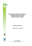
1.5 GG typical wiring diagram
Available for transform switch of breaker type
10
(3P&N)
2# Gen
13
F5
F6
F7
F8
14
16
8
9
27
Note:
M1/M2
19
21
7
5
F4
4
F1
F2
F3
L1
N2
TO GEN.1
Genset start signal
TO GEN.2
25
15
RL3
12
23
24
11
RL4
10
26
RL2
DC source
(8-35VDC)
F9
(2A)
(aux for switch)
2#
Gen fault
20
MX
RL1
(Short when nonuse)
Remote start signal
22
6
Note: controller must be grounded properly
17
1#
Gen fault
MX
18
XF (close)
MX (de-exciter)
XF
TU510a-GG
MN
MN (no voltage)
MN
XF
MT
MT (storage motor)
MT
1
2
3
N1
L3
N3
L2
L9
L6
L8
L5
L4
L7
Load(3P&N)
1# Gen
(3P&N)
1.6 MM typical wiring diagram
Pin No.
Function
Signal
Line
A1
1# mains phase A voltage input
0-300VAC
1mm²line
A2
1# mains phase B voltage input
0-300VAC
1mm²line
A3
1# mains phase C voltage input
0-300VAC
1mm²line
A4
1# mains N zero line
A5
Relay normal open point (NO)
Transform switch at 1# mains
1.5mm²line
A6
Relay common point (COM)
side output
1.5mm²line
A7
Relay normal close point (NC)
16A250VAC
1.5mm²line
B8
standby
1mm²line
B9
standby
1mm²line
B10
2# mains phase A voltage input
0-300VAC
1mm²line
B11
2# mains phase B voltage input
0-300VAC
1mm²line
B12
2# mains phase C voltage input
0-300VAC
1mm²line
B13
2# mains N zero line
B14
Relay normal open point (NO)
Transform switch at 1# mains
1.5mm²line
B15
Relay common point (COM)
side output
1.5mm²line
B16
Relay normal close point (NC)
16A250VAC
1.5mm²line
D17
Status input signal common point
D18
1# mains side aux contact signal
Low potential available
1mm²line
D19
2# mains side aux contact signal
Low potential available
1mm²line
D20
standby
Low potential available
1mm²line
D21
standby
Low potential available
1mm²line
D22
standby
Low potential available
1mm²line
D23
Aux output{COM}
5A30VDC
1mm²line
D24
Aux output{N/O}
1mm²line
D25
Aux output {COM}
1mm²line
D26
Aux output {N/O}
D27
Connect to external ground
1mm²line
1mm²line
1mm²line
5A30VDC
1mm²line
1.5mm²line
11
(3P&N)
Gen
Available for TGME or transform switch of AC connector type
12
13
23
RL4
10
F5
24
11
F6
Genset start signal
L4
L5
L6
N2
8
15
F8
9
RL2
14
16
DC resource(standby)
(8-35VDC)
F9
(2A)
12
F7
27
17
18
19
RL1
7
(aux contact for transform switch)
M1/M2
MX
XF
5
Note: controller must be grounded properly
TU510a-MG
MX (de-exciter)
MX
MN
XF (close)
MN (no voltage)
XF
MN
N3
MT
L9
Note:
MT (Storage motor)
L8
MT
L7
Load(3P&N)
6
F4
4
1
F1
2
F2
3
F3
L1
L2
L3
N1
Mains
(3P&N)
1.7 MM typical wiring diagram:
Available for transform switch of breaker type
13
(3P&N)
Gen
13
23
RL4
10
F5
24
11
F6
Genset start signal
N2
L6
8
15
F8
9
RL2
14
16
DC resource(standby)
(8-35VDC)
F9
(2A)
12
F7
27
Note:
17
18
MT
MX
19
7
M1/M2
(aux contact for transform switch)
RL1
5
Note: controller must be grounded properly
TU510a-MG
XF
XF (close)
MX (de-exciter)
XF
MX
MN
MN (no voltage)
MT (Storage motor)
MN
MT
F4
4
F1
F2
F3
6
1
2
3
N1
L3
L2
N3
L1
L9
L5
L8
L4
L7
Load(3P&N)
Mains
(3P&N)
2. Operation panel
The operation panel including three parts: LED display for measuring parameters, operating keys and
LED indicate for running status.
2.1 LED display and its keys.
Two lines of three bits LED on both left and right side simultaneously display the phase voltage and
frequency of each phase, scroll page to refer voltage for other phase, and the LED, together with the
operating keys, provide the user a friendly interface to configure the running parameters.
2.2 Menu system and LCD for running status
Function
Name
Enter next submenu/rectify/confirm
Scroll up page menu/increase value
Scroll down page menu/decrease value
2.3 MG Operating keys and LED
Function
Name
AUTO key/indicator light
This key used in AUTO mode, when controller in
this mode, the LED above the key illuminate. Prior
to mains, if mains in normal, then mains supply; if
mains fault occur, Gen supply.
MAN key/indicator light
This key used in MAN mode for setting. When
controller in this mode, the LED above the key
illuminate, controller choose mains supply or Gen
supply
according
to
“TO
MAINS”and“TO
GENSET”key
TEST key/indicator light
This key used in test mode. When controller in this
mode, the LED above the key illuminate. In this
mode, controller simulates mains supply.
TO MAINS key
When the controller in MAN mode, when the mains
voltage is normal, press this key switch to mains
supply, the LED above the key illuminate.
TO GENSET
When the controller in MAN mode, if the Gen
voltage is normal, press this key switch to Gen
supply, the LED above the key illuminate.
14
L. TEST key
Test lamps, press this key all lamps should
illuminate, if not, fault occurs.
Note: LED above “TO MAINS”and“TO GENSET”keys indicate related close relay action.
2.4 GG Operating keys and LED
Function
Name
GEN.1Key/indicator light
This key used for 1# Gen. priority mode. LED
above the key illuminate when controller in this
mode. 1# Gen. priority. When 1# Gen. normal, 1#
Gen. supply; if 1# Gen failed, 2# Gen. supply.
MAN key/indicator light
This key used for MAN mode of the controller. LED
above the key illuminate when controller in this
mode. Controller select 1# Gen supply or 2# Gen
supply according to “TO GEN.1” and “GEN.2” key.
GEN.2key/indicator light
This key used for 2# Gen. priority mode. LED
above the key illuminate when controller in this
mode. 2# Gen. priority. When 2# Gen. normal, 2#
Gen. supply; if 2# Gen failed, 1# Gen. supply.
TO GEN.1 key
When the controller in MAN mode, if the 1# Gen.
voltage is normal, press this key to switch 1# Gen.
supply.
TO GEN.2 key
When the controller in MAN mode, if the 2# Gen.
voltage is normal, press this key to switch 2# Gen.
supply.
L. TEST key
Test lamps, press this key all lamps should
illuminate, if not, fault occurs.
Note: LED above “TO GEN.1”and“TO GEN.2”keys indicate related close relay action.
15
2.5 MM Operating keys and LED
Function
Name
MAINS1 Key/indicator light
This key used for 1# mains priority mode. LED
above the key illuminate when controller in this
mode. 1# mains priority. When 1# mains normal, 1#
mains supply; if 1# mains failed, 2# mains supply.
MAN key/indicator light
This key used for MAN mode of the controller. LED
above the key illuminate when controller in this
mode. Controller select 1# mains supply or 2#
mains supply according to “TO MAINS1” and “TO
MAINS2” key.
MAINS2 Key/indicator light
This key used for 2# mains priority mode. LED
above the key illuminate when controller in this
mode. 2# mains priority. When 2# mains normal, 2#
mains supply; if 2# mains failed, 1# mains supply.
TO MAINS1 key
When the controller in MAN mode, ignore the 1#
mains, press this key to switch 1# mains supply.
TO GEN.2 key
When the controller in MAN mode, ignore the 2#
mains, press this key to switch 2# mains supply.
L. TEST key
Test lamps, press this key all lamps should
illuminate, if not, fault occurs.
Note: LED above “TO MAINS1”and“TO MAINS2”keys indicate related close relay action.
16
3. Installation
3.1 Panel
The controller fixed with four special screws.
If install the controller directly onto the body of the generator set or other device with sever vibration,
preventing device must be installed.
3.2 Connection of the controller please refer to the drawing or above typical wiring diagram.
17
4. Control and operation
There are three control modes for the controller:
Type
Mode 1
Mode 2
Mode 3
TU510a-MG
Auto
Manual
Test
TU510a-GG
1# Gen priority
Manual
2# Mains priority
TU510a-MM
1# Mains priority
Manual
2# Mains priority
4.1 Setting mode
Operation
Description
MG
GG
MM
Press and hold “AUTO”/“GEN.1”/“MAINS1”key ( for
2 seconds), the LED above the key illuminate,
namely the controller running in Auto/1# Gen
priority/1# Mains priority.
Press“MAN”key ( for 2 seconds), the LED above
the key illuminate, namely the controller running in
Manual mode.
Press and hold “TEST”/“GEN.2”/“MAINS2”key( for
2 seconds, LED above the key illuminate, namely
the controller running in test/ 2# Gen priority/2#
Mains priority mode.
Note: you can only choose one of the three mode.
4.2 MG auto transfer control(when in auto)
Operation
Description
When controller in AUTO, mains supply delay begin if
Mains side
Gen side
Va=220V
Va=0 V
mains supply LED illuminate.
F=50.0HZ
F=0.0HZ
After the mains fault delay confirmed or the controller
Mains side
Gen side
Va=0 V
Va=220V
F=0.0HZ
F=50.0HZ
mains normal, after time out, transform switch at
mains side close instantaneously, mains supply,
in TEST mode, oil engine input signal control the
generator set to start. When voltage and frequency of
the generator set reach preset, Gen supply delay
begin. After time out, transform switch at Gen side
close instantaneously, then Gen supplying, the
Note: when mains fault occur, the controller is in de-energized status without display, at the same time, start
signal closed. After normal voltage set up, the controller return displaying.
18
4.3 MG Transform by MAN
Operation
Description
Controller is in MAN mode, press“TO MAINS”(for 2
seconds), transform switch at mains side close.
Mains supplying, the related LED illuminate.
The controller is in MAN mode, press “TO
GENSET”key (for 2 seconds), transform switch at
Gen side close. Gen supplying, the related LED
illuminate.
Note: when in MAN mode, no matter whether Mains and Gen normal or not, you can close“TO
MAINS”or“TO GENSET”. After the supply switch signal has output, the transform switch not in mains, nor in
Gen, the transform signal output until open for power supply fault.
4.4 GG auto transform control(when in 1# Gen priority mode)
Operation
Description
When the remote start signal is available and 1# start
1# Gen side
2# Gen side
signal close, after the 1# voltage is normal, the 1#
Va=220V
Va=0 V
F=50.0HZ
F=0.0HZ
When 1# failed or 1# fault occur during supplying.
1# Gen side
2# Gen side
After the fault delay has confirmed, if 2# voltage is
Va=0 V
Va=220V
F=0.0HZ
F=50.0HZ
supply delay begin, when time out, the switch
close,
1#
Gen
supplying,
the
related
LED
illuminate.
normal, then 2# supply delay begin, when time out,
the transform switch automatically transform and
2# supplying, the related LED illuminate. The LED
display the voltage and frequency value.
Note: You can set 1# or 2# priority running period according to parameters TEC for type GG, when the
remote start line is available, if the controller has already in 1# priority mode, Gen running will automatically
transform to 2# priority mode after the TEC period set, and after a second TEC period it will switch to 1#
priority mode, so cycle, if the set value is 0 will take no transforming action.
4.5 GG transform control by man
Operation
Description
Press “ TO GEN.1” in MAN mode ( for 2 seconds),
the transform switch at 1# Gen. Side close, 1#
supplying, the related LED illuminate.
Press “ TO GEN.2” in MAN mode ( for 2 seconds),
the transform switch at 2# Gen. Side closed, 2#
supplying, the related LED illuminate.
Note: when in Man mode, no matter whether the 1# Gen and 2# Gen is normal, you can switch and close
according to the “TO GEN.1”or“TO GEN.2”keys. After the power supply transform signal output but the
transform switch is not in 1# supply or 2# supply status, the transform signal will continue to output until the
power supplied by 1# or 2# open for fault.
19
4.6
MM Control for auto transform(when in 1# Mains priority)
Operation
Description
After the 1# mains voltage is normal, the related
1# Mains side
2# Mains side
LED illuminate, 1# mains supply delay begin. When
Va=220V
Va=0 V
F=50.0HZ
F=0.0HZ
1# Mains side
2# Mains side
Va=0 V
Va=220V
F=0.0HZ
F=50.0HZ
time out, the switch close, 1# mains supplying, the
related LED illuminate.
When 1# mains failed or 1# mains fault occur
during supplying.
After
the fault delay has
confirmed, if 2# voltage is normal, then 2# supply
delay begin, when time out, the transform switch
automatically transform and 2# mains supplying,
the related LED illuminate. The LCD display:
After 1# mains voltage recover, the related LED
illuminate, 1# supply delay begin, when time out,
the transform switch automatically transform and
1# supplying, the related LED illuminate.
4.7 MM transform by MAN
Operation
Description
Press “TO MAINS1” in MAN mode ( for 2 seconds),
the transform switch at 1# mains side close, 1#
supplying, the related LED illuminate.
Press “TO MAINS2” in MAN mode (for 2 seconds),
the transform switch at 2# mains side close, 2#
supplying, the related LED illuminate.
Note: when in Man mode, no matter whether the 1# Mains and 2# Mains is normal, you can switch and
close according to the “TO NAINS.1”or“TO MAINS.2”keys. After the power supply transform signal output
but the transform switch is not in 1# supply or 2# supply status, the transform signal will continue to output
until the power supplied by 1# or 2# open for fault.
20
5. Measuring and display
1# resource three phase voltage
1# resource frequency
2# resource three phase voltage
2# resource frequency
Va, Vb, Vc
F(measure frequency of
Va, Vb, Vc
F
21
L1)
6. Alarms
1# high voltage
when 1# resource voltage of any phase higher than the 1# high voltage fault setting,
after confirmed for delay, namely it occurring 1# resource high voltage fault, and the related close relay
output will close.
1# low voltage
when 1# resource voltage of any phase lower than the 1# low voltage fault setting, after
confirmed for delay, namely it occurring 1# resource low voltage fault, and the related close relay output will
close.
1# high frequency
when 1# resource frequency of any phase higher than the 1# high frequency fault
setting, after confirmed for delay, namely it occurring 1# resource high frequency fault, and the related close
relay output will close.
1# low frequency
when 1# resource frequency of any phase lower than the 1# high frequency fault
setting, after confirmed for delay, namely it occurring 1# resource low frequency fault, and the related close
relay output will close.
2# high voltage
when 2# resource voltage of any phase higher than the 2# high voltage fault setting,
after confirmed for delay, namely it occurring 2# resource high voltage fault, and the related close relay
output will close.
2# low voltage
when 2# resource voltage of any phase lower than the 2# low voltage fault setting, after
confirmed for delay, namely it occurring 2# resource low voltage fault, and the related close relay output will
close.
2# high frequency
when 2# resource frequency of any phase higher than the 2# high frequency fault
setting, after confirmed for delay, namely it occurring 2# resource high
frequency fault, and the related close relay output will close.
2# low frequency
when 2# resource frequency of any phase lower than the 2# low frequency fault setting,
after confirmed for delay, namely it occurring 2# resource low frequency fault, and the related close relay
output will close.
Generator fault
When the controller detected generator fault signal input, it will immediately stop the start
signal output, and close the related close relay output.
Note: high voltage/low voltage/high frequency/low frequency faults are also voltage faults.
22
7. Configuration
No.
Item
01
Communication address
Preset
Scale
Add
1
1~255
02
1# low voltage fault
UL1
AC198V
03
1# high voltage fault
UH1
AC253V
AC220~265V/999V
04
1# low frequency fault
FL1
45
45~50HZ/0HZ
05
1# high frequency fault
FH1
57
50~60HZ/99.9HZ
06
1# fault confirming time
DA1
5s
0~~250 s
07
1# supply delay
DB1
5s
0~~250 s
08
1# cool delay
DC1
5s
0~~999 s
09
2# low voltage fault
UL2
AC198V
AC145~220V/0V
10
2# high voltage fault
UH2
AC253V
AC220~265V/999V
11
2# low frequency fault
FL2
45
45~50HZ/0V
12
2# high frequency fault
FH2
57
50~60HZ/99.9HZ
13
2# fault confirming time
DA2
5s
0~~250 s
14
2# supply delay
DB2
5s
0~~250 s
15
2# cool delay
DC2
300
0~~999 s
16
Auto transform time GG
17
Recover default value
DEF
18
Quit
QUT
TEC
AC145~220V/0V
0 小时
0.0~18.0 小时
Note: For item 08 and 16 are only available for GG type, other type will override them, and item 15 is
available for MG/GG, the rest are common for each type.
Increase and decrease the parameter by degrees. When press plus or minus key long, the ones digit will
changes one by one, after ten changes, the tens digit changes one by one, and hundreds
the rest may be deduced by analogy. Press “
scroll up or down pages at this time, press“
“
”“
position then,
”two seconds to enter configuration, press“
” and“
” to rectify value, you should enter the password: “
” (2213)。
Example: (set the mains low voltage fault value of the controller to 175)
Operation
Key
Description
Press “ ”for two seconds to enter
configuration menu, LED display:
01
Press “ ” one time then press “
time, the LED display:
02
198
uL1
198
02
198
uL1
PASS
02
198
uL1
175
Press “
Add
”one
”and then indicate entering
password: “
1
”
Press “
”at this time to change
parameters, the LED display:
After configuration, press “ ”long for
two seconds to quit configuration.
23
” to
”“
”
Example: (set the Gen supply delay of the controller to 10 seconds)
Operation
Key
Press “ ”for two seconds to enter
configuration menu, the LED will
01
Press “
”one
”, then indicate entering
password: “
1
Add
display:
Press “ ”six times, then press “
time, LED display:
Description
”
Press “
”at this time to change
parameters, the LED display:
07
5
db1
5
07
5
db1
PAAA
07
5
db1
10
After configuration, press “ ”long for
two seconds to quit configuration.
Example: (recover all parameters to default value at factory)
Operation
Key
Press “ ”for two seconds to enter
configuration menu, the LED will
01
“
16
”fifteen times, then press
dEF
”one time, LED display:
Enter password as indicate: “
”,then press “
1
Add
display:
Press “
Description
PASS
16
”
Press “
”at this time to change
parameters, the LED display:
dEF
donE
07
5
db1
10
After configuration, press “ ”long for
two seconds to quit configuration.
Configuration and operation method for other parameters is the same as above
24
8. Communication
(Optional, user could choose depending on application )
8.1 Introduction
The controller with an“RS CONNECTOR”communication port,which use match with the CI485A
(CI232A)communication interface module, so as to made the controller possess RS485/RS232 industrial
standard serial communication port. The serial communication adopts the designing of photoelectric
insulation, besides, it installed protective circuit to prevent the interference and spoil from the error
connection. RS485 adopts 9600-baud communication. The controllers with communication function
possess the following benefits.
100% Remote signaling including running states and fault ones.
100% Remote measure data including measurement data of all controllers.
100% Remote control function, covering the whole control function of panel.
100% Remote adjustment function, including all configurable parameters of the controller.
8.2 CI485 Communication Link
(Controller with RS485 com and CI48A accessory), more details please refer to the following wiring
(DB9)
TU510Controller
RS CONNECTOR
diagram:
Transform
A
CI485A
B (RS485)
S
8.3 CI232A Communication Link
Controller plus RS232 fittings, namely the controller have RS232 communication interface, typical wiring
CI232A
CI232A
(DB9)
TU510 Controller
RS CONNECTOR
as following:
Can link separately
MODEM
PC
25
8.4 Multi-controller communication link
The communication interface provides users a method, to make the users fetch more information that
cannot obtain from the panel. The relative software can display the whole parameters measured and state
information; it also can set various parameters.
The controller with RS485 communication interface, which allows connect at least 255 same serial
controllers to the same communication line. And each equipment has sole ID No. To switch PC or MODEM,
you need to collocate another RS485/RS232 converter. Typical wiring diagram as below:
Note:Communication cable use high quality twisted pair cable with shielded, and its total length of
cable less than 1000m. Each anode and cathode of RS485 interface must be connected properly, and the
R to risistance
S
B
A
CI485A
S
B
A
TU510 Controller
RS CONNECTOR
RS CONNECTOR
TU510 Controller
CI485A
B
S
S
B
(DB9)
(DB9)
(DB9)
RS CONNECTOR
TU510 Controller
CI485A
A
A
RS485/232
Transformer
MODEM
PC
can connect seperately
cable shield only can be connected to the earth at one side.
Communication Protocols
RS485 mechanism is a kind of network form by character signal between the computer and hardware
device. Controller working baud rate is 9600-Baud, communication protocol is MODBUS-RTU. When it is
working, the computer will send out a serial orders to the central pick-up controller, and then wait the reflect
26
data block.
NOTE:
max number of words of write/read: read is 16, write is 14. Only continuous write order 10(hex)
could be used for write.
Controller Data Cell Address
Address
Word
Content
Unit
Remote demond
01:transform to 1# resource side by Man
02:transform to 2# resource side by Man
$1000
1
05:enter Test/2# resource priority mode
06:enter Man mode
07:enter Auto/1# resource priority mode
09:lamp test
$1001
1
1# resource phase C voltage
unit :V
$1002
1
1# resource phase B voltage
unit:V
$1003
1
1# resource phase A voltage
unit:V
$1004
1
1# resource frequency
unit:Hz
$1005
1
2# resource phase C voltage
unit:V
$1006
1
2# resource phase B voltage
unit:V
$1007
1
2# resource phase A voltage
unit:V
$1008
1
2# resource frequency
unit:Hz
$1009
1
Switch status input
$100A
1
Serial number
$2001
1
Communication address
$2002
1
1# resource low voltage
unit:V
$2003
1
1# resource high voltage
unit:V
$2004
1
1# resource low frequency
unit:Hz
$2005
1
1# resource low frequency
unit:Hz
$2006
1
1# resource delay for confirming default
unit:S
$2007
1
1# power supply delay
unit:S
$2008
1
2# Gen cool down delay(only for GG)
unit:S
$2009
1
2# resource low voltage
unit:V
$200A
1
2# resource high voltage
unit:V
$200B
1
2# resource low frequency
unit:Hz
$200C
1
2# resource high frequency
unit:Hz
$200D
1
2# resource confirming fault
unit:S
$200E
1
2# power delay for supply delay 间
unit:S
$200F
1
2# Gen cool down delay(only for MG/GG)
unit:S
SN
27
9. Technical parameters
Working voltage: AC100~265V(linked internally,from phase A of the two source, external adding is not
required). Or
DC8~35V
Max loss or power:<3W
measure AC voltage input:
75~300V(ph-N)real virtual value
AC measure accuracy:0.5 class
Measuring frequency:45~65Hz
Operating surrounding temperature:-20~55℃
Storage surrounding temperature:-40~70℃
Switch control relay output:16A/250VAC
Aux relay output:
5A/250VAC/30VDC
28
10. Troubleshooting
Fault
The controller is in abnormal status
Eliminating method
Check the connection of the controller. If controller use AC
resource, check the phase A voltage and the related fuse
(switch) of the two resource. If the controller use DC resource,
check the supplying status and the fuse of the DC resource.
The data displaying is not correct
Check the measuring line and the ground for proper connection
The transform switch is not transform
Check the line of the control circuit for the three phase voltage is
in the high/low voltage and high/low frequency range, make sure
the related relay action is normal, check the fuse of the close
resource.
The transformation of the switch is
Check the line of the control circuit, check the aux contact at the
normal, but the controller won’t close.
close side of the transform switch and the related circuit
connection
Can’t transform manually when in Man
Check the connection of the control circuit and the fuse of the
mode
close resource
29
30