1
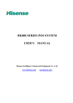
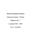
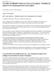
Model: UT-794
4-Port Industrial RS-485/422 PCI-E Multi-Serial Port Card
Ⅰ. Summary
UT-794 industrial PCI converter card is designed to convert PCI signals into RS-422/RS-485
signals. The built-in opto-isolator and state-of-the-art TVS, Transient Voltage Suppressor, are being
used in the system. It is also equipped with a high-speed transient voltage suppressing protector,
which can protect circuit components from damages caused by transient high voltage impacts. The
protector can effectively suppress the lightning and ESD. It also provides 600W of lightening surge
protection for each line, and protection against surge voltage and transient over voltage caused by
any other factors. It also guarantees the high-speed transmission of RS-422/RS-485 interface.
Ⅱ. Feature
Hardware Interface
Connection Type: DR44 female x1
BUS: X1 2.5Gbps PCI Express
Signal RS-422: T/R+、T/R-、RXD+、RXD-、GND
Signal RS-485: Data+ (A)
Data-(B) GND
Transmission Rate: 300bps-921.6Kbps
Data Bit: 5、6、7、8
Stop Bit: 1、1.5、2
Parity Bit: None、Even、odd、Space、Mark
Flow Control: RTS/CTS XON/XOFF
Operating Temperature: -40℃~85℃
Interface Protection:600W surge protection per line for RS-485、RS-422 interface,±15KV ESD
protection
Transmission distance: RS-485/422 communication distance reaches up to 1.2Km
Supporting System: Win2000/XP/Vista/Win7/NT4.0/CE 4.2/5.0/6.0/Vxworks/Linux 2.4.x/2.6.x
The speed of each interface can reaches up to 921.6Kbps and supports 256byteFIFO drivers and
internal soft and hardware flow control. The universal use PCI is compatible with PCI-E.
Ⅲ. Connector and Signal
1、DB9 PIN:RS-485/RS-422 output pin allocation. (Port1-Port4)
Ⅴ. Connection Illustration
Ⅵ. Faults and Ruling Out:
1、Data Communication Failure
A、Check the PCI-E interface
B、Check if RS-485/RS-422 output interface line is correct
C、Check if the power supply light is lit
D、Check if the line terminal is connected properly
E、Check if the receiving indicator is flashing during reception.
F、Check if the sending indicator is flashing during sending.
2、 Data Loss or Mistake
A、Check if the speed and format of the data communication for both equipment terminals
are the same.
Ⅶ. Driver Installation
The system will automatically open the following window when the UT-794 is inserted.
Choose [Install from a list or specific location (Advanced)], then click [Next].
The window opened by system to select an installation path will appear as illustrated
below.Choose [Search for the best driver in these location],then choose [Include the location in the
search], click the [Browser] button and choose a folder on the CD.If you are using Windows
XP,click Win2KXP folder,if not,click corresponding folder,then click [Next].
The system will start the installation after searching for and locating the driver.
The hardware guide will appear in another window. This will install the driver for the
remaining 3 serial ports. Choose [Install from a list or specific location (Advanced)], click [Next]
Repeat these steps to complete driver installation for the remaining 3 serial ports and they will
be ready for use.
After the drivers have been installed, open the equipment manager to see if the device panel
has any virtual COM ports. If the system had not previously installed any serial port drivers, the
system’s default COM ports are COM3、4、5、6.As shown in the image below, all drivers for the
UT-794 have been fully installed.
3
4
5
6