1
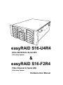
easyRAID S16-U4R4
Ultra 320 SCSI to Serial ATA
Disk Array System
&
easyRAID S16-F2R4
Fibre Channel to Serial ATA
Disk Array System
Hardware User Manual
Table of Contents
Preface.................................................................................................................. iii
Chapter 1 Overview
Features ................................................................................................................ 2
Understanding RAID ............................................................................................. 3
Just a Bunch Of Disks ...................................................................................... 3
RAID Levels ..................................................................................................... 3
Hot Spare Disks ............................................................................................... 6
RAID Combinations .......................................................................................... 6
Summary of RAID Levels ................................................................................. 7
System Requirements ........................................................................................... 8
Operating Environment .................................................................................... 8
VT100 Terminal Settings .................................................................................. 8
Host Interface ................................................................................................... 8
Hard Disks ........................................................................................................ 9
Chapter 2 Basic Configuration
Unpacking ........................................................................................................... 11
Components ........................................................................................................ 12
Front View ...................................................................................................... 12
Disk Tray ........................................................................................................ 13
Rear View ....................................................................................................... 14
Installing Disks .................................................................................................... 15
Making Connections ........................................................................................... 18
Connecting the Host Interface ........................................................................ 18
Connecting the RS-232 Cable ........................................................................ 19
Connecting and Turning on the Power ........................................................... 20
Chapter 3 Maintenance
Replacing a Disk ................................................................................................. 21
Replacing a Power Supply .................................................................................. 22
Replacing a Fan .................................................................................................. 24
Upgrading Memory ............................................................................................. 26
Appendix
Hardware Specifications ..................................................................................... 31
Warnings and Certifications ................................................................................ 33
i
Preface
About this Manual
This manual is designed to make the disk array system as easy to use as possible. Information
contained in this document has been checked for accuracy, but no guarantee is given that the contents is correct. Information and specifications are subject to change without notice.
Copyright Notice
© Copyright 2003
All rights reserved. This disk array system and related documentation are protected by copyright
and are distributed under licenses restricting their use, copying, and distribution. No part of this
documentation may be reproduced in any form by any means without prior written authorization
of the company and its licensors, if any.
Conventions
Caution
This symbol is used to remind users to pay attention to important
descriptions regarding usage and maintenance (repair) or additional
important information related to this disk array system.
Note
This symbol is used to remind users of useful information that can make
procedures such as configuration easier to accomplish.
iii
easyRAID S16 Serial ATA Disk Array Systems
Important Safety Instructions, Care and Handling
Preface –
Before starting, take a few minutes to read this manual.
Read all of these instructions and save this manual for
later reference.
Protect the disk array system from extremely high or low
temperatures. Let the disk array system warm (or cool)
to room temperature before using it.
Important Safety Instructions, Care and Handling
Protect the disk array system from being bumped or
dropped. Do not place the disk array system on an
unstable cart, stand, or table. It may fall, causing serious
damage to the product.
Keep the disk array system away from magnetic forces.
Do not use the disk array system near water.
Keep the disk array system away from dust, sand, or dirt.
Gaps and openings in the cabinet are provided for ventilation. Never block or cover these openings, because
the disk array system may overheat and become unreliable. Don’t place the disk array system on a bed, sofa,
rug, or other similar surface.
Do not place the disk array system near or over a radiator or heat register.
V
Refer to the rating plate for the correct voltage and
ensure that the appliance voltage corresponds to the
supply voltage.
iv
easyRAID S16 Serial ATA Disk Array Systems
The appliance must be grounded. The disk array system
is equipped with a 3-wire grounded type of power cord.
This power cord will only fit into a grounded type of
power outlet.
Never push any kind of object into the disk array system
through cabinet gaps and openings, since they may
touch dangerous voltage points and cause a risk of fire
or electric shock.
Unplug the power cord from the wall outlet before cleaning. Keep the disk array system dry. Do not use liquid
cleaners, aerosol cleaners, or a wet cloth. Use a damp
cloth for cleaning.
Except as specifically explained in this User Manual, do
not attempt to service the disk array system by yourself.
Opening or removing the covers may expose you to
dangerous voltages.
Unplug this product from the wall outlet and refer servicing to qualified service personnel under the following
conditions.
• If the disk array system has been exposed to
water or any liquid.
• If the disk array system has been dropped or the
cabinet damaged.
v
Important Safety Instructions, Care and Handling
Do not place the disk array system where the cord will
be walked on.
Preface –
If an extension cord or a power center is used with the
disk array system, make sure that the total current consumption of all products plugged into the wall outlet
does not exceed the ampere rating.
easyRAID S16 Serial ATA Disk Array Systems
Placement Notes
Preface –
Important Safety Instructions, Care and Handling
• The disk array system LCD panel can be damaged by exposure to
direct sunlight. Limit exposure to subdued or indirect sunlight only.
• The disk array system should be used only in clean environments
that are free from airborne contaminants such as dust, dirt, and
smoke. Excessive moisture or oil particles in the air can also hinder
disk array system performance.
• To reduce the possibility of data errors caused by electromagnetic
interference, locate the disk array system at least five feet away
from electrical appliances and equipment that generates magnetic
fields.
Power Supply Safety Notes
• To avoid electric shocks, do not use an extended power cord or an
outlet that does not match the disk array system plug or leaves the
plug exposed.
• The disk array system has a 3-wire grounded plug. The third pin
connects to ground; do not remove it.
• If the power cord or plug is damaged or worn, unplug it immediately
and contact a qualified service technician for maintenance.
• To avoid fire or electric shocks, do not overload electric power outlets.
vi
1 Overview
The disk array system uses groups of inexpensive disks to provide flexibility when
balancing data availability, access rate, and
capacity management needs.
High data availability is achieved by using
the fault tolerance features of RAID
(Redundant Array of Inexpensive Disks);
hot spare disks with automatic on-line
rebuild; hot swap disks, power supplies, and
fans; independent serial ATA (SATA) disk
controllers; and dual host controllers. Our
confidence in the disk array system is
backed by a three year warranty.
A high data access rate is achieved by combining the individual data rates of serial ATA disks in
a RAID configuration. Serial ATA disks lack some of the features of SCSI disks but are just as
fast when used with a high performance RAID controller. In the disk array system, RAID is controlled by a high performance CPU, which transfers data through dual host interfaces at the maximum possible rate.
Flexible data capacity management is achieved with on-line RAID expansion, RAID capacity
division into slices, and multiple logical RAIDs. Management is performed through front panel,
or RS-232 interfaces.
1
easyRAID S16 Serial ATA Disk Array Systems
Features
1
The main features of the disk array system are listed as follows. Refer to the specifications table
on page 31 for more detailed information.
Overview – Features
•
•
•
•
•
•
•
•
•
•
•
•
•
Operating system independent
Up to eight JBOD, RAID 0, 1, 3, 5, 0+1, 30, or 50 array groups
On-line expansion
Allows division of array groups into slices, each mapped to a LUN
Hot spare disk and automatic on-line rebuild
Up to 16 hot swap serial ATA disks for a total capacity of 3.5 TB (terabytes)
Three hot swap power supplies – if one fails, the others take over without interruption
Two hot swap fans with intelligent speed and temperature management
Sixteen 150 MB/s serial ATA channels
Fast 64-bit RISC CPU based RAID controller with up to 1 GB of cache in an SO-DIMM
Dual Ultra SCSI (ERX16S-U4R4) or fibre channel (ERX16S-F2R4) host interfaces
Audible alarm, disk tray LED, and LCD panel failure indicators
Configuration via the front panel and RS-232 interfaces
2
easyRAID S16 Serial ATA Disk Array Systems
Understanding RAID
Just a Bunch Of Disks (JBOD) consists of two or more disks that can be different sizes. Disk 1 is
completely filled, then disk 2, disk 3, and so on until the final disk is full.
The total capacity of JBOD is the sum of the capacities of each disk. Disks are added until the
desired total capacity is reached.
JBOD is used in the following situations:
• Building useful capacity from disks that are too small to be individually useful
• Making capacity management easier, since the user only sees one logical disk
JBOD doesn’t improve data availability or access rate when compared with a single disk.
RAID Levels
The overall arrangement of disks in RAID is called the RAID level. Read this section to understand RAID levels.
RAID 0
In RAID 0, data is divided into pieces and written to all disks in parallel. This process is called
striping because the pieces of data form a stripe across multiple disks. This improves access rate,
but makes availability lower, since there are more disks and failure of a single disk causes failure
of the array. A RAID 0 array is unsuitable for data that can not easily be reproduced, or for data
that must be available for critical system operation.
RAID 0 consists of two or more disks of equal capacity. The total capacity of RAID 0 is the sum
of the capacities of each disk. Disks are added until the desired total capacity is reached.
3
Overview – Understanding RAID
Just a Bunch Of Disks
1
Read this section to understand how to balance data availability, access rate, and capacity management needs.
easyRAID S16 Serial ATA Disk Array Systems
A RAID 0 array is useful in the following situations:
1
Overview – Understanding RAID
• Storing program image libraries or run-time libraries for rapid loading. A backup exists
because these libraries are usually supplied on read-only media.
• Storing large tables or other structures of read-only data for rapid application access. This
data should be backed up so that it can be recreated in the event of a failure.
• Capturing data from external sources at very high data transfer rates.
A RAID 0 array is not useful in the following situations:
• Applications that make sequential requests for small amounts of data. These applications
spend most of their I/O time waiting for disks to spin, whether or not they use striped
arrays.
• Applications that make synchronous random requests for small amounts of data.
RAID 1
Optional
In RAID 1, data is duplicated on two or more disks to provide high access rate and very high data
availability. This process is called mirroring. If a disk fails, the RAID controller directs all
requests to the surviving members.
A RAID 1 array is useful in the following situations:
• Availability requirements are very high
• High access rate is required
• Cost of storage is a secondary issue
4
easyRAID S16 Serial ATA Disk Array Systems
RAID 3
1
RAID 3 consists of two or more disks used for data and one disk used for fault tolerant data. The
total capacity of RAID 3 is the sum of the capacities of each data disk. Add disks until the desired
capacity is reached, then add one more disk for fault tolerance.
RAID 3 is used by the following applications that request large amounts of data sequentially:
• Processing of graphical or video images
• Processing of CAD/CAM files
RAID 3 has the following characteristics:
• Excellent performance for data transfer intensive applications
• Not well suited for transaction processing or other I/O request intensive applications
5
Overview – Understanding RAID
In RAID 3, data is divided into pieces; the parity of these pieces is calculated; and the pieces are
written to separate disks in parallel with the writing of the parity to a dedicated disk. This process
is called striping with parity. The parity disk stores redundant information about the data on other
disks. If a single disk fails, then the data on the other disks is used to regenerate the data on the
failed disk. Striping delivers a high access rate and parity delivers good data availability. The single parity disk is a bottleneck on sequential writes, since parity must always be written to the single parity disk.
easyRAID S16 Serial ATA Disk Array Systems
RAID 5
1
Overview – Understanding RAID
In RAID 5, data is divided into pieces; the parity of these pieces is calculated; and the pieces and
parity are written to separate disks in parallel. The parity is written to a different disk each time.
Parity provides redundant information about the data on other disks. If a single disk fails, then
the data on the other disks is used to regenerate the data on the failed disk. Striping delivers a
high access rate and parity delivers good data availability. The bottleneck caused by the single
parity disk of RAID 3 is not present in RAID 5, since parity is stored on all disks.
RAID 5 consists of two or more disks used for data and one additional disk used for fault tolerence. The total capacity of RAID 5 is the sum of the capacities of each data disk. Add disks
until the desired capacity is reached, then add one more disk for fault tolerance.
RAID 5 is best used with applications whose data has the following characteristics:
• The data is worth protecting, but not as much as in a RAID 1 configuration
• High read data rates
• Small proportion of writes to reads
Hot Spare Disks
A hot spare disk is a standby disk that is not used for data storage unless a RAID member fails. If
a disk failure occurs, the failed RAID member is replaced by the hot spare disk without user
intervention. This improves data availability, since the RAID is able to tolerate more disk failures
with a hot spare disk.
RAID Combinations
RAID levels may be combined in the following hierarchies:
• RAID 0+1 is a RAID 1 consisting of RAID 0 members
• RAID 30 is a RAID 0 consisting of RAID 3 members
• RAID 50 is a RAID 0 consisting of RAID 5 members
6
easyRAID S16 Serial ATA Disk Array Systems
Summary of RAID Levels
The following table summarizes the performance characteristics of each RAID level. A high
availability or access rate number indicates high availability or quick access rate.
1
Availability
Access
Rate
Capacity
Utilization
JBOD
1
1
100%
Data is distributed by filling each
disk in turn.
RAID 0
1
5
100%
Data is divided into pieces and
written to all disks in parallel.
RAID 1
5
2
50%
Data is duplicated on both disks.
RAID 3
3
3
Between 67%
for 3 disks to
94% for 16
disks
Data is divided into pieces; the
parity of these pieces is calculated; and the pieces are written
to separate disks in parallel with
the writing of the parity to a dedicated disk.
RAID 5
3
3.5
Between 67%
for 3 disks to
94% for 16
disks
Data is divided into pieces; the
parity of these pieces is calculated; and the pieces and parity
are written to separate disks in
parallel. The parity is written to a
different disk each time.
RAID 0+1
4.5
5
50%
RAID 0+1 is a RAID 1 consisting
of RAID 0 members.
RAID 30
4
4
Between 67%
for 6 disks to
88% for 16
disks
RAID 30 is a RAID 0 consisting
of RAID 3 members.
RAID 50
4
4.5
Between 67%
for 6 disks to
88% for 16
disks
RAID 50 is a RAID 0 consisting
of RAID 5 members.
7
Description
Overview – Understanding RAID
Array
Group
easyRAID S16 Serial ATA Disk Array Systems
System Requirements
Ensure that the following requirements are met before installing the disk array system.
1
Overview – System Requirements
Operating Environment
•
•
•
•
•
15 cm (6 inches) of space around the disk array system for proper ventilation
ambient temperature of 5°C to 40°C (40°F to 104°F)
ambient non-condensing relative humidity of 10% to 85%
dust, smoke, and oil free environment
no large magnetic fields, such as those generated by a high voltage power cables and
motors, etc.
• no direct sunlight
• a flat, stable surface capable of supporting the disk array system
VT100 Terminal Settings
Refer to the following table for a summary of VT100 terminal settings required to communicate
with the disk array system. Refer to your system manual for instructions on setting up the VT100
terminal settings.
Item
Required Setting
Connection
Serial Port (COM1 or COM2)
Protocol
RS232 (Asynchronous)
Cabling
Null Modem cable
Baud Rate
115, 200
Data Bits
8
Stop Bit
1
Parity
None
Host Interface
The disk array system has either dual SCSI interfaces or dual fibre channel interfaces. Refer to
the following sections to understand host interface system requirements.
8
easyRAID S16 Serial ATA Disk Array Systems
Small Computer Systems Interface
The ERX16S-U4R4 has dual Ultra320 SCSI interfaces that are compatible with previous SCSI
standards. Refer to the following table to understand SCSI bus requirements.
1
Subtract the internal cable length (60 cm) from the maximum SCSI bus
length to calculate the maximum external SCSI cable length.
SCSI
Standard
Maximum
SCSI Bus Length
in Meters
Data Rate
in Megabytes
per Second
Maximum
Number of Devices
Ultra320
12
320
15
Ultra160
12
160
15
Ultra2
12
80
15
Ultra Wide
1.5
40
7
Fast Wide
3
20
15
Ultra
1.5
20
7
Fibre Channel Interface
The ERX16S-F2R4 has dual 2 Gbit fibre channel interfaces with SFP connectors for linkage to a
fibre channel switch or host computer interface card. With the correct SFP transceiver and optical cable, the following transmission distances can be achieved.
Component
Optical
SFP Transceiver
LC Optical
Cable
Short Wave
Long Wave
Maximum Cable Length
50m
10 Km
Hard Disks
Supply the number of serial ATA disks needed for your application. Refer to “Understanding
RAID” on page 3 to determine the number of disks needed.
9
Overview – System Requirements
Note
2 Basic Configuration
This chapter describes disk array system connections and disk installation.
Unpacking
Contact your supplier if any of the following items are missing or damaged.
Caution
The disk array system is heavy. Be careful when lifting and moving it.
Active Terminator
(ERX16S-U4R4
Disk Array System
Disk Tray Keys
Ultra320 SCSI Cable
(ERX16S-U4R4 Only)
RS-232 Cable
Power Cables
User Manual
11
easyRAID S16 Serial ATA Disk Array Systems
Components
2
Basic Configuration – Components
Front View
18 19
20 21
Power
ESC
17
P/S Fail
Enter Access
1
11
Power
ESC
P/S Fail
Enter Access
2
22
23
24
12
3
13
4
14
5
15
6
16
7 8 9 10
No.
1-16
Name
Description
Disk trays 1 to 16
Removable hot swap disk trays.
17
LCD panel
Displays warning, operating, and configuration
information.
18
Down function button
Moves down in the LCD menus.
19
Up function button
Moves up in the LCD menus.
20
Escape function button
Returns to the previous LCD menu without making
changes.
21
Enter function button
Selects a menu item or confirms a choice or entry.
22
Power-on indicator (green)
Indicates the disk array system power is on.
23
Power supply fail indicator (red)
Indicates a failed power supply.
Host computer access indicator
Indicates data transfer between the disk array system and the host computer.
24
12
easyRAID S16 Serial ATA Disk Array Systems
Disk Tray
1
1
2
Top
Basic Configuration – Components
Left
Right
Front
4
5
2
3
No.
Name
Description
1
Disk mounting holes
Allows the disk be mounted on the disk tray with the
screws included with the disk.
2
Tray lock
Prevents unauthorized removal of a disk tray. Open
with the included disk tray lock key.
3
Tray handle
Releases the disk tray.
4
Power/Error indicator LED
Indicates normal operation of the disk when green, or
an error or failure of the disk when red.
5
Access indicator LED
Indicates that the disk is being accessed when orange.
13
easyRAID S16 Serial ATA Disk Array Systems
Rear View
1
2
3
4
5
6
7
8
9 10
2
Basic Configuration – Components
11
13
14
12
No.
16
15
Name
Description
Connects to a VT100 terminal or equivalent.
10
RS-232 Port
Ethernet Port
ERX16S-F2R4 Host Port 1
(Primary fibre channel)
ERX16S-F2R4 Host Port 2
(Secondary fibre channel)
ERX16S-U4R4 Host Port 2
(Secondary SCSI channel)
ERX16S-U4R4 Host Port 1
(Primary SCSI channel)
Main Power Switch
Power Supply 1
Power Supply 2
Power Supply 3
11
Fan 1
Removable redundant fan 1.
12
Fan thumbscrews
Allows the fan to be removed.
13
Fan 2
Removable redundant fan 2.
14
Hot Swap Power Supply Release
AC Power In
Power Supply On Indicator
Allows the power supplies to be removed.
1
2
3
4
5
6
7
8
9
15
16
Used for browser-based configuration.
Connects to the host server.
(Found only on the ERX16S-F2R4)
Connects to the host server.
(Found only on the ERX16S-F2R4)
Connects to the host server.
(Found only on the ERX16S-U4R4)
Connects to the host server.
(Found only on the ERX16S-U4R4)
Turns the main power on or off.
Removable redundant power supply 1.
Removable redundant power supply 2.
Removable redundant power supply 3.
Connects to a 110-240 VAC power source.
Indicates normal operation of the power supply
when green, or standby when red.
14
easyRAID S16 Serial ATA Disk Array Systems
Installing Disks
Basic Configuration – Installing Disks
1 Unlock the disk tray.
2
This section describes how to install disks in the disk array system. Read “Understanding RAID”
on page 3 to decide how many disks are required.
2 Pull the disk tray handle to the open position.
3 Pull the disk tray out.
15
easyRAID S16 Serial ATA Disk Array Systems
4 Insert the disk into the disk tray. The disk should face up with the connectors directed
toward the open rear of the tray.
2
Basic Configuration – Installing Disks
5 Align the rear of the disk with the rear of the disk tray.
6 Attach the disk to the disk tray with the screws that came with the disk.
7 Insert the disk tray back into the empty slot.
16
easyRAID S16 Serial ATA Disk Array Systems
8 Push the disk tray handle closed.
2
Basic Configuration – Installing Disks
9 Lock the disk tray.
10 Repeat steps 1 to 9 until all of the required disks have been installed.
17
easyRAID S16 Serial ATA Disk Array Systems
Making Connections
2
After the required number of disks have been installed, external connections to the disk array
system must be made. This section describes how to make all of the necessary connections.
Basic Configuration – Making Connections
Connecting the Host Interface
The disk array system has either dual SCSI interfaces or dual fibre channel interfaces. Refer to
the following sections to make host interface connections.
Small Computer Systems Interface
The ERX16S-U4R4 has dual Ultra320 SCSI interfaces. Follow these instructions to make connections.
1 Connect the active SCSI terminator (A) to the bottom connector of the ERX16S-U4R4
host port 1 (primary SCSI channel) at the rear of the disk array system.
A
B
2 Connect the Ultra320 SCSI cable (B) to the top connector of the ERX16S-U4R4 host
port 1 (primary SCSI channel) at the rear of the disk array system.
18
easyRAID S16 Serial ATA Disk Array Systems
Fibre Channel Interface
B
Connecting the RS-232 Cable
Connect the supplied RS-232 cable to the RS-232 port at the rear of the unit.
19
Basic Configuration – Making Connections
A
2
The ERX16S-F2R4 has dual 2 Gbit fibre channel interfaces. Each interface can be used with optical or copper transceivers and cables. Follow these instructions to make optical connections.
1 Insert the LC Optical SFP transceiver (A) in to the ERX16S-F2R4 host port 1 (primary
fibre channel) at the rear of the disk array system.
2 Connect the optical cable (B) to the LC Optical SFP transceiver (A).
easyRAID S16 Serial ATA Disk Array Systems
Connecting and Turning on the Power
1 Connect a power cable (A) to the power supply 1 connector at the rear of the unit.
The power supply on indicator LED glows red.
2
Basic Configuration – Making Connections
A
B
2 Connect the second and third power cables to the power supply 2 and 3 connectors at the
rear of the unit. Each power supply on indicator LED glows red when the second and
third power supplies are connected.
Note
The system is equipped with auto switching power supplies that
can run on 100 to 240 VAC.
3 Press the disk array system main power switch (B) to the ON position. All power supply
on indicator LEDs glow green and disk array system automatically begins the self-test
sequence.
20
3 Maintenance
Replacing a Disk
A disk failure is indicated when the Power/Error LED at the front of the drive tray turns red and
the audible alert sounds.
Note
Turn off the audible alert by pressing the Up and Down
tons on the front panel twice simultaneously.
function but-
The LCD screen shows the failure with the symbol “R” or “W”. “R” indicates a disk failure or
error, and “W” indicates that there are too many bad sectors on the disk.
Example:
• Disks 1 to 9 are members of array group 1.
• Disks 10 to 14 are members of array group 2.
• Disk 15 has too many bad sectors.
• Disk 16 has an error or a fault.
1111 11111 22222 WR
Disks are hot swappable, which means that they can be inserted and removed while the disk array
system is powered on and operating. Follow these instructions to replace a failed disk.
1 Unlock the disk tray.
2 Pull the disk tray handle to the open position, then pull the disk tray out.
3 Remove the screws from the failed disk, then remove the failed disk from the disk tray.
4 Insert the new disk into the disk tray. The disk must be face up with the connec-
tors directed toward the open rear of the tray.
Note
The new disk must have the same or a greater capacity than the
faulty disk that was removed. If the disk capacity is smaller, the
audible alert sounds and the auto-rebuild operation doesn’t start.
For best performance, it is recommended that the new disk be
identical to the failed disk.
5
6
7
8
Align the rear of the disk with the rear of the disk tray.
Attach the disk to the disk tray with the screws that came with the disk.
Insert the disk tray back into the empty slot, then close the tray handle.
Lock the disk tray. The disk array automatically begins rebuilding the RAID.
21
easyRAID S16 Serial ATA Disk Array Systems
Replacing a Power Supply
3
Maintenance – Replacing a Power Supply
The disk array system is equipped with a Power Supply Fail Indicator LED at the front of the unit
that turns red when one of the power supplies fails. The message “Power x failure” also appears
on the LCD panel, where x refers to power supply 1, 2, or 3, and an audible alert sounds.
Note
Turn off the audible alert by pressing the Up and Down
tons on the front panel twice simultaneously.
function but-
Power supplies are hot swappable, which means that they can be inserted and removed while the
disk array is powered on and operating. Follow these instructions to replace a failed power supply.
1 Identify the power supply that has failed.
Power Supply 1
Power Supply 2
Power Supply 3
2 Unplug the power cable connected to the failed power supply unit.
22
easyRAID S16 Serial ATA Disk Array Systems
3 Push the power supply release switch (A) and pull the power supply handle (B) out at
the same time.
3
1
B
2
3
4 Remove the power supply unit.
1
2
3
5 Insert a new power supply unit in the empty power supply unit slot. The power supply
automatically locks into position when fully inserted.
1
2
3
6 Reconnect the power cable. The Power supply On indicator LED glows green.
23
Maintenance – Replacing a Power Supply
A
easyRAID S16 Serial ATA Disk Array Systems
Replacing a Fan
3
A fan failure is indicated by the LCD panel message “Fan x failure”, where x refers to Fan 1 or
Fan 2. An audible alert also sounds.
Maintenance – Replacing a Fan
Note
Turn off the audible alert by pressing the Up and Down
tons on the front panel twice simultaneously.
function but-
Fans are hot swappable, which means that they can be inserted and removed while the disk array
is powered on and operating. Follow these instructions to replace a failed fan.
1 Identify the fan that has failed.
Fan 1
Fan 2
2 Loosen the fan enclosure thumbscrew, then open the fan enclosure to a 90º angle.
Caution
High speed rotating fan blades can cause injury. Wait until the fan has
stopped completely before removing it.
24
easyRAID S16 Serial ATA Disk Array Systems
3 Remove the fan from the fan enclosure, then insert a new fan in the fan enclosure.
3
Maintenance – Replacing a Fan
Caution
The fan will begin rotating immediately after it is plugged in. Keep your
fingers away from the blades.
4 Close the fan enclosure, then tighten the fan enclosure thumbscrew.
25
easyRAID S16 Serial ATA Disk Array Systems
Upgrading Memory
3
The disk array system takes a single 200 pin PC200 DDR SDRAM SO-DIMM with a maximum
capacity of 1 GB. Follow these instructions to upgrade the memory.
Maintenance – Upgrading Memory
1 Remove the six screws from the ERX16S-U4R4 top cover as illustrated.
2 Slide the top cover toward the rear of the unit, then lift the cover.
26
easyRAID S16 Serial ATA Disk Array Systems
3 Carefully lift the daughterboard from the array group controller.
3
Daughterboard
27
Maintenance – Upgrading Memory
Array group controller
easyRAID S16 Serial ATA Disk Array Systems
4 Pull the DIMM retaining clips away from the DIMM; the DIMM springs out of the
socket. Remove the DIMM.
3
Maintenance – Upgrading Memory
5 Gently push the new DIMM into the socket at 45 degrees, then push the corners of the
DIMM down. The DIMM is secured by the DIMM socket retaining clips.
Note
The DIMM module will fit in only one direction. Do not force the
DIMM into place.
28
easyRAID S16 Serial ATA Disk Array Systems
6 Replace the daughterboard on the array group controller, taking care to align the connectors.
3
Daughterboard
29
Maintenance – Upgrading Memory
Array group controller
easyRAID S16 Serial ATA Disk Array Systems
7 Place the top cover on the disk array system, then slide the top forward into the closed
position.
3
Maintenance – Upgrading Memory
8 Replace the six screws to fix the top cover on the disk array system chassis.
30
Appendix
Hardware Specifications
Item
Specification
Host Interface
SCSI Ultra320 (ERX16S-U4R4) or 2 Gbit Fibre Channel (ERX16S-F2R4)
Disk Interface
16 x Serial ATA (SATA), 150 MB/s
Dimensions
175 mm (H) x 483 mm (W) x 583 mm (D)
Weight
21 Kg without disks
RAID
Functions
•
•
•
•
Raid levels: JBOD, 0, 1, 0+1, 3, 5, 30 or 50
Hot spare support
Disk hot swapping with automatic online rebuilding
Multiple RAID (max. 8)
Disk Array
Functions
•
•
•
•
•
•
•
O/S independent and transparent
Maximum fault tolerant capacity > 3.5 TB
64 MB ~ 1 GB DDR SDRAM
LCD panel operation indicator
Audible alarm/disable alarm
Optional battery backup for disk array status
LED indicator on disk failures
Connectors
• 4 x Ultra320 SCSI ports (ERX16S-U4R4) or
2 x 2 Gbit Fibre Channel ports (ERX16S-F2R4)
• 1 x RS-232 Serial port (115200, n, 8, 1)
• 1 x RJ-45 Ethernet port (10 Mbps)
Power Supply
•
•
•
•
•
•
•
•
•
•
Warranty
3 year warranty
EMI
CE class B, FCC class B, C-Tick class B and BSMI class B
Safety
UL, cUL and CB
600W (2+1) redundant
90 - 264 VAC, 47-63 Hz, +/- 10%
Over voltage, current, power, and short circuit protection
LED indicates power status
Operating temperature: 0°C ~ 50°C
Operating humidity: 20 ~ 90%
Output: +5V, +3.3V, +12V
Harmonic: meets EN6100-3-2 standard
EMI/RFI: CE, FCC class B and CISPR class B
Safety: UL, cUL, CB, TUV
31
easyRAID S16 Serial ATA Disk Array Systems
Item
Specification
Controller
Appendix –
CPU
Intel i80321 64-bit RISC microprocessor
Disk Interface
Serial ATA 1
Disk Channels
16 channels (up to 32 channels by using a
daughter board)
Disk Interface Chipset
Marvell MV88SX8050
Hardware Specifications
Memory Type
PC200 DDR 200-pin SO-DIMM
Memory Sockets
1
Memory Size
Up to 1 GB
LCD Interface
One LCD panel, 2 lines by 16 characters
Button Interface
Up, Down, ESC, Enter and Reset
Battery Backup Interface
Yes
Daughter Board Interface
PCI-X 64-bit, 66/133MHz
Backplane Interface
(connector)
Compact-PCI
Disk Channel Support
16 channels
Disk Channel Support
16 disks
Disk Connector Type
Serial ATA
Sequence Disk Power On
Select by jumper
(H/W: power on all disks,
S/W: 4 disks at 2 ms intervals)
Temperature Sensors
13
Power Connector Type
ATX x 2
Fan Connector Type
1 x 3-pin with housing, 2.54 mm pitch
(1 red, 1 white)
Backplane
32
easyRAID S16 Serial ATA Disk Array Systems
Item
Cooling Fans
Specification
Fan 2 rpm
Under 25°C
1000
1000
26°C ~ 40°C
1500
1500
41°C ~ 50°C
2100
2100
Over 51°C
3100
3100
Fan 1 Failure
Failed
3100
Fan 2 Failure
3100
Failed
Any Power Module Failure
1000
1000
Warnings and Certifications
Federal Communications Commission (FCC)
This FCC certification applies in the U.S. and Canada. This equipment has been tested and found
to comply with the limits for a Class B digital device, pursuant to Part 15 of the FCC Rules.
These limits are designed to provide reasonable protection against harmful interference when the
equipment is operated in a residential installation. This equipment generates, uses, and can radiate radio frequency energy and, if not installed and used in accordance with this user's guide,
may cause harmful interference to radio communications. However, there is no guarantee that
interference will not occur in a particular installation. If this equipment does cause harmful interference to radio or television reception, which can be determined by turning the equipment off
and on, the user is encouraged to try to correct the interference by one or more of the following
measures:
• Reorient or relocate the receiving antenna.
• Increase the separation between the equipment and receiver.
• Connect the equipment into an outlet on a circuit different from that to which the receiver
is connected.
• Consult the dealer or an experienced radio/TV technician for help.
33
Warnings and Certifications
Fan 1 rpm
Appendix –
Temperature