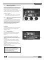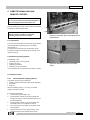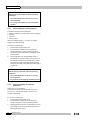
1
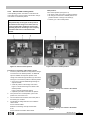
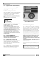
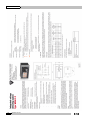
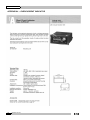
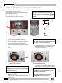
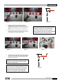
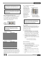
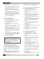
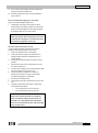
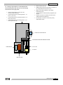
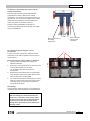
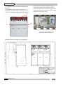
Xiria UK-ENA 6. The panel requires to be returned to the neutral position on completion of the operations. Proceed as follows: remove the back-up earthing equipment when this is mounted; connect the cable connection plugs according to the supplier's instructions; close the cable access door; remove any padlocks fitted; open the switch. check the position indicator. TIP The above switching operations are summarised for experienced users in tables shown in section 4.5. 4.3 Interlocks The Xiria unit is equipped as standard with built-in interlocks to prevent accidental switching operations. LIFE HAZARD Undesirable switching operations could result in the following: • danger to personnel (operating and service personnel); • failure of power supply; • damage to the unit. WARNING If a (switching) action cannot be achieved with normal operating force: • • Check against section 4 whether the action to be carried out is permissible; Notify Eaton if the action is permissible according to the switching tables but cannot be accomplished with normal operating force. 4.3.1 Electrical interlocks The opening of the circuit-breaker via the integrated protection relay is only possible in the operating position, not in the earthed position. Remote tripping is only possible in the operating position. Remote closing is only possible in the operating position. 4.3.2 Mechanical interlocks Interlock to prevent cable access from being opened if cable is not earthed. Note: Once the cable access door has been opened, the panel can be switched off to carry out cable tests; this interrupts the cable-earth link. Interlock to prevent operation of the change-over switch when the circuit-breaker or load-break switch is active. In order to prevent reflex attempts to switch off a shortcircuit with a load-break switch after switching on, the opening button is equipped with an anti-reflex flap (1). This flap is held in place with an extra locking device (2) connected to the switch control point flap to achieve the correct anti-reflex time. This device must never be removed. To prevent operation when this is not allowed, the opening button (3) and the switch control point (4) and the change-over switch control point (5) are each equipped with locking flaps. These locking flaps can be padlocked according to user company procedures which are not described in this manual. NOTE When these padlocks are installed, the panel can still be operated with the remote control (if installed) and the circuit-breaker still can be switched off by the protection relay when this panel is in operating position. WARNING After any temporary absence, check that the necessary interlocks and eventually mounted back-up earths are still in place. 22 994.607 G01 03