1
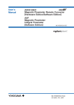
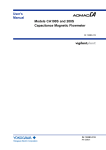
4. WIRING
Finished diameter: 10.5 mm (0.413")
Maximum length: 100 m (330 ft)
Maximum temperature: 80°C (176°F)
NOTE
Conductors A and B carry the signal from the
electrodes, and C is at the potential of the liquid
(signal common). Shields SA and SB are kept
at the same potentials as the individual electrodes (these are actively driven shields.) This is
done to reduce the effect of the distributed
capacitance of the cable at long cable length.
Note that, since the signals from the individual
electrodes are impedance converted inside the
converter, errors will result if they come in
contact with any other component. Great care
must be taken in the cable end treatment.
IMPORTANT
If the cable is longer than required, cut off any
extra length rather than coiling it up, and terminate the conductors as shown in Figure 4.2.2.
Avoid using junction terminal boards to extend
the cable length, as this will interrupt the shielding.
B
C
90 (3.54)
90 (3.54)
60 (2.36)
C
70 (2.76)
Black
Red
20 (0.8)
150+5
(5.9)
8 (0.3) max.
L (Specified Dimensions)
Outer Diameter: 6.5 to 12 mm in diameter (10.5 or
11.5 mm for waterproof gland /EG, /EU) (6.5 to 12
mm for waterproof gland /EP)
Nominal Cross Section (Single wire): 0.5 to 2.5 mm2
Nominal Cross Section (Stranded wire): 0.5 to 1.5 mm2
On the
flowtube
side
10.5 (0.4)
(5.9)
8(0.3) max.
On the
converter
side
White
Red
Black
150+5
White
(2) Excitation Cable/Power Cable/Output
Cable
Use polyvinyl chloride insulated and sheathed control
cables (JIS C 3401) or polyvinyl chloride insulated and
sheathed portable power cables (JIS C 3312) or the
equivalent.
55 (2.17)
A
SB
50 (1.97)
B
A
SA
25 (0.98)
Unit : mm
(approx. inch)
In case of power cable, Green/Yellow covered conductor shall be used only for connection to PROTECTIVE
CONDUCTOR TERMINALS. Conform to IEC227,
IEC245 or equivalent national authorization.
AXFC
F0402.EPS
Figure 4.2.2 Treatment of Dedicated Signal Cables
Unit : mm
(approx. inch)
CAUTION
100 (3.94)
On the converter side
EX2
EX2
EX1
EX1
Crimp Terminal
• As crimp terminals A, B, SA, SB and C have
their own electrical potentials, securely insulate
them so as not to come in contact with one
another.
• To prevent a shield from coming in contact with
another shield or the case, cover each shield
with a vinyl tube or wrap it in vinyl tape.
100 (3.94)
On the flowtube side
F0403.EPS
Figure 4.2.3 End Treatment of Excitation Cable
4-2
IM 01E20C02-01E