Download RZB_CC16C_ZBK User Manual
Transcript
User
Powerful Processors – Easy to Use™
R8C/Tiny BLDC
Motor Control
Evaluation Kit
(YMCRPR8C25)
User’s Manual
Rev. 1.1
March 2008
www.renesas.com
Table of Contents
Limited Guarantee and Support ................................................................................................................... 4
1.0 Introduction ............................................................................................................................................. 5
2.0 Kit Contents ............................................................................................................................................ 5
2.1. YMCRPR8C25 Kit Item List............................................................................................................... 5
2.1.1. CD-ROM...................................................................................................................................... 6
3.0 System Overview.................................................................................................................................... 6
3.1. Host Computer Requirements ........................................................................................................... 6
3.2. YMCRPR8C25 Board ........................................................................................................................ 6
3.3. Driver and Support Software ............................................................................................................. 6
3.4. Development Tools............................................................................................................................ 6
3.4.1. E8a On-Chip Debug Emulator .................................................................................................... 6
3.4.2. HEW (High-performance Embedded Workshop)........................................................................ 7
3.4.3. M16C Evaluation Version C Compiler......................................................................................... 7
3.4.4. FDT.............................................................................................................................................. 7
3.4.5. Renesas AutoUpdate .................................................................................................................. 7
3.4.6. Documentation, Sample Projects and Project Generators ......................................................... 7
3.4.7. Software Build Process Overview ............................................................................................... 8
3.4.8. Using the evaluation version (64K) of the M16C compiler.......................................................... 8
4.0 Hardware ................................................................................................................................................ 9
4.1. YMCRPR8C25 System Overview ..................................................................................................... 9
4.2. YMCRPR8C25 System Block Diagram ........................................................................................... 10
4.3. The YMCRPR8C25 System Component Descriptions.................................................................... 10
4.3.1. YMCRPR8C25 Board................................................................................................................ 10
4.3.1.1. Jumper Settings .................................................................................................................... 11
4.3.2. Emerson Motor.......................................................................................................................... 11
4.3.3. Power Supply ............................................................................................................................ 11
4.4. R8C/25 Group of MCUs .................................................................................................................. 11
5.0 Motor Control Demo and Support Software ......................................................................................... 12
5.1. Overview.......................................................................................................................................... 12
5.2. Motor Control Demos....................................................................................................................... 12
5.2.1. HALL Sensor Based BLDC Demo ............................................................................................ 12
5.2.2. BEMF (Sensor-less) BLDC Demo............................................................................................. 12
5.3. Sample Code ................................................................................................................................... 12
5.4. Windows GUI YMCRPR8C25 Control Program - LEM ................................................................... 12
5.4.1. OVERVIEW ............................................................................................................................... 12
5.4.2. Running Motor........................................................................................................................... 13
5.4.3. Plotting Data.............................................................................................................................. 13
6.0 System Details...................................................................................................................................... 14
6.1. Hardware Specifications.................................................................................................................. 14
6.2. Power Supply Requirements ........................................................................................................... 14
6.3. Operating Environment.................................................................................................................... 15
Appendix A. Reference Documents ........................................................................................................... 16
A.1 Table - Renesas Documents............................................................................................................ 16
A.2 Table - Other Documents................................................................................................................. 16
Appendix B. Hardware Notes ..................................................................................................................... 17
B.1 Over-Current Circuit ......................................................................................................................... 17
B.2 Back-EMF Detect Circuit .................................................................................................................. 18
B.3 Temperature Sensor ........................................................................................................................ 18
Appendix C. PCB Component Layout ........................................................................................................ 19
C.1 Component Placement - Top ........................................................................................................... 19
C.2 Component Placement - Bottom...................................................................................................... 20
Appendix D. Troubleshooting ..................................................................................................................... 21
YMCRPR8C25 User’s Manual Rev 1.1
2 / 21
March 2008
D.1 Serial Communications .................................................................................................................... 21
D.1.1 Setting the COM Port Number................................................................................................... 21
D.1.2 USB COM Ports......................................................................................................................... 21
D.1.3 LEM Serial Errors ...................................................................................................................... 21
D.2 LEM Hangs ...................................................................................................................................... 21
YMCRPR8C25 User’s Manual Rev 1.1
3/ 21
March 2008
Limited Guarantee and Support
Renesas Technology America, Inc. warrants the YMCRPR8C25 kit to be free from component or
assembly defects for a period of 90 days from the date of purchase. Settlement is limited to repair or
replacement of the product only. Renesas Technology America, Inc. does not assume any liability arising
out of the application or use of any product, circuit or procedure described herein. No other liability or
warranty applies, expressed or implied. Software warranty is limited to replacement of the CD only. While
every attempt has been made to ensure accurate documentation, Renesas Technology America, Inc.,
cannot be held responsible for errors or omissions, and reserves the right to make changes without prior
notice.
YMCRPR8C25 User’s Manual Rev 1.1
4/ 21
March 2008
1.0 Introduction
The YMCRPR8C25 kit is a low-cost Evaluation Kit for evaluating the R8C/25 MCU for use in 3 phase
BLDC motor applications. Renesas firmware is included for evaluating motor drive capabilities of the R8C
family of processors.
The kit comes with a complete software development tool chain for Renesas MCUs, including the Highperformance Embedded Workshop (HEW), which includes an Integrated Development Environment (IDE),
Graphical User Interface (GUI), the M16C C-compiler, assembler and linker.
2.0 Kit Contents
This section describes the contents of the YMCRPR8C25 product package. When unpacking your
YMCRPR8C25, please check to see that all items listed below are included.
2.1. YMCRPR8C25 Kit Item List
Table 2-1 lists the items included in the YMCRPR8C25.
Table 2-1 YMCRPR8C25 Item List
Item Name
YMCRPR8C25 PC board
Motor
Power Supply
Line Cord
4 Conductor Motor Wire Harness
5 Conductor Hall Sensor Harness
E8a
USB Cable
14 Pin Ribbon Cable
9 pin RS232 serial cable
3 pin Phoenix Connector
Fuse, 5A
YMCRPR8C25 Quick Start Guide
YMCRPR8C25 Kit Packing List
YMCRPR8C25 CD-ROM
Quantity
1
1
1
1
1
1
1
1
1
1
1
1
1
1
1
YMCRPR8C25 User’s Manual Rev 1.1
Remarks
R8C/25 MCU mounted on the board
Emerson/HURST 24V BLDC Motor
24VDC, 5A power supply.
“figure 8” to AC plug
White Molex to green 4 pos. Phoenix screw connector
Black inline to green 5 pos. Phoenix screw connector
On-chip Debugging Emulator
E8A > PC Connection
E8A > YMCRPR8C25 Connection
for serial data, YMCRPR8C25 > PC Connection
For use with Bench-top Power Supply
Spare fuse
Auto-install program
HEW (IDE & debugger)
Motor Evaluation Code
M16C C-compiler, assembler, and linker
FDT (Flash Development Tool)
Manuals
Tutorials
Sample programs
5/ 21
March 2008
2.1.1. CD-ROM
The CD-ROM contains the electronic manuals and software necessary for developing programs. Insert
the enclosed CD into your computer; the installer should auto-start. The installer program will create the
C:\Workspace folder on your PC. HEW is installed in the C:\Program Files\Renesas folder by
default.
3.0 System Overview
The following hardware and software products are required to use the YMCRPR8C25 Kit.
•
•
•
•
•
•
•
Host Computer (supplied by user)
YMCRPR8C25 board.
24V BDLC Motor
AC Adapter, 24VDC 5A, center positive
9-pin Serial cable
Software Tools (HEW IDE, FDT, Compiler/Linker) installed on host computer
E8a On-Chip Debugging Emulator (supplied with kit)
3.1. Host Computer Requirements
The minimum requirement to be able to use the software that comes with the YMCRPR8C25 kit is a PC
with a serial port and Microsoft Windows 2000, or XP. For debugging with the optional (user supplied)
E8a in-chip debugging emulator, the PC also needs a USB port.
3.2. YMCRPR8C25 Board
The YMCRPR8C25 board consists of the main board and a 2x8 character based LCD pre-assembled
together. The microcontrollers flash is factory programmed with the Hall Based Application (also included
on the CD) so you can drive the motor right out of the box without loading code.
3.3. Driver and Support Software
The YMCRPR8C25 includes sample drivers for the peripherals used as part of the Project. These provide
working examples for use in driving motors. For details, see Chapter 5.0.
3.4. Development Tools
The installer program installs the development tools. For details on installation, see the QuickStart Guide.
A brief description of all the included tools follows. Please refer to the individual tool manuals for detailed
information.
3.4.1. E8a On-Chip Debug Emulator
The E8a is an On-Chip Debug Emulator for downloading, executing, and debugging code. It connects to
the PC via a USB cable and to the motor control board via a 14-pin ribbon cable. The E8a combined with
the included software development tools provides a complete evaluation and development environment
for the motor control platform.
YMCRPR8C25 User’s Manual Rev 1.1
6/ 21
March 2008
3.4.2. HEW (High-performance Embedded Workshop)
HEW provides a Graphical User Interface (GUI) that integrates the software development tools and
includes the C-compiler, assembler, linker, debuggers and editor. E8a debugger components are
included with this install of HEW.
3.4.3. M16C Evaluation Version C Compiler
The evaluation version of the M16C C-compiler provides the same functionality as the commercial version
except that link size will be restricted to 64 Kbytes after 60 days from when you begin using the compiler.
Contact your local sales representative if you wish to purchase a full license.
3.4.4. FDT
FDT is a Windows based application that can be used to program the flash on R8C/25 MCU’s via a COM
port on your PC or through a debugger. FDT (Flash Development Toolkit) is installed by default as part
of HEW. For using this kit, we program the R8C/25 chip with the E8a debugger within HEW, but FDT is a
handy utility for other situations, such as self-programming through the UART, or with external flash chips.
3.4.5. Renesas AutoUpdate
Included with HEW 4.0 and later is the Renesas AutoUpdate utility. This utility can be configured to
search our website automatically for updates of the Renesas tools installed on your PC. See the HEW
User’s Manual on how to use this feature.
3.4.6. Documentation, Sample Projects and Project Generators
The YMCRPR8C25 includes a full set of user documentation and project generators (a project generator
is a template to create a project.). After installing the CD, documentation can be browsed by using the
“Manual Navigator” from the Start menu (Start > (All) Programs > Renesas > High-performance
Embedded Workshop > Manual Navigator).
All the sample code is contained within the project generator “YMCRPR8C25”. By using the project
generators, the user can name the workspace and project and gives flexibility on where the files are
copied onto the PC.
Within HEW, start a new project workspace, and select YMCRPR8C25 for Project Type. See the Quick
Start Guide for detailed steps to creating a project with project generators.
New Project Workspace Wizard
YMCRPR8C25 User’s Manual Rev 1.1
All YMCRPR8C25 Sample Projects Can Be
Accessed From This Window
7/ 21
March 2008
The download modules for the YMCRPR8C25 demos are included under Sample Code in the
“YMCRPR8C25” project generator.
3.4.7. Software Build Process Overview
The YMCRPR8C25 kit allows the user to write or modify the provided code to evaluate the R8C/25 Motor
Control solution. Code can be compiled and downloaded to the MCU. Debugging can be accomplished
with E8a On-chip debugging Emulator. The figure below illustrates the steps required to create a working
application on the YMCRPR8C25 hardware.
Figure 6.1: Steps to Create a Working YMCRPR8C25 Application
3.4.8. Using the evaluation version (64K) of the M16C compiler
The kit includes a free evaluation version of the compiler. After 60 days, the compiler is restricted to
compiling projects (code and data) to 64K bytes. The MCRP25 uses the R8C/25 which has 64k bytes,
so any project for this device will work with the evaluation version.
YMCRPR8C25 User’s Manual Rev 1.1
8/ 21
March 2008
4.0 Hardware
4.1. YMCRPR8C25 System Overview
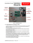
Figure 4-1 shows the YMCRPR8C25 Hardware with major components identified.
Isolated Serial
Connector
Line cord
2x8 LCD Module
Isolated E8a
Debugger Connector
Motor LEDs (4 places)
24 VDC
Power Supply
Motor
Motor Winding
Connection
User Switches
Hall Sensor
Connection
User LEDs (4 places)
Figure 4-1: YMCRPR8C25 System Components
YMCRPR8C25 User’s Manual Rev 1.1
9/ 21
March 2008
4.2. YMCRPR8C25 System Block Diagram
The YMCRPR8C25 board incorporates an R5F21258 (R8C/25) in a 52-pin QFP package from the
R8C/Tiny group of microcontrollers, designated as U17.
Figure 4-2 shows the YMCRPR8C25 block diagram.
R8C25 MCRP Kit
V
B
U
S
CN-4
24v DC
Supply
Power Supply
&
Conditioning
TP-1
TP-5
BLDC
Motor
Speed
Control
R8C/25
MCU
6-PWM
International
Rectifier
(IPM)
CN-1
M
Shutdown
RS232
I/F
Comparators
( Back-EMF)
E8
Debug
I/F
TP-2
OP-AMP
(Signal Conditioning)
Jumper-1
CN-2
TP-3
TP-4
4-LED
PWM / PWR
Status
Hall Sensor
Inputs
Shunt
Current
LCD Segment
Display
CN-3
Push-Button
Switch
Figure 4-2: YMCRPR8C25 Block Diagram
4.3. The YMCRPR8C25 System Component Descriptions
The YMCRPR8C25 System consists of the R8C/25 MCU, an Integrated Power Module and supporting
circuitry, and an LCD module all mounted on a single PCB to drive the included Motor. Below is a detailed
description of the system components.
4.3.1. YMCRPR8C25 Board
The YMCRPR8C25 includes the R8C/25 and support circuitry. Note that to operate the motor the jumpers
must be set correctly for the method selected: sensor (Hall) or sensor-less (Back-EMF). The board is
shipped with the jumpers in the Hall Sensor mode. For details on the jumpers, please consult section 4.5
of this YMCRPR8C25 User’s Manual.
YMCRPR8C25 User’s Manual Rev 1.1
10/ 21
March 2008
4.3.1.1. Jumper Settings
Jumper
JP4
JP5
JP6
JP6
Default setting
1-2
1-2
1-2
3-4
JP6
JP1
JP2
JP3
5-7
1-2, 3-4
1-2, 3-4
1-2, 3-4
Description
Hall W connected to /INT3.
Hall V connected to /INT2.
SW1 Connected to I/O port 1, bit 2 (p1_2).
Over-current Circuit connected to /INT0 for PWM Shutdown
and interrupt generation.
Hall U connected to /INT1.
Don’t change
Don’t change
Don’t change
Table 4.3.1: Hall based Operation
Jumper
JP4
JP5
JP6
JP6
Default setting
2-3
2-3
1-2
3-4
JP6
JP1
JP2
JP3
5-7
1-2, 3-4
1-2, 3-4
1-2, 3-4
Description
BEMF W comparator connected to /INT3.
BEMF V comparator connected to /INT2.
SW1 Connected to I/O port 1, bit 2 (p1_2).
Over-current Circuit connected to /INT0 for PWM Shutdown
and interrupt generation.
BEMF U comparator connected to /INT1.
Don’t change
Don’t change
Don’t change
Table 4.3.2: BEMF based Operation
4.3.2. Emerson Motor
The Emerson Motor included with the kit is a 3-phase BLDC motor. Data sheet is included in the Utilities
Directory of the Install CD under Non-Renesas.
4.3.3. Power Supply
The power supply is a 24VDC, 5A power supply with Center positive barrel connector. The power supply
is intended only to power the system with the motor that is included in the kit.
IMPORTANT: The board does provide a connection for a bench-top power supply. It is
recommended the user review all schematics and take all necessary precautions when trying to use
the system with voltages and currents beyond those required for the motor included with the kit.
4.4. R8C/25 Group of MCUs
The R8C/25 group of 16-bit single-chip Flash microcontrollers (MCU) is part of the R8C/Tiny Family. The
hardware and software manuals for the R8C/25 group of microcontrollers can be found from the Start
menu Start > (All) Programs > Renesas > High-performance Embedded Workshop > Manual Navigator
after software installation.
YMCRPR8C25 User’s Manual Rev 1.1
11/ 21
March 2008
5.0 Motor Control Demo and Support Software
5.1. Overview
The YMCRPR8C25 kit includes two Motor Control Demonstration Application Projects and several
Sample Code projects. These are all accessible through the HEW project generator when creating new
projects.
5.2. Motor Control Demos
5.2.1. HALL Sensor Based BLDC Demo
The HALL Sensor based motor drive algorithm can be generated and built using the Project Generator
installed during the YMCRPR8C25 Kit installation process. Simply launch HEW and Select YMCRPR825
under Project and on the subsequent screen select Application followed by HALL_APPL. The USER is
referred to the Application note on HALL based motor control included with this kit for further details.
NOTE: This algorithm relies on the HALL sensors built into the motor. Please be sure to check the
jumper settings per table 4.3.1.
5.2.2. BEMF (Sensor-less) BLDC Demo
The BEMF (Sensor-less) motor drive algorithm can be generated and built using the Project Generator
installed during the YMCRPR8C25 Kit installation process. Simply launch HEW and Select YMCRPR825
under Project and on the subsequent screen select Application followed by BEMF_APPL. The USER is
referred to the Application note on BEMF (sensor-less) motor control included with this kit for further
details.
NOTE: This algorithm relies on comparator circuits designed into the board (refer to Appendix B for
details). Please be sure to check the jumper settings per table 4.3.2.
5.3. Sample Code
There are additional pieces of Sample code included with the kit that will help you evaluate different
peripherals within the R8C microcontroller. Simply launch HEW and Select YMCRPR825 under Project
and on the subsequent screen select Sample code followed by sample code for the peripheral you wish
to use.
5.4. Windows GUI YMCRPR8C25 Control Program - LEM
5.4.1. OVERVIEW
In order to facilitate motor control and test, the Kit includes a Graphical User Interface program called
LEM which can start and stop the motor and plot various pieces of information about the motor while it is
running. The plots can include such things as speed, current, IPM temperature, etc…
While you have HEW open and connected to the YMCRPR8C25 board through the E8a, launch the GUI
by simply browsing to C:\Workspace\YMCRPR8C25\Utilites and double click on MCRP GUI
icon
(lem.exe). The GUI will launch and take control from the pot and switches on the PCB.
NOTE: Initial screen will ask you to verify the jumpers for the chosen Algorithm
YMCRPR8C25 User’s Manual Rev 1.1
12/ 21
March 2008
Figure 5.4.1: LEM GUI Meter Window
5.4.2. Running Motor
Grab the Speed slider bar and move it above or below the stop point depending on the direction you wish
the motor to rotate. Moving the slider down means to rotate CCW as you face the shaft; moving the slider
up means to rotate CW as you face the motor shaft. Values below the minimum speed of the selected
algorithm will not cause the motor to spin. Returning the slider to 0 will stop the motor. In addition, the
motor may be stopped by selecting the STOP Button. This will also cause the slider to return to the 0RPM selection point.
The E-Stop button flag is sampled at the lowest level of the algorithm. Clicking on it will stop the motor
and return slider to 0-RPM selection point.
5.4.3. Plotting Data
Near real-time data can be plotted in one of the panes of the motor control GUI. Click on the OScope tab,
select the variable to plot and start the motor. See figure 5.4.2 for details. The sample rate of the data
points is 400uS per data value plotted. So if you are plotting four items (variables), you are sampling at
400uS * 4, or 1600uS (1.6mS) update rate.
This data may also be captured in a CSV file for plotting or analyzing under Excel.
YMCRPR8C25 User’s Manual Rev 1.1
13/ 21
March 2008
Figure 5.4.2: LEM GUI OScope Window
6.0 System Details
6.1. Hardware Specifications
Table 6-1 lists the specifications of the YMCRPR8C25 Board.
Table 6-1: YMCRPR8C25 Board Specifications
Item
Specification
MCU
R5F21258, Max clock frequency 20MHz
Clock
Main Clock: crystal 20 MHz
Memory
RAM: 3kB
Flash ROM: 64kB
IPM
10A, IGBT based Power Module
6.2. Power Supply Requirements
The YMCRPR8C25 Board requires a supply voltage of 24.0V DC, and will draw approximately 0.5 amps
when running the included motor with no load. Running the motor under load will require more current.
The kit includes a 120-watt power supply (24VDC @ ~5A) which will drive the motor correctly under
moderate loads. A bench top supply may be used to power the board with other motors.
IMPORTANT: The absolute operating range for the boards power supply input is +18 to +35 VDC.
Connecting to power supplies outside of this range may cause permanent damage to the board.
YMCRPR8C25 User’s Manual Rev 1.1
14/ 21
March 2008
6.3. Operating Environment
The table below lists the environmental conditions for using and storing the YMCRPR8C25 board. Store
the board in a conductive bag inside the original factory packaging.
Table 6-3: Operating and Storage Environments
Environmental Condition
Ambient Temperature
Operating
0 to 55°C
(No corrosive gas allowed)
Storage
-30 to 75°C
(No corrosive gas allowed)
YMCRPR8C25 User’s Manual Rev 1.1
15/ 21
Ambient Humidity
30 to 80% (non-condensing)
30 to 80% (non-condensing)
March 2008
Appendix A. Reference Documents
A.1 Table - Renesas Documents
Item
Title
1.
YMCRPR8C25 Quick Start Guide
2.
3.
4.
5.
6.
7.
YMCRPR8C25 User’s Manual
YMCRPR8C25 Board Schematic
M16C Series Software Manual
R8C/25 Group Hardware Manual
E8a Emulator User’s Manual
HEW User’s Manual
Description
Document that will help you get started on using the
YMCRPR8C25 Starter Kit.
This document.
Schematic diagram for RSK board.
Instruction set for the M16C/R8C series CPU cores.
Operation and Specifications for the R8C/25 MCU
E8A Debugger Manual
Document that describes installation and operation
of this Integrated Development Environment for
Renesas’ Tools.
NOTE:
These manuals can be viewed using the Manual Navigator by clicking on Start > (All) Programs >
Renesas > High-performance Embedded Workshop > Manual Navigator, and expanding the entry for
YMCRPR8C25.
A.2 Table - Other Documents
Item
Title
Description
1.
2.
3.
HEW Target Server QSG
LCD Data Sheet
Emerson/HURST Motor Data Sheet
4.
HEW Target Server Sample code
QuickStart guide for HEW Target Server
Data sheet for ACM0802C LCD
Data Sheet for DMB0224B10002 24VDC BLDC
Motor
Various samples of HEW Target Applications for the
PC.
NOTE:
These documents are contained in the Utilities Folder on the YMCRPR8C25 Install CD.
YMCRPR8C25 User’s Manual Rev 1.1
16/ 21
March 2008
Appendix B. Hardware Notes
B.1 Over-Current Circuit
The YMCRPR8C25 makes current measurements on the low side of the IPM though a 0.05 ohm, noninductive resistor. This shunt voltage is fed into the gain stage (node SU in figure B-1). The gain is set at
2.2.
R120 sets the “trip” threshold on the over-current monitor to provide an “over-current” signal (node FO).
The FO signal is fed to the INT0 pin of the R8C/25 to generate an interrupt and shutdown the PWM
signals to the motor. The Hardware shutdown is to provide fast protection to the power stages in your
motor design, the software signal is to provide a methodology for your software to “recover” or “notify” in
the event of an over-current fault.
The circuit comes from the factory with the trip point (pin 2 of R120) set to 1.0 Volts, which equates to a
trip point of about 4.9A at 85% duty cycle on the PWM.
NOTE: this circuit measures the Bus current which in 6-step is typically the same as motor current. For
other modulation methods, this may not be the case and customer is advised to analyze their
requirements when utilizing other modulation methods.
Figure B-1: Over-current Circuit
YMCRPR8C25 User’s Manual Rev 1.1
17/ 21
March 2008
B.2 Back-EMF Detect Circuit
The YMCRPR8C25 uses filters, divider resistors and comparators to detect the Back-EMF in hardware.
Figure B-2 shows the Filter/Divider combination.
To Motor Outputs
Figure B-2: Back-EMF divider and filters
The outputs are then fed to comparators to detect the correct threshold for “zero-cross” in the motor. One
typical circuit is shown in Figure B-3.
Figure B-3: Back-EMF comparator
B.3 Temperature Sensor
The IPM (Intelligent Power Module) includes a Thermistor on the same substrate as the IGBTs. This is
used to measure the temperature of the transistor module, as is shown on the LEM GUI Display.
YMCRPR8C25 User’s Manual Rev 1.1
18/ 21
March 2008
Appendix C. PCB Component Layout
C.1 Component Placement - Top
Figure C.1: Component Placement – Top
YMCRPR8C25 User’s Manual Rev 1.1
19/ 21
March 2008
C.2 Component Placement - Bottom
Figure C.2: Component Placement - Bottom
YMCRPR8C25 User’s Manual Rev 1.1
20/ 21
March 2008
Appendix D. Troubleshooting
D.1 Serial Communications
The YMCRPR8C25 board requires the E8a debugger and an operational COM port in order to run the
board from the LEM GUI. The COM port can be an problem on some computers that do not have a
hardware COM port, or which do not have it on COM1.
D.1.1 Setting the COM Port Number
If the COM port available is not COM1, then change the default port in lem.ini. Open lem.ini with a
text editor. Find the ComPort=1 field (line 29), and change the number 1 to the actual port being
used. This port must be in the range of 1 through 9. Save the file and run LEM.exe again.
D.1.2 USB COM Ports
Using a USB COM port will often change the port number on each time the PC is booted or the USB
COM port is plugged in. Find the actual port used in Hardware Manager. Set lem.ini ComPort setting
to match the actual port, or change the USB port to match the .ini file.
D.1.3 LEM Serial Errors
LEM attempts to get rapid updates from the YMCRPR8C25 board through the serial COM port.
When the COM settings do not allow this, the program may report an Overrun Error. The first thing to
check is the port settings in Hardware Manager, Properties, Port Settings, Advanced, FIFO. Make
sure the FIFO option is enabled.
For USB-Serial adapters, the Advanced port settings vary widely, depending on the adapter. Try the
FIFO option first, if available. If you have a Latency option, set it to minimum. If you have timout
options, try setting them to minimum. If your options vary from these and you still have problems, it is
recommended you write down the default settings, and try other options that might reduce the time
delay between the PC serial interface. This might include closing other Windows applications.
If there is a COM port conflict, such as when a PDA sync program is running, it might be necessary to
change the COM port channel or temporarily disable the conflicting program.
Some Serial adapters simply cannot provide the lowest latency communication link to the LEM
program. This may result in the LEM GUI showing locked display data, reporting communication
errors, numerous fault indicators lighting, or the OScope images not changing with commands. For
these situations, the best option may be to reset the communication channel when a fault occurs,
which can be done by sending a new speed command by sliding the Speed bar, or hitting the “Set
RPM” button.
D.2 LEM Hangs
If during startup of LEM, it hangs or reports the board is not connected, it may be that HEW Target Server
(HTS) is not registered in HEW. Follow the directions in the HTS manual for registering, found in the
Manual Navigator. It may be necessary in some cases to un-register a previous version of HTS before
registering the new one.
YMCRPR8C25 User’s Manual Rev 1.1
21/ 21
March 2008


