1
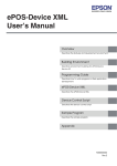
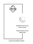
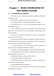
AH8000
DIGITAL SMARTHOME
ADMIN UNIT Software Version
USER MANUAL
PREFACE
Thanks for purchasing Aurine AH8000 2.0 (digital
smarthome system) series products. Please read the manual
carefully to ensure your convenient use.
All the information on characteristics and performances
of our products are subject to change without notice .Welcome
to download the updated version on our website.
Product photos here is for your reference only, actual item
may differ.
№ 201112-A0
PAGE 1
Contents
Contents
1. Installation ........................................................3
1.1 Installation Environment ...........................................3
1.2 Installation Files .................................................3
1.3 Installation Procedure..............................................3
1.4 Initial Settings ...................................................8
1.4.1 Client connection ............................................9
1.4.2 Authorization via Central Server .................................9
1.4.3 Network Parameters Settings ...................................9
1.4.4 Change IP address ............................................10
1.4.5 First Login .................................................12
2. Function ..........................................................13
2.1 Terms .........................................................13
2.2 Intercom .......................................................13
2.2.1 Place a call .................................................14
2.2.1 Answer a call ...............................................15
2.2.3 Monitor primary/secondary entry ................................15
2.2.4 Unlock the gate ..............................................16
2.3 E-map Monitoring ................................................17
2.4 Events Monitoring ...............................................18
2.4.1 Alarm events monitoring.........................................18
2.4.2 Normal events monitoring ...................................19
2.4.3 Patrol events monitoring ....................................20
2.4.4 Event Inquiry ...............................................20
2.5 Devices Monitoring...............................................21
2.6 Exit the system ..................................................23
PAGE 2
1
INSTALLATION
1.1 Installation Environment
1)
Operating System:
WINDOW XP SP2 /WINDOWS 2003 SP1 with Microsoft DIRECTX 9.0
installed
2) Operating Environment
CPU: P4 1.8G/C4 2.4G or above (above P4 2.4G/ C4 3.0G preferable)
RAM: minimum 512M (1G or above preferable)
Network Card: 10/100Mbps; 10/100/1000Mbps
Sound Card: required
3) Hard Drive Space
System: 40M
Database: minimum 2G (10G preferable)
1.2 Installation Files
SOFTWARE
FILE
Admin Unit Software
Manager-Setup.exe
Dongle Driver
MicroDogInstdrv.exe
1 . 3 Installation Procedure
1) Run Manager_Setup.exe.
2) Choose English and then click Next.
Fig . 1
PAGE 3
3) Click Next to continue.
Fig. 2
4) Type the user information (name&company) as required, and then
click Next.
Fig. 3
PAGE 4
5) Choose a destination folder and then click Next to continue.
Fig. 4
Change default destination: click Change and then select/type a
destination. Then click OK.
Fig. 5
PAGE 5
6) Click Install to continue.
Fig. 6
7) Click Finish to complete the installation.
Fig. 7
PAGE 6
Install Dongle Driver
1 ) Double- click MicroDogInstdrv.exe and then check USB Dog
Driver.
Driver not
installed yet
Dongle Type
Fig. 8
2) Click Install Driver to start the installation .
Driver installed!
Fig. 9
3) Click Exit.
PAGE 7
1.4 Initial Settings
Before the first use, client connection and authorization via center
server are required.
1.4.1 Client connection
* If there are multi-clients in the system, client connection shall be carried out on
every client (Admin Unit software).
Click start
Programms
Digital SmartHome System V2.0
Tool
Database-Client Connection
PC name where
server is installed
Fig. 10
1) Check ServerConfig and then type the user name (default: sa) and the
password set when the database is installed.
set when database
is installed
Fig. 11
2)Check ClientConn and then click Connect to finish the connection.
PAGE 8
1.4.2 A uthorization via Central Server
Admin Unit should be authorized via Central Server before use. For
details, refer to Section 2.3.5 in the User Manual of Central Server.
1.4.3 Network Parameters Settings
1) right-click My Network Places and then click Properties;
2) double-click Local Area connection and then click Properties;
3) double-click Internet Protocol (TCP/IP);
Fig. 12
4) check use the following IP address and then click Advanced;
Fig. 13
PAGE 9
5) click Add to add IP address and subnet mask;
Fig. 14
6) click Add to add gateway address and then click OK;
Fig. 15
PAGE 10
7) Click Enter to save the settings.
Fig. 16
1.4.4 Change IP address
1) Right-click on the shortcut Digital SmartHome System-Admin Unit
and then click Properties;
2) Click Find Targe...;
3) Open “SZJJ_Manager.ini”with notepad;
4) Change IP address under "IPAddr” as set on Step 1.4.2;
5) Save the settings.
Fig. 17
PAGE 11
1.4.5 First Login
1) Open Digital SmartHome System-Admin Unit;
2) Enter User No. (default: system) and password(default: 123456).
*The system will oblige the user to change the default password after the first login .
Fig. 18
PAGE 12
2
FUNCTIONS
2.1 Terms
1) User: system operator;
2)Indoor Terminal: terminal installed inside a apartment for resident;
3) Public Terminal: Primary Entry Terminal/Secondary Entry Terminal;
4) Monitor: real-time view of the video captured by built-in camera in one
terminal, launched from another terminal
5) Talk: bidirectional audio/video communication between two terminals
2.2 Intercom
Main Screen
Video
Keypad
Functions
Calls Register
Fig. 19
PAGE 13
2.2.1 Place a call
You may place a call to Indoor Terminal or other Admin Unit on the
Admin Unit.
Method 1
a. Enter a device number on keypad;
b. Click Call to place a call.
*To give up the call, click Hang Up or *.
Device number of Admin Unit: 51-90.
For details of device number of Indoor Terminal, see Parameters Settings
in User Manual of Center Server.
Method 2
a. Right-click Call;
b. Select a device on the popped-up list (Fig. 20), and then click OK
to place a call.
Fig. 20
2.2.2 Answer a call
a. When there is an incoming call, the Admin Unit will ring and display
the caller (except Indoor Terminal) video and ID;
b. Click Answer to answer it.
*To refuse the call, click Hang Up.
PAGE 14
2.2.3 Monitor primary/ secondary entry
You may monitor primary/secondary entry via Primary/Secondary
Entry Terminal on Admin Unit.
Method 1
a. Enter a device number;
b. click Monitor to start the monitoring (monitor time: 60s).
To give up the monitoring, click End.
Method 2
a. Right-click Monitor;
b. Select a device on devices list (Fig. 21);
c. Click OK to start monitoring.
Fig. 21
PAGE 15
2.2.4 Unlock the gate
During a talk/ surveillance with Primary/Secondary Entry Terminal ,
click Unlock to release the gate at primary/secondary entry.
Fig. 22
PAGE 16
2.3 E-map Monitoring
You may check status of devices and sensors in the system on E-map, and
carry out functions like arm/disarm the system, placing a call and
monitoring.
* To switch to a certain map, you may click the device number on the
Map List or click the hyperlink on the map.
Map
List
Display
Area
Function
Icons
Fig. 23 (a)
Back
Display
Area
Intercom
Icons
Fig. 23 (b)
PAGE 17
1) Display Area: check different devices and their working status
through their corresponding icons on map;
2) Map List: click the device number on the list to switch map
3) Back: click it to return to the previous class (superclass)
4) Function Icons: Alarm icons (arm/disarm/alarm sound)and Intercom
icons (call/monitor)
2.4 Events Monitoring
2. 4.1 Alarm events monitoring
Alarm events list includes alarm type, location, time, description, as
well as processor, result and processing time if the alarm is processed.
*Once an alarm occurs, E-map with alarm indication will be popped
up and the alarm bell will sound. You may check alarm information on
devices monitoring, alarm events list and E-map.
Fig. 24
PAGE 18
To process an alarm, double click the alarm and then select a
result on the popped-up window.
Fig. 25
2.4.2 Normal events monitoring
Normal Events include intercom events, security operations and
access events, etc.
Fig. 26
PAGE 19
2.4.3 Patrol event monitoring
Patrol events will be listed here synchronously, including card
number, patrol time, patrol place and the description.
To check the historical records of patrol events, select Patrol
Monitoring.
Fig. 27
2.4.4 Event inquiry
You may inquire alarm events, normal events and patrol events on
Admin Unit.
Fig. 28
PAGE 20
2.5 Devices Monitoring
a. To monitor a Public Terminal
Select a riser/Primary Entry Terminal on the menu tree and then click
the icon of the terminal. Then click Monitor.
b. To arm/disarm an apartment or call a resident
Select a riserl on the menu tree and then click the icon of the terminal.
Then click Home/Night/Away/Call upon actual need.
Menu
Tree
Fig. 29 (a)
The security status (i.e., Home/Away/Night mode and alarm status)
will be expressed in different icons as belows.
Home Mode
Away Mode
Alarming Status
Night Mode
Fig. 29 (b)
PAGE 21
2.6 Exit the system
Click Exit and then click Yes to exit the system.
PAGE 22
Admin Unit User Manual
● The information in this manual is subject to change without prior notice.