1
X91384MIO UK
EN COOKER HOOD
USER MANUAL
3
FOR PERFECT RESULTS
Thank you for choosing this AEG product. We have created
it to give you impeccable performance for many years, with
innovative technologies that help make life simpler – features you might not find on ordinary appliances. Please spend
a few minutes reading to get the very best from it.
ACCESSORIES AND CONSUMABLES
In the AEG webshop, you’ll find everything you need to keep
all your AEG appliances looking spotless and working perfectly. Along with a wide range of accessories designed and
built to the high quality standards you would expect, from
specialist cookware to cutlery baskets, from bottle holders to
delicate laundry bags…
Visit the webshop at:
www.aeg-electrolux.com/shop
Contents
3
CONTENTS
5
6
7
9
15
Important safety information
Your appliance
Operating instructions
Maintenance and cleaning
Installation instructions - electrical
connections
4
Thank you for buying an AEG product.
To enable you to use your appliance effectively and safely, please read this instruction book carefully before using the appliance and
retain for future reference. If you require guidance in the use of the appliance or require further information on AEG Products, please
contact our Customer Services Department. For general enquiries concerning your AEG appliance or for further information, visit our
website at http:\\www.aeg.co.uk
Customer Services Department
Major Appliances
AEG
Addington Way
Luton
Bedfordshire LU4 9QQ Tel: 08705 350 350(*)
* calls to this number may be recorded for training purposes.
For the Installer
For the User
Installation Instructions
Important Safety Information
Technical Information
Your Appliance
Electrical Connections
Electrical Requirements
Electrical Connection
Operating Instructions
Cooker Hood Controls
To Operate
Recirculation
Extraction
Installing the Cooker Hood
Installation Requirements
Unpacking
Clearance Height
Wall drilling and bracket fi xing
Hood body mounting
Drilling the Shelves
Chimney assembly
Top Shelf
Maintenance and Cleaning
External Cleaning
Metal Grease Filter
To Remove the Grease Filter Cassette
Charcoal Filter
To Remove/Replace the Charcoal Filter
Worktop Lighting
Replacing the Light Bulb
Electrical Connection and Working Test
Something Not Working
Service and Spare Parts
Guarantee Conditions
Guide to use the instruction book
The following Symbols will be found in the text to guide you through the instruction book
Safety instructions
Step by step instructions
5
IMPORTANT SAFETY INFORMATION
IMPORTANT SAFETY INFORMATION
These warnings are provided in the interests of your safety. Ensure that you understand them all before installing or using
this appliance. Your safety is of paramount importance. If you are unsure about any of the meanings of these warnings
contact the Customer Services Department.
Installation
• Any installation work must be undertaken by a qualified
electrician or competent person.
• This hood must be installed in accordance with the installation
instructions and all measurements adhered to.
• If the cooker hood is installed for use above a gas appliance
then the provision for ventilation must be in accordance
with the Gas Safety Code of Practice BS.6172, BS.5440 and
BS.6891 (natural gas) and BS.5482 (LP gas) 1994, the Gas
Safety (Installation & Use) Regulations, the Building Regulations issued by the Dept. of the Environment, the Building
Standards (Scotland) (Consolidated) Regulations issued by the
Scottish Development Department.
• The fan motor of the cooker hood incorporates a cut-out
device, which will operate if the cooker hood is installed
below the minimum height recommended in the Technical
Information section, or if the motor becomes overheated.
If the cut-out device is activated, switch off the motor and
allow the hood to cool. The cut-out device will reset itself
when the fan motor has cooled.
• It is dangerous to alter the specifications or modify this
product in any way.
• When installed between adjoining wall cabinets, the cabinets
must not overhang the hob.
• If the room where the hood is to be used contains a fuel
burning appliance such as a central heating boiler then its
flue must be of the room sealed or balanced flue type.
• If other types of flue or appliances are fitted ensure that
there is an adequate supply of air to the room.
• When the hood is used in conjunction with appliances supplied
with energy other than electricity, the negative pressure in
the room must not exceed 0.04mbar to prevent fumes being
drawn back into the room by the hood.
• The ducting system for this appliance must not be connected
to any existing ventilation system which is being used for
any other purpose.
• Do not install above a cooker with a high level grill.
Child Safety
• The appliance is designed to be operated by adults. Children
should not be allowed to tamper with the controls or play
with the appliance.
During Use
• This appliance is for domestic use only.
• Never leave frying pans unattended during use as over-heated
fats and oils might catch fire.
• Never do flambé cooking under this cooker hood.
• Do not leave naked flames under this hood.
Maintenance and Service
• This appliance can be a fire hazard if the grease and charcoal
filters are not cleaned or replaced as recommended.
• Under no circumstances should you attempt to repair the
appliance yourself. Repairs carried out by inexperienced
persons may cause injury or serious malfunctioning. Refer
to your local Service Force Centre. Always insist on genuine
spare parts.
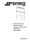
YOUR APPLIANCE
YOUR APPLIANCE
����
����
����� �����
6
7
OPERATING INSTRUCTIONS
OPERATING INSTRUCTIONS
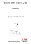
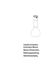
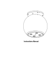
A
B
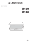
Button Function
C
D
E
F
Specifications
A
Hood Functions On/Off
When the button is touched with the hood turned off, all functions light up
(intensity 50%) and are enabled.
When the button is touched with the hood in operation, all functions are turned
off and disabled (Motor Off + Lights Off).
B
Manages motor speed:
0-V1-V2-V3-V4-P
When the area is touched, the motor starts at the speed required.
P = Intensive Speed, timed for 5 minutes, after which the system returns to the
previous speed.
When activated from Motor Off it returns to speed V1.When the required speed
is touched, it will become brighter (intensity 100%) than the other functions
(intensity 50%).
C
Delay function
Touching this button activates automatic shutdown of the Motor, the Fans and
the Lighting with a 10 minute delay. It can only be activated with the motor on,
running at any speed except Intensive, and with the Sensor = Off.
Enables / Disables the
Remote Control Receiver.
When this button is pressed and held for 4 seconds (Motor Off + Lights Off, in
the absence of other alarms, the Led will light up for:
4 seconds to indicate that the Remote Control has been Activated
2 seconds to indicate that the Remote Control has been Deactivated
D
Sensor
In this mode the Hood operates automatically for a maximum of 5 hours, after
which it switches the Motor off.
The hood modifies the speed of the motor according to the findings of the sensor.
Buttons B and C do not work. The function is disabled by pressing the Button or
turning the hood off.
E
Manages Lighting Intensity: 0-L1-L2-L3-LMax
When this area is touched, the Lights turn on at the required intensity.
When the lighting intensity is touched, it will become brighter (intensity 100%)
than the other functions (intensity 50%).
F
Filter ResetResets the
Filter Saturation alarm
when the button is touched with the motor and
lighting turned off.
After 100 hours operation the Led lights up continuously to indicate saturation of
the Metal Grease Filters.
After 200 hours operation the Led flashes to indicate saturation of the Activated
Charcoal Filters.
Enables/Disables the
Activated Charcoal Filter
Alarm.
When this button is pressed and held for 4 seconds(Motor Off + Lights Off), in the
absence of other alarms, the Led will light up for:
4 seconds to indicate the Activated Charcoal Filter Alarm has been activated
2 seconds to indicate the Activated Charcoal Filter Alarm has been deactivated
After connecting the hood to the mains, the commands are activated after 4seconds. When the Hood is switched off, none of the functions is displayed, and only the normal lettering on the control panel is visible. All the rest will light up (intensity 50%) when button A is
touched.
The controls are activated by touching the selected function, which will light up more brightly (intensity 100%) with respect to the other
hood functions (intensity 50%). When no commands are given for at least 10 seconds, only the selected functions will be lighted (Intensity 100%) and all the rest will turn off (Intensity 50%). After 7 hours in operation, if no further commands are given the hood will switch
off (Motor Off + Lights Off), from here you can touch for activated the function, and the next touch you can select the desired function.It
is possible to activate one of the hood functions (Speed and Lighting) not just by touching the control panel, but also by placing a finger
on the panel and sliding it towards the chosen function without lifting it off. If the motor and lights are turned off, by setting them to
zero, all the command LEDs will remain on at 50%, and if no further commands are given in the next 10 seconds, then all the LEDs will be
turned off with the exception of the “0” LEDs, which will remain on for a further 15 minutes.
OPERATING INSTRUCTIONS
Hood Options in Sensor mode
When operating in Sensor mode, the type of
hob being used has an influence. Two options
are available:
• Electric hob ;
• Gas hob
Initially it is set to electric hob. To change the
setting, proceed as follows:
• Turn the hood off using the hood on/off
button
• Press and hold the Sensor button for 8
seconds until the LED flashes as described:
• 4 flashes indicate selection of the electric
hob;
• 2 flashes indicate selection of the gas
hob;
• Remove power for 10 seconds and then
reconnect it.
The calibration procedure is carried out every
time the type of hob is changed.
Calibration procedure: every time the hood is
turned on or the type of hob is changed, the
sensor calibration procedure is run. During this
time the hood must not be used for cooking
or subjected to particularly intense smells, for
example solvents or detergents.
This process requires:
• 13 minutes if the electric hob has been
selected;
• 1 minute if the gas hob has been selected;
This phase is marked by flashing of the LED on
the sensor button, if it has been pressed.Do not
turn the motor on during calibration.
Warning: Do not spray directly on the grill
cleaning products but only clean with a cloth
soaked in detergent. Avoid cleaning the grill
alcohol or silicone products.
8
OPERATING INSTRUCTIONS
9
OPERATING INSTRUCTIONS
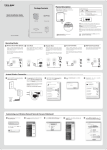
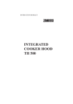
This cooker hood can be used to recirculate or extract contaminated air.
Recirculation Mode
The cooker hood is supplied specified for use in the recirculation
mode with the charcoal filter fitted.
The contaminated air is cleaned by passing through the filters and
than back into the kitchen.
���
The activated charcoal filter absorbs odours arising from cooking. In
use it will slowly become saturated in grease and less effective. The
filter normally requires changing after at least every three months
or more frequently if the hood is used for more than three hours
per day.
• Insert the Connector extensions 14.1 into the side of
the Connector 15.
• Insert the Connector 15 into the Support bracket 7.3
and fix it with the screws.
• Fasten the Support bracket 7.3, fixing it to the upper
part with the Screws.
• Make sure that the Connector extensions outlet 14.1
is in correspondence with the Chimney openings both
horizontally and vertically.
• Join the Connector 15 to the Hood canopy outlet us-ing
a rigid or flexible pipe ø¸150 mm, selection of which is
at the discretion of the installation technician.
• Make sure that the Activated charcoal odour filter has
been fitted.
Extraction (Ducted)
The cooker hood is more effective when installed in the extraction
mode (ducted to the outside).
Venting kits may be purchased through your retailer or DIY store,
and must be evacuated through an outside vent of ø125 (5ins) or
ø150mm (6ins).
The ducting used must be manufactured from fire retardent material conforming to the relevant British Standard or DIN 4102-B1.
When the cooker hood is ducted to the outside the charcoal filter
must be removed.
When installing the ducted version, connect the hood to the chimney using either a flexible or rigid pipe ø 150 or 120mm, the choice
of which is left to the installer.
To install a ø 150
• To install the dumper 10.
• Fix the pipe in position using sufficient pipe clamps (not supplied).
To install a ø 120
• To install a ø 120 mm air exhaust connection, insert the reducer
flange 9 on the dumper 10.
• Fix the pipe in position using sufficient pipe clamps (not supplied).
• Remove any activated charcoal filters.
���
����
��
���
���
Fitting the Ducting
• To install the Ducting Version of the hood, the optional
Ducting chimney kit must be purchased.
Never do flambé cooking under this cooker hood.
Take extra care when frying and never leave frying
pans unattended during use, as over-heated fats and
oils can catch fire.
Do not leave naked flames under the cooker hood.
Ensure the hood is switched on before using the hob.
Ensure heating areas on your hob are covered with
pots and pans when using the hob and cooker hood
simultaneously.
Ensure not to damage the charcoal filter when
cleaning or replacing as the activated charcoal inside
is saturated with grease, which will stain if it comes
into contact with clothing or furnishings.
�����
��
��
�����
��
�
��
10
MAINTENANCE AND CLEANING
MAINTENANCE AND CLEANING
Before carrying out any maintenance or leaning isolate the
cooker hood from the mains supply.
The cooker hood must be kept clean, as a build up of grease
or fat can be a fire hazard.
External Cleaning
The metal casing, grille and chimney should be cleaned at least once
a month to keep it looking like new. Wipe over the hood with a soft
cloth wrung out in mild
soapy water and then dry thoroughly.
Never use scouring pads or abrasive cleaners as they may scratch or
damage the surfaces.
Always wear protective gloves when cleaning the hood.
Never use scouring pads or abrasive cleaners.
Never use excessive amounts of water when cleaning particularly around the control panel.
Alarm signal reset
• Turn the Lights and the Suction Motor off.
• Touch button F. The operation is confirmed when the Led goes
out.
Metal Grease Filters
These filters can be washed in a dishwasher, and need to be cleaned
when the Led on Button F lights up in a con-tinuous manner or at
least once every approximately two months' use, or more frequently
in the case of particularly intensive use.
To Remove the Grease Filter
• Remove the Filters one at a time, supporting them with one hand
while you pull the lever down with the other.
• Wash the Filters without bending them, and leave them to dry
completely before replacing.
• Replace, taking care to ensure that the handle faces for-wards.
MAINTENANCE AND CLEANING
MAINTENANCE AND CLEANING
Alarm signal reset
• Turn the Lights and the Suction Motor off.
• Touch button F. The operation is confirmed when the Led
goes out.
Before carrying out any maintenance or cleaning isolate
the cooker hood from the mains supply.
Charcoal Filters
In the recirculation mode the charcoal filters absorb smells and
unwanted odours.
This cannot be washed or regenerated, and must be changed
when the led on button F starts to flash, or at least once every
4 months.
Enabling/Disabling the alarm signal
• In Recirculation Version Hoods, the Filter Saturation Alarm
must be activated on installation or at a later date.
• Turn the Lights and the Suction Motor off.
• Press button F and hold it for 4 seconds until the LED
lights up in confirmation:
•
Led lights up for 4 seconds – Activated Charcoal
Filter saturation alarm ACTIVATED.
•
Led lights up for 2 seconds – Activated Charcoal
Filter saturation alarm DEACTIVATED.
To Remove the Charcoal Filters
• Remove the metal grease filters.
• Remove the saturated activated carbon filter by releasing the
fixing hooks.
• Fit the new filter by hooking it into its seating.
• Refit the metal grease filters.
This appliance can be a possible fire hazard if the grease
and charcoal filters are not cleaned and replaced as
recommended.
11
12
MAINTENANCE AND CLEANING
MAINTENANCE AND CLEANING
Changing the Lighting
Warning: This appliance is fitted with a white LED lamp classed
as 1M according to EN 60825-1: 1994 + A1:2002 + A2:2001
standards; maximum optical power emitted @439nm: 7µW. Do
not look directly at the light through optical devices (binoculars,
magnifying glasses…).
• For replacement contact technical support. ("To purchase contact
tech-nical support")
Replacement filters and light bulbs can be obtained from
your local Service Force Centre.
SOMETHING NOT WORKING - SERVICE AND SPARE PARTS
13
SOMETHING NOT WORKING
If, having followed these instructions carefully, your cooker hood fails to work properly please carry out
the following checks.
Solution
Symptom
The cooker hood will not start
• Check the hood is connected to the electricity supply.
• Check that the fan speed control is set to 1, 2 or 3.
The cooker hood is not working effectively
• The fan speed is set high enough for the task.
• The grease filter is clean.
• The kitchen is adequately vented to allow the entry of fresh
air.
• If set up for recirculation, check that the charcoal filter is
still effective.
• If set up for extraction, check that the ducting and outlets
are not blocked.
The cooker hood has switched off during operation
• The safety cut-out device has been tripped.
• Turn off the hob and then wait for the device to reset.
I
f after all these checks, the problem persists, contact your local
Service Force Centre, quoting the model and serial number.
Please note that it will be necessary to provide proof of purchase
for any in-guarantee service calls.
In-guarantee customers should ensure
that the above checks have been made as
the engineer will make a charge if the fault
is not a mechanical or electrical
breakdown.
SERVICE AND SPARE PARTS
If you require an engineer or wish to purchase spare parts contact your local Service Force Centre by telephoning:
08705 929929
Your telephone call will be routed to the Service Force Centre
covering your postcode area.
For general enquires concerning your AEG appliance or for further information on AEG products, please contact our Customer
Services Department at the address below or visit our website at
www.aeg.co.uk
Customer Services Department
Major Appliances
AEG
Addington Way
Luton
Bedfordshire
LU4 9QQ
Tel: 08705 350 350 *
* calls to this number may be recorded for training purposes
14
GUARANTEE CONDITIONS
GUARANTEE CONDITIONS
Standard Guarantee Conditions
We, AEG, undertake that if within 12 months of the date of the purchase this AEG built-in appliance or any part thereof is proved to be
defective by reason only of faulty workmanship or materials, the company will, at our option, repair or replace the same FREE OF ANY
CHARGE for labour, materials and carriage on condition that:
• The appliance has been correctly installed and used only on the electrical supply stated on the rating plate.
• The appliance has been used for normal domestic purposes only, and in accordance with the manufacturer’s operating and
maintenance instructions.
• The appliance has not been serviced, maintained, repaired, taken apart or tampered with by any person not authorised by us.
• All service work under this guarantee must be undertaken by an AEG Service Force Centre.
• Any appliances or defective parts replaced shall become the property of this company.
Home visits are made between 8.30am and 5.30pm Monday to Friday. Visits may be available outside these hours in which case a
premium will be charged.
EXCLUSIONS
This Guarantee does not cover:
• Damage or calls resulting from transportation, improper use or neglect, the replacement of any light bulbs or removable parts
of glass or plastic.
• Costs incurred for calls to put right appliances improperly installed or calls to appliances outside the United Kingdom.
• Appliances found to be in use within a commercial environment, plus those which are the subject of rental agreements.
• Products of AEG manufacture which were not marketed by AEG. This guarantee is in addition to your statutory and legal
rights.
EUROPEAN GUARANTEE
If you move to another country within Europe then your guarantee moves with you to your new home subject to the following
qualifications:
• The guarantee starts from the date you first purchased your product.
• The guarantee is for the same period and to the same extent for labour and parts as exists in the new country of use for this
brand or range of products.
• The product is installed and used in accordance with our instructions and is only used domestically, i.e. a normal household.
• The product is installed taking into account regulations in your new country.
Before you move please contact your nearest Customer Care centre, listed below, to give them details of your new home.
They will ensure that the local Service organisation is aware of your move and able to look after you and your appliance.
France
Germany
Italy
Sweden
UK
Senlis
Nurnberg
Pordenone
Stockholm
Luton
+33 (0)3 44 62 29 99
+49 (0)911 323 2600
+39 (0)01678 47053
+46 (0)8 738 79 50
+44 (0)8705 350 350
INSTALLATION INSTRUCTIONS - ELECTRICAL CONNECTIONS
15
INSTALLATION INSTRUCTIONS
It is dangerous to alter the specifications or attempt to modify this product in any way.
Technical Information
DIMENSIONS HEIGHT (CANOPY): HEIGHT (CHIMNEY): WIDTH (CANOPY):
WIDTH (CHIMNEY):
GROSS: NET:
ELECTRICAL SUPPLY: POWER CONSUMPTION:
FAN MOTOR: LAMP: (4x4W) Led
SUITABLE FOR INSTALLATION
ABOVE: ELECTRIC HOB: GAS HOB: SLOT-IN GAS COOKER SLOT-IN ELECTRIC COOKER 60 mm
695 - 415 mm
998 mm
350 mm
19,5 kg - 20 kg
15,5 kg - 17,2kg
220-240 V (50 Hz)
285 W
260 W
16 W
7 KW
10 KW
13.5 KW
12.4 KW
Note: CE Marking certifies that this appliance complies with the requirements laid down
in EEC directive 89:336. (Electromagnetic compatibility) and subsequent modifications
and Low Voltage directive 72/23/E.
ELECTRICAL CONNECTIONS
This appliance must be earthed
Electrical Requirements
Any permanent electrical installation must comply with
the latest I.E.E. Regulations and local Electricity Board
regulations. For your own safety this should be undertaken by a qualified electrician e.g. your local Electricity
Board, or a contractor who is on the roll of the National
Inspection Council for Electrical Installation Contracting
(NICEIC).
Electrical Connection
Before connecting to the mains supply ensure that the
mains voltage corresponds to the voltage on the rating
plate inside the cooker hood.
Remove the grease filters (see paragraph Maintenance)
being sure that the connector of the feeding cable is
correctly inserted in the socket placed on the side of
the fan.
This appliance is fitted with a 3 core mains cable and
must be permanently connected to the electricity supply
via a double-pole switch having 3mm minimum contact
gap on each pole. A Switched Fuse Connection Unit to
BS1363 Part 4, fitted with a 3 Amp fuse, is a recommended mains supply connection accessory to ensure
compliance with the Safety Requirements applicable to
fixed wiring instructions.
This appliance conforms to BS 800: 1988 and EEC
Directive No. 78 308 regarding suppression of radio and
television interference.
16
INSTALLING THE COOKER HOOD
INSTALLING THE COOKER HOOD
Please ensure that when the appliance is installed it is easily accessible to an engineer in the event of a breakdown.
All installations must comply with the local authorities
requirements for the discharge of exhaust air.
Incorrect installation may affect the safety of this
cooker hood.
Installation Requirements
Before installation check the wall to
which the cooker hood is to be fitted for
electric cables, water pipes or gas.
The chimney hood must be installed according to the
instructions suppliers below and by qualified and competent personnel to the relevant National Standards.
The cooker hood is designed to be fixed to a solid block or block
wall over a cooking area. If not, suitable fixing must be used
for other types of walls. The hood can be used in the extraction
(ducted to the outside) or recirculation (internal recycling) mode.
The Installation work must be undertaken by a qualified and
competent person. The manufacturer disclaims any responsibility
to damages due to incorrect installation of
the cooker hood or if the cooker hood is not installed in
compliance with relevant regulations controlling this type of
installation.
��
��
��
��
���
����
���
���
���
��
���
���
����
���
�
���
�
��
��
���
���
���
�
���
��
���
Before unpacking the cooker hood position the carton with the
arrows pointing upwards as illustrated on the carton.
The canopy is supplied with the following components for
installation:
Ref Qty
1
1
2
2.1
2.2
7.1
1
1
1
1
7.1a
7.1b
9
10
14.1
15
24
25
50
1
1
1
1
2
1
1
1
Ref. Q.ty
7.3
1
11
4
12c 8
12e 4
12f 2
12g 4
12h 4
12q 4
21
1
22
8
23
4
��
����
���
Unpacking
��
Q.ty
1
Product Components
Hood Canopy complete with: Controls,
Lights, Filters
Telescopic chimney made up of:
Upper chimney
Lower chimney
Telescopic frame complete with Suction fan,
made up of:
Upper frame
Lower frame
Reduction flange ø 150-120 mm
Damper ø 150
Air Outlet Connection Extension
Air Outlet Connection
Connection box
Hose clamps (not included)
Control Board Group
Installation components
Air Outlet Connection Support
Wall Plugs ø 10
Screws 2,9 x 6,5
Screws 2,9 x 9,5
Screws M4 x 80
Screws M6 x 80
Screws 5,2 x 70
Screws 3,5 x 9,5
Drilling template
6.4 mm int. dia washers
M6 nuts
Documentation
Instruction booklet
INSTALLATION INSTRUCTIONS
INSTALLATION INSTRUCTIONS
Drilling the Ceiling/shelf and fixing the frame
• Use a plumb line to mark the centre of the hob on the ceiling/
support shelf.
• Place the drilling template 21 provided on the ceiling/support
shelf, making sure that the template is in the correct position
by lining up the axes of the template with those of the hob.
• Mark the centres of the holes in the template.
• Drill the holes at the points marked:
• For concrete ceilings, drill for plugs appropriate to the screw
size.
• For hollow brick ceilings with wall thickness of 20 mm: drill ø
10 mm(immediately insert the Dowels 11 not supplied).
• For wooden beam ceilings, drill according to the wood screws
used.
• For wooden shelf, drill ø 7 mm.
• For the power supply cable feed, drill ø 10 mm.
• For the air outlet (Ducted Version), drill according to the diameter of the external air exhaust duct connection.
• Insert two screws of the following type, crossing them and
leaving 4-5 mm from the ceiling:
• For concrete ceilings, use the appropriate plugs for the screw
size (not provided).
• for Cavity ceiling with inner space, with wall thickness of
approx. 20 mm, Screws 12h, supplied.
• For wooden beam ceilings, use 4 wood screws (not provided).
• For wooden shelf, use 4 screws 12g with washers 22 and
nuts 23, provided.
17
18
INSTALLATION INSTRUCTIONS
INSTALLATION INSTRUCTIONS
Fixing The Frame
• Loosen the two screws fastening the lower chimney and remove
this from the lower frame.
• Loosen the two screws fastening the upper chimney and remove
this from the upper frame.
If you wish to adjust the height of the frame, proceed as follows:
• Unfasten the metric screws joining the two columns, located at the
sides of the frame.
• Adjust the frame to the height required, then replace all the screws
removed as above.
• Insert the upper chimney stack from above, and leave it running
free on the frame.
• Lift up the frame, fit the frame slots onto the screws up to the slot
end positions.
• Tighten the two screws and fasten the other two screws provi-ded
with the hood.
�
Before tightening the screws completely it is possible to adjust the
frame by turning it. Make sure that the screws do not come out of
their seats in the slotted holes.
• The frame mountings must be secure to withstand the weight of the
hood and any stresses caused by the occasional side thrust applied
to the device. On completion, check that the base is stable, even if
the frame is subjected to bending.
• In all cases where the ceiling is not strong enough at the suspension
point, the installer must provide strengthening using suitable plates
and backing pieces anchored to the structurally sound parts.
�
�
�
��
INSTALLATION INSTRUCTIONS
���
INSTALLATION INSTRUCTIONS
��
Connection control group
• Unscrew the screws near the Air outlet and use these for attaching
the Control Group 50.
• Connect up all the connectors to the sockets provided on the Control
Board Unit, making sure they are compatible.
���
Flue assembly - mounting the hood body
• Position the upper chimney section and fix the upper part to the
frame using the 2 screws 12c (2,9 x 6,5) provided.
• Similarly, position the lower chimney section and fix the lower part
to the frame using the 2 screws 12c (2,9 x 6,5) provided.
���
Before fixing the hood body to the frame:
• Screw the 2 screws 12f half way into the holes provided in the sides
of the bottom of the frame.
• Remove the grease filters from the hood canopy.
• Remove any activated charcoal filters.
• Lift the hood canopy and engage the screws 12f in the slots (A) as
far as they will go.
• Working from below, fix the hood canopy to the frame (B), using
the 4 screws 12q and 4 washers 22 provided, then tighten all the
screws securely.
���
��
���
�
�
Electrical connection and working test:
• Connect the hood to the mains through a two-pole switch
ha-ving a contact gap of at least 3 mm.
• Remove the grease filters (see paragraph Maintenance) being sure that the connector of the feeding cable is correctly
inserted in the socket placed on the side of the fan.
• Connect the control connector Cmd.
• Connect the lights connector Lux.
• Place the connectors in the junction box 24 and close it
using the 2 screws 12e (2,9 x 9,5) provided.
• Fix the junction box to the hood body using the 2 screws
12c (2,9 x 6,5) provided.
• For the recirculation version, fit the activated carbon odour
filter.
• Replace the grease filters.
��
���
���
���
���
19
www.aeg-electrolux.com/shop
436005218_01 - 101125