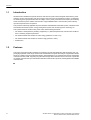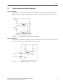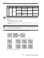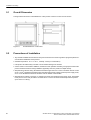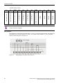
1
Preface
Content
SICAM P35
Overview
SICAM P36
Technical Data
3-phase Multi-Function
Power Meter
Functions
Operation and Display
V1.10
Manual
Installation and Wiring
Communication
Maintenance
Ordering Number
E50417-H8940-C562-2
1
2
3
4
5
6
7
8
Note
For safety purposes, please note instructions and warnings in the Preface.
Disclaimer of Liability
Copyright
We have checked the contents of this manual against the hardware
Copyright © Siemens AG 2014. Allrights reserved.
and software described. However, deviations from the description
Dissemination or reproduction of this document, or evaluation and
cannot be completely ruled out, so that no liability can be accepted
communication of its contents, is not authorized except where
expressly permitted. Violations are liable for damages. All rights
reserved, particularly for the purposes of patent application or
trademark registration.
for any errors or omissions contained in the information given.
The information given in this document is reviewed regularly and
any necessary corrections will be included in subsequent editions.
We appreciate any suggested improvements.
Registered Trademarks
We reserve the right to make technical improvements without
SIPROTEC, SINAUT, SICAM and DIGSI are registered trademarks
notice.
of Siemens AG. Other designations in this manual might be
trademarks whose use by third parties for their own purposes would
infringe the rights of the owner.
Document Version: V01.00.01
Release date: 2014.09
Siemens Ltd.
Order No.: E50417-H8940-C562-2
Preface
Purpose of this manual
This manual describes the functions, operation, installation, and commissioning of devices 3-phase Current
Power Meter-> In particular, one will find:
• Information regarding the configuration of the scope of the device and a description of the device functions
> Chapter 3;
• Instructions for Operation and Display > Chapter 4;
• Technical Data > Chapter 2;
Target Audience
Protection engineers, commissioning engineers, personnel concerned with adjustment, checking, and service
of selective protective equipment, automatic and control facilities, and personnel of electrical facilities and
power plants.
Additional Support
Should further information on the System SICAM be desired or should particular problems arise which are not
covered sufficiently for the purchaser's purpose, the matter should be referred to the local Siemens representative.
Our Customer Support Center provides a 24-hour service.
Phone: +49 (180) 524-8437
Fax: +49 (180) 524-2471
e-mail: [email protected]
Safety Information
This manual does not constitute a complete index of all required safety measures for operation of the equipment (module, device), as special operational conditions may require additional measures. However, it comprises important information that should be noted for purposes of personal safety as well as avoiding material
damage. Information that is highlighted by means of a warning triangle and according to the degree of danger,
is illustrated as follows.
DANGER!
Danger indicates that death, severe personal injury or substantial material damage will result if proper precautions are not taken.
WARNING!
Indicates that death, severe personal injury or substantial property damage may result if proper precautions
are not taken.
SICAM P35 P36, 3-phase Multi-Function Power Meter, User Manual
E50417-H8940-C562-2, Release Date 09.2014
3
Preface
Caution!
Indicates that minor personal injury or property damage may result if proper precautions are not taken. This
particularly applies to damage to or within the device itself and consequential damage thereof.
Note
Indicates information on the device, handling of the device, or the respective part of the instruction manual
which is important to be noted.
WARNING!
Qualified Personnel
Commissioning and operation of the equipment (module, device) as set out in this manual may only be carried
out by qualified personnel. Qualified personnel in terms of the technical safety information as set out in this
manual are persons who are authorized to commission, activate, to ground and to designate devices, systems
and electrical circuits in accordance with the safety standards.
Use as prescribed
The operational equipment (device, module) may only be used for such applications as set out in the catalogue
and the technical description, and only in combination with third-party equipment recommended or approved
by Siemens.
The successful and safe operation of the device is dependent on proper handling, storage, installation, operation, and maintenance.
When operating an electrical equipment, certain parts of the device are inevitably subject to dangerous voltage.
Severe personal injury or property damage may result if the device is not handled properly.
Before any connections are made, the device must be grounded to the ground terminal.
All circuit components connected to the voltage supply may be subject to dangerous voltage.
Dangerous voltage may be present in the device even after the power supply voltage has been removed (capacitors can still be charged).
Operational equipment with exposed current transformer circuits may not be operated.
The limit values as specified in this manual or in the operating instructions may not be exceeded. This aspect
must also be observed during testing and commissioning.
■
4
SICAM P35 P36, 3-phase Multi-Function Power Meter, User Manual
E50417-H8940-C562-2, Release Date 09.2014
Contents
1
2
Overview . . . . . . . . . . . . . . . . . . . . . . . . . . . . . . . . . . . . . . . . . . . . . . . . . . . . . . . . . . . . . . . . . . . . . . . . . . . . . . . .11
1.1
Introduction . . . . . . . . . . . . . . . . . . . . . . . . . . . . . . . . . . . . . . . . . . . . . . . . . . . . . . . . . . . . . . . . . . . . . .12
1.2
Features . . . . . . . . . . . . . . . . . . . . . . . . . . . . . . . . . . . . . . . . . . . . . . . . . . . . . . . . . . . . . . . . . . . . . . . 12
Technical Data . . . . . . . . . . . . . . . . . . . . . . . . . . . . . . . . . . . . . . . . . . . . . . . . . . . . . . . . . . . . . . . . . . . . . . . . . . .13
2.1
3
4
5
6
7
Functions . . . . . . . . . . . . . . . . . . . . . . . . . . . . . . . . . . . . . . . . . . . . . . . . . . . . . . . . . . . . . . . . . . . . . . . . . . . . . . .17
3.1
Measurement. . . . . . . . . . . . . . . . . . . . . . . . . . . . . . . . . . . . . . . . . . . . . . . . . . . . . . . . . . . . . . . . . . . . .18
3.2
Energy Metering . . . . . . . . . . . . . . . . . . . . . . . . . . . . . . . . . . . . . . . . . . . . . . . . . . . . . . . . . . . . . . . . . .18
3.3
Limit violation Alarm. . . . . . . . . . . . . . . . . . . . . . . . . . . . . . . . . . . . . . . . . . . . . . . . . . . . . . . . . . . . . . . .19
3.4
Display and Buttons . . . . . . . . . . . . . . . . . . . . . . . . . . . . . . . . . . . . . . . . . . . . . . . . . . . . . . . . . . . . . . .20
3.5
Communication . . . . . . . . . . . . . . . . . . . . . . . . . . . . . . . . . . . . . . . . . . . . . . . . . . . . . . . . . . . . . . . . . . .20
3.6
Permission and Security Management . . . . . . . . . . . . . . . . . . . . . . . . . . . . . . . . . . . . . . . . . . . . . . . . .20
3.7
Digital Input and Output Interface . . . . . . . . . . . . . . . . . . . . . . . . . . . . . . . . . . . . . . . . . . . . . . . . . . . . .21
Operation and Display . . . . . . . . . . . . . . . . . . . . . . . . . . . . . . . . . . . . . . . . . . . . . . . . . . . . . . . . . . . . . . . . . . . . .23
4.1
Full-screen Display . . . . . . . . . . . . . . . . . . . . . . . . . . . . . . . . . . . . . . . . . . . . . . . . . . . . . . . . . . . . . . . 24
4.2
Cyclic Display . . . . . . . . . . . . . . . . . . . . . . . . . . . . . . . . . . . . . . . . . . . . . . . . . . . . . . . . . . . . . . . . . . . .24
4.3
Key Definition. . . . . . . . . . . . . . . . . . . . . . . . . . . . . . . . . . . . . . . . . . . . . . . . . . . . . . . . . . . . . . . . . . . . .25
Installation and Wiring . . . . . . . . . . . . . . . . . . . . . . . . . . . . . . . . . . . . . . . . . . . . . . . . . . . . . . . . . . . . . . . . . . . .35
5.1
Overall Dimension . . . . . . . . . . . . . . . . . . . . . . . . . . . . . . . . . . . . . . . . . . . . . . . . . . . . . . . . . . . . . . . . 36
5.2
Precautions of Installation . . . . . . . . . . . . . . . . . . . . . . . . . . . . . . . . . . . . . . . . . . . . . . . . . . . . . . . . . . .36
5.3
Terminals and Wiring Diagram. . . . . . . . . . . . . . . . . . . . . . . . . . . . . . . . . . . . . . . . . . . . . . . . . . . . . . . .37
Communication . . . . . . . . . . . . . . . . . . . . . . . . . . . . . . . . . . . . . . . . . . . . . . . . . . . . . . . . . . . . . . . . . . . . . . . . . .41
6.1
Use of Communication . . . . . . . . . . . . . . . . . . . . . . . . . . . . . . . . . . . . . . . . . . . . . . . . . . . . . . . . . . . . .42
6.2
Introduction of MODBUS-RTU Communication Protocol . . . . . . . . . . . . . . . . . . . . . . . . . . . . . . . . . . .43
6.2.1
Overview . . . . . . . . . . . . . . . . . . . . . . . . . . . . . . . . . . . . . . . . . . . . . . . . . . . . . . . . . . . . . . . . . . . . .43
6.2.2
Function of Application Layer. . . . . . . . . . . . . . . . . . . . . . . . . . . . . . . . . . . . . . . . . . . . . . . . . . . . . .44
6.2.3
CRC Method . . . . . . . . . . . . . . . . . . . . . . . . . . . . . . . . . . . . . . . . . . . . . . . . . . . . . . . . . . . . . . . . . .45
6.2.4
Information mapping table . . . . . . . . . . . . . . . . . . . . . . . . . . . . . . . . . . . . . . . . . . . . . . . . . . . . . . . .46
Maintenance . . . . . . . . . . . . . . . . . . . . . . . . . . . . . . . . . . . . . . . . . . . . . . . . . . . . . . . . . . . . . . . . . . . . . . . . . . . . .53
7.1
8
Technical Data . . . . . . . . . . . . . . . . . . . . . . . . . . . . . . . . . . . . . . . . . . . . . . . . . . . . . . . . . . . . . . . . . . .14
Overview . . . . . . . . . . . . . . . . . . . . . . . . . . . . . . . . . . . . . . . . . . . . . . . . . . . . . . . . . . . . . . . . . . . . . . . .54
Ordering Number . . . . . . . . . . . . . . . . . . . . . . . . . . . . . . . . . . . . . . . . . . . . . . . . . . . . . . . . . . . . . . . . . . . . . . . . .55
8.1
Ordering Number . . . . . . . . . . . . . . . . . . . . . . . . . . . . . . . . . . . . . . . . . . . . . . . . . . . . . . . . . . . . . . . . .56
SICAM P35 P36, 3-phase Multi-Function Power Meter, User Manual
E50417-H8940-C562-2, Release Date 09.2014
5
Contents
6
SICAM P35 P36, 3-phase Multi-Function Power Meter, User Manual
E50417-H8940-C562-2, Release Date 09.2014
1
Overview
1.1
Introduction
12
1.2
Features
12
SICAM P35 P36, 3-phase Multi-Function Power Meter, User Manual
E50417-H8940-C562-2, Release Date 09.2014
11
Overview
1.1 Introduction
1.1
Introduction
SICAM P35 and SICAM P36 3-phase electronic multi-function power meters integrate measurement, power
metering, remote communication and control, large screen LCD and communication functions. It is designed
for measuring power grid parameters such as voltage, current, power, power factor and frequency and metering
active and reactive power. RS485 communication support MODBUS-RTU communication protocol. Binary
input and output functions are optional.
This product is extensively applicable to power substation and distribution automation system, industrial control
and industrial automation system, energy management system and community power monitoring, etc.
This 3-phase electronic multi-function power meter meets following standards:
• IEC 62052-11:2003 (Electricity metering equipment (a.c.) General requirements, tests and test conditionsPart 11: Metering equipment) standard
• IEC 62053-22:2003 static meters for active energy (classes 0.2 S and 0.5 S)
• IEC 62053-23:2003 static meters for reactive energy (classes 2 and 3)
• Modbus-RTU
1.2
Features
This project uses high-precision sampling and metering unit and high-speed MCU data processing unit, supporting high-precision, wide-range and accurate measurement and quick data analysis; segmented multi-line
WVA LCD, realizing various and abundant display; white backlight for LCD, satisfying the need for viewing data
in dark environment; NVM, supporting long-time data storage without data loss even in the event of power failure; RS485 communication port and industrial standard communication protocols, realizing flexible and reliable
communication.
■
12
SICAM P35 P36, 3-phase Multi-Function Power Meter, User Manual
E50417-H8940-C562-2, Release Date 09.2014
Technical Data
2.1
Technical Data
SICAM P35 P36, 3-phase Multi-Function Power Meter, User Manual
E50417-H8940-C562-2, Release Date 09.2014
2
14
13
Technical Data
2.1 Technical Data
2.1
Technical Data
Item
Technical Data
Product standard
IEC61557-12:2007
Input connection
3-phase-3-wire, 3-phase-4-wire, single phase
Reference voltage Un: AC380 V, AC220 V, AC100 V,
AC57.7 V
Measuring range: 10 V ... 264 V phase voltage
Voltage
Maximum measuring range: 400 V phase voltage
Power consumption: < 0.05 VA (single phase)
Accuracy: RMS 0.2%
Resolution: 0.01 V
Rated current In: 1 A, 5 A
Measuring range: 0.015 A ... 6 A
Measurement
Current
Maximum measuring range: 9 A
Power consumption: < 0.05 VA (single rated current)
Accuracy: RMS 0.2%
Resolution: 0.001 A
Power
(active, reactive, apparent)
Accuracy: 0.2%
Resolution: 0.001 kW/kVar/kVA
Measuring range: 45 Hz ... 65 Hz
Power grid frequency
Accuracy: 0.2%
Resolution: 0.01 Hz
Active power
Metering
Reactive power
Power pulse output
Accuracy level: 0.5 S, Acc. To IEC 62053-22
Resolution: 0.01 kWh, 5000 imp/kWh
Accuracy: Class 2, Acc. To IEC 62053-23
Resolution: 0.01 kvarh, 5000 imp/kvarh
2 electric energy (active and reactive) pulse outputs
Opto-coupler isolation, 4,000 VRMS
2 electromagnetic relay output
Digital signal
Binary output (optional) Normal Open Contact
Contact capacity: AC 250 V /3 A, DC 30 V /3 A
Binary input (optional)
4 dry contact inputs
Opto-coupler isolation, 4,000 VRMS
Interface type: Twisted Pair, Half Duplex Transmission
Communication
RS-485 port
Communication rate: 600 bps ... 38,400 bps
Protocol: Modbus-RTU
Environment
14
Operating temp.
-25 ℃ ... +60 ℃
Operating temp. limit
-35 ℃ ... +70 ℃
Relative humidity
≤ 95% (condensation free)
SICAM P35 P36, 3-phase Multi-Function Power Meter, User Manual
E50417-H8940-C562-2, Release Date 09.2014
Technical Data
2.1 Technical Data
Item
Operating power
supply
Others
Dimension
Weight
Technical Data
AC or DC power supply
Max. input range: 40 V ... 420 V
Power consumption: ≤ 1 W, 2 VA
Overall dimension (mm): 96×96×95
Panel cut out size (mm): 92×92
Approx. 450 g
■
SICAM P35 P36, 3-phase Multi-Function Power Meter, User Manual
E50417-H8940-C562-2, Release Date 09.2014
15
Technical Data
2.1 Technical Data
16
SICAM P35 P36, 3-phase Multi-Function Power Meter, User Manual
E50417-H8940-C562-2, Release Date 09.2014
3
Functions
3.1
Measurement
18
3.2
Energy Metering
18
3.3
Limit violation Alarm
19
3.4
Display and Buttons
20
3.5
Communication
20
3.6
Permission and Security Management
20
3.7
Digital Input and Output Interface
21
SICAM P35 P36, 3-phase Multi-Function Power Meter, User Manual
E50417-H8940-C562-2, Release Date 09.2014
17
Functions
3.1 Measurement
3.1
Measurement
This meter is provided with various measuring functions. Power grid parameters and index measurable are as
follows:
• voltage of each phase and mean voltage
• voltage of each line and mean voltage
• current of each phase, average current and neutral current
• overall and separate active power, reactive power and apparent power of each phase
• phase angle of voltage and current of each phase
• overall and separate power factor of each phase
• power grid frequency and measuring range 45Hz to 65 Hz
3.2
Energy Metering
This meter can meter various energy data:
• combined active and supply and demand active energy
• combined reactive and four-quadrant reactive energy
• supply and demand active energy of each phase and combined reactive energy of each phase
18
SICAM P35 P36, 3-phase Multi-Function Power Meter, User Manual
E50417-H8940-C562-2, Release Date 09.2014
Functions
3.3 Limit violation Alarm
3.3
Limit violation Alarm
1. This product is provided with limit violation alarm function. User may select from voltage, current, power,
power factor and frequency parameters at most 6 data groups at the same time as detection object and set
upper and lower limits and judgment condition for them. Alarm will be activated when measured value is over
the set limit. This product is provided with 2 relay outputs. When alarm parameters are configured that output
is made from certain relay which is at automatic mode (not manual), limit violation alarm signal can be output
through such relay (relay closing).
2. At most 6 limit violation alarm parameters can be set at the same time within the product. Configuration flow
of each limit violation alarm parameter: select type of detected data-set threshold of detected data-set
judgment condition-select output relay for alarm signal.
• Code of various detected data: (hexadecimal number for Modbus-RTU code)
MODBUS code
00
Content of data
MODBUS code
Content of data
Phase A power factor
14
Phase A active power
01
Phase B power factor
15
Phase B active power
02
Phase C power factor
16
Phase C active power
03
Total power factor
17
Total active power
06
Frequency
18
Phase A reactive power
07
Phase A voltage
19
Phase B reactive power
08
Phase B voltage
1A
Phase C reactive power
09
Phase C voltage
1B
Total reactive power
0B
Uab line voltage
1C
Phase A apparent power
0C
Ubc line voltage
1D
Phase B apparent power
0D
Uca line voltage
1E
Phase C apparent power
0F
Phase A current
1F
Total phase apparent power
10
Phase B current
11
Phase C current
12
Neutral current
When code of detected data is FF, limit violation alarm function of such group is off.
• Threshold of detected data: threshold judging whether detected value is out of limit; Different units for
different data types: such as voltage-V, current-A, active-KW, reactive power-KVAR, apparent-KVA,
frequency-Hz.
• Judging condition: 0 means alarm activated when exceeding limit; 1 means alarm activated when falling
below limit.
• Alarm signal output relay: 0 means no alarm signal output; 1 means alarm signal outputted from relay1;2
means alarm signal outputted from relay 2; 3 means alarm signal outputted from relay 1 and relay 2 at the
same time. .
3. Example of alarm parameter setting. Set one limit violation alarm parameter to automatic detection and alarm
for "Phase A voltage", assuming that alarm threshold is 240 V, judging criterion is "over limit” and signal is
outputted from relay 2.
Use MODBUS RTU protocol to set alarm parameter: set 0110 address to "07", 0111 to "0000", 0112 to
"5DC0" (multiply "240" by 100 to generate "24,000" and convert it into "00005DC0"), 0113 to "00" and 0114
to "02".
SICAM P35 P36, 3-phase Multi-Function Power Meter, User Manual
E50417-H8940-C562-2, Release Date 09.2014
19
Functions
3.4 Display and Buttons
3.4
Display and Buttons
This product uses large-screen WVA multi-line LCD to provide visual and various display. The screen is
provided with white backlight, enabling clear display in dark environment. Specific data information can be
obtained through display with button operation. For details, see Chapter Operation and Display.
3.5
Communication
RS485 port is provided for parameter setting and reading of various data. For specific description, see Chapter
Communication.
3.6
Permission and Security Management
1. This product is provided with programming permission management function.
• L0 password: used for meter reset, setting all parameters and modifying L0, L2 and L4 passwords;
• L2 password: used for meter reset, setting all parameters and modifying L2 and L4 passwords;
• L4 password: used for parameter setting and modifying L4 password, not for meter reset, clearing extreme
values and PT/CT ratio setting.
• All level default PASSWORD is "000000"
2. Parameter setting is available only when this product is in programmable state. Steps for entering
programming state: press "
" and "
" at the same time to enter "PASS" screen; input correct
password and press "
" to enter "SET" screen and enable programmable state. After entering
programmable state, programmable state prompt appears on the bottom right corner of LCD. Programmable
state will remain valid in 10 minutes after program button is pressed and become invalid after power down.
3. If incorrect password is used to set this product continuously (including communication setting and button
programming) up to specific number of times (factory default 5 times), parameter setting function will be
locked (factory default 60 minutes). Error count will be reset after setting once using correct password if such
count is less than specific limit. Error count of password and lock time can be set (available in factory state).
20
SICAM P35 P36, 3-phase Multi-Function Power Meter, User Manual
E50417-H8940-C562-2, Release Date 09.2014
Functions
3.7 Digital Input and Output Interface
3.7
Digital Input and Output Interface
Power Pulse Output
This meter provides two power pulse outputs: active and reactive, with internal opto-isolation, pulse output
width (80±20) ms, maximum allowable passing current 10 mA (DC) and operating voltage range 5 V to 80 V
(DC).
Figure 3-1
Circuit Diagram of Power Pulse Output Interface
Binary Input Interface
This product is provided with 4-digit binary inputs interface based on passive dry contact. Terminals are identified as DI1, DI2, DI3, DI4 and COM. COM is the common terminal.
Figure 3-2
Circuit Diagram of Binary Input Interface
SICAM P35 P36, 3-phase Multi-Function Power Meter, User Manual
E50417-H8940-C562-2, Release Date 09.2014
21
Functions
3.7 Digital Input and Output Interface
Relay Output Interface
This product is provided with two relay outputs interfaces for alarm indication or protection control output in
many conditions. Electric parameter of internal relay: AC 250 V/DC 30 V, 3 A.
Figure 3-3
Circuit Diagram of Relay Output Interface
■
22
SICAM P35 P36, 3-phase Multi-Function Power Meter, User Manual
E50417-H8940-C562-2, Release Date 09.2014
Operation and Display
4
4.1
Full-screen Display
24
4.2
Cyclic Display
24
4.3
Key Definition
25
SICAM P35 P36, 3-phase Multi-Function Power Meter, User Manual
E50417-H8940-C562-2, Release Date 09.2014
23
Operation and Display
4.1 Full-screen Display
4.1
Full-screen Display
Figure 4-1
4.2
Description of LCD Indication
Cyclic Display
Key Functions at Cyclic Display Mode
Key symbol
Function
▲
▼
Switching from cyclic display to
buttom display
Lock/unlock blinking
display
Switching between display
areas A and B (blinking
prompt)
Screen Lock in Cyclic Display State
Data in display area A or B can be locked in cyclic display state to enable long-time monitoring of data in certain
area.
Steps: press "
", select the desired display area (target data will blink thrice), and press "
vice versa for unlocking.
" to lock, and
Cyclic Display Parameter
Duration: 1 to 99 sec., configurable;
Number of items: to be defined with one byte. 4 high 4 bits are number of items in display area A while 4 low 4
bits are number of items in display area B. 16 items are acceptable to each area. At any time, display area A
and display area B should have at least one cyclic display item.
Cyclic Display State
Cyclic display data in areas A and B can be defined by user. User may develop cyclic display scheme previously
through inquiring "Code list of optional settings in areas A and B".
Code list of optional settings in area A:
Data item
24
Data type (current value)
Transient
Maximun
Minimum
Phase voltage
0
1
2
Line voltage
3
4
5
Current
6
7
8
Neutral current
9
10
11
SICAM P35 P36, 3-phase Multi-Function Power Meter, User Manual
E50417-H8940-C562-2, Release Date 09.2014
Operation and Display
4.3 Key Definition
Data item
Data type (current value)
Transient
Maximun
Minimum
Active power
12
13
14
Reactive power
15
16
17
Apparent power
18
19
20
Power factor
21
/
/
Phase angle
22
/
/
Code list of optional settings in area B:
Data item
Data type (current value)
Transient
Data item
Maximun Minimum
Data
Current
month
Phase
L1
Phase
L2
Phase
L3
Average phase
voltage
228
229
230
Import active
power
251
252
253
254
Average line
voltage
231
232
233
Export active
power
255
256
257
258
Average current
234
235
236
Total active
power
259
260
261
262
Neutral current
237
238
239
Net active
power
263
264
265
266
Total active power
240
241
242
Impot reactive
power
267
268
269
270
Total reactive
power
243
244
245
Export reactive
power
271
272
273
274
Total apparent
power
246
247
248
Total reactive
power
275
276
277
278
Total power factor
249
/
/
Net reactive
power
279
280
281
282
Frequency
250
/
Error code
283
/
Note
In flip-with-key state or parameter-set-with-key state, this product will automatically return to cyclic display state
if no key operation within defined duration.
4.3
Key Definition
Key Functions at Flip-With-Key Display Mode
Key symbol
Function
▲
▼
1) Switch from cyclic display state
to key display state through pressing "▲" or "▼".
2) Flip over to previous screen with
"▲" and to next screen with "▼".
SICAM P35 P36, 3-phase Multi-Function Power Meter, User Manual
E50417-H8940-C562-2, Release Date 09.2014
Enter next menu
1) Switch between A (multiline) and B (single line) display
areas
2) Return to previous menu
25
Operation and Display
4.3 Key Definition
Data Item of Key Display
• Data items displayed in area A (mainly measuring data)
Level 1
Level 2
Voltage (1)
Extreme value
Line voltage (2)
Extreme value
Current (3)
Extreme value
Neutral current (4)
Extreme value
Active power (5)
Extreme value
Reactive power (6)
Extreme value
Apparent power (7)
Extreme value
Power factor (8)
/
Phase angle (9)
/
PT and CT ratio (10)
/
• Data items displayed in area B (mainly measuring data)
Electric energy
Import
active
Export
active
Total
active
Net active
Total
(01)
(05)
(09)
(13)
(17)
(21)
(25)
(29)
Phase
A
(02)
(06)
(10)
(14)
(18)
(22)
(26)
(30)
Phase
B
(03)
(07)
(11)
(15)
(19)
(23)
(27)
(31)
Phase
C
(04)
(08)
(12)
(16)
(20)
(24)
(28)
(32)
Frequency
(33)
Version
(34)
Active constant
(35)
Reactive
constant
(36)
Device ID
(37)
Error code
(38)
Import re- Export re- Total reac- Net reacactive
active
tive
tive
• Data items combined in area A and B:
Firmware version number, Device ID, active constant and reactive constant.
Note
Full screen, firmware version number is displayed in order when the meter is power on.
26
SICAM P35 P36, 3-phase Multi-Function Power Meter, User Manual
E50417-H8940-C562-2, Release Date 09.2014
Operation and Display
4.3 Key Definition
Examples for Flip-With-Key Operation
Example 1:
This screen shows voltage items.
At cyclic display mode, press "▲" or "▼" to enter key display
mode. When area A is selected, press "▲" or "▼" again to
switch to voltage items.
In the figure, L1=220.0 V, L2=220.1 V, L3=220.5 V and 3phase average voltage=220.2 V.
"RS1" shows there is one RS485 port and flickering symbol
means communication in progress. "
" means the meter
runs in first quartile.
Example 2:
This screen shows maximum value display items of current
line voltage.
At cyclic display mode, press "▲" or "▼" to enter key display
mode. When area A is selected, press "▲" or "▼" again to
switch to voltage items and press "
" to enter maximum
value display.
In the figure: L1=380.0 V, L2=380.1 V, L3=380.5 V, and
maximum 3-phase average line voltage=380.2 V. You can
press "▲" or "▼" to switch to minimum line voltage display.
Press "
" to return to previous display.
Example 3:
This screen shows current items.
At cyclic display mode, press "▲" or "▼" to enter key display
mode. When area A is selected, press "▲" or "▼" to switch to
phase current display.
In the figure, L1=1.000 A, L2=1.001 A, L3=1.002 A and 3phase average current=1.001 A.
Example 4:
This screen shows zero sequence current items.
At cyclic display mode, press "▲" or "▼" to enter key display
mode. When area A is selected, press "▲" or "▼" to enter
zero sequence current display mode.
In the figure, L1=0.940 A, L2=1.003 A, L3=1.006 A and zero
sequence current=0.079 A.
SICAM P35 P36, 3-phase Multi-Function Power Meter, User Manual
E50417-H8940-C562-2, Release Date 09.2014
27
Operation and Display
4.3 Key Definition
Example 5:
This screen shows current active power items.
At cyclic display mode, press "▲" or "▼" to enter key display
mode. When area A is selected, press "▲" or "▼" to enter
active power items.
In the figure, L1=1.020 kW, L2=1.061 kW, L3=1.042 kW and
total active power=3.123 kW.
Example 6:
This screen shows current reactive power items.
At cyclic display mode, press "▲" or "▼" to enter key display
mode. When area A is selected, press "▲" or "▼" to enter reactive power items.
In the figure, L1=0.320 kvar, L2=0.351 kvar, L3=0.322 kvar
and total reactive power=0.993 kvar.
Example 7:
This screen shows current apparent power items.
At cyclic display mode, press "▲" or "▼" to enter key display
mode. When area A is selected, press "▲" or "▼" to enter apparent power items.
In the figure, L1=1.210 kVA, L2=1.168 kVA, L3=1.174 kVA and
total apparent power=3.552 kVA.
Example 8:
This screen shows current power factor items.
At cyclic display mode, press "▲" or "▼" to enter key display
mode. When area A is selected, press "▲" or "▼" to enter
power factor items.
In the figure, L1=1.000, L2=0.999, L3=1.000 and total power
factor=1.000.
Example 9:
This screen shows phase angle items.
At cyclic display mode, press "▲" or "▼" to enter key display
mode. When area A is selected, press "▲" or "▼" to enter
phase angle items.
In the figure, L1=30.0°, L2=30.2°, L3=31.0°.
28
SICAM P35 P36, 3-phase Multi-Function Power Meter, User Manual
E50417-H8940-C562-2, Release Date 09.2014
Operation and Display
4.3 Key Definition
Example 10:
This screen shows PT and CT ratio display items.
At cyclic display mode, press "▲" or "▼" to enter key display
mode. When area A is selected, press "▲" or "▼" to enter PT
and CT ratio display items.
In the figure, PT ratio=20.0, CT ratio=5.0.
(Note: decimals part of ratio are not displayed.)
Example 11:
This screen shows current Phase B total active power items.
At cyclic display mode, press "▲" or "▼" to enter key display
mode, press "
" to switch to area B, and press "▲" or "▼"
to switch to current Phase B total active power items.
Example 12:
This screen shows frequency display items.
At cyclic display mode, press "▲" or "▼" to enter key display
mode, press "
" to switch to area B, and press "▲" or "▼"
to switch to frequency items, namely frequency value.
Example 13:
This screen shows display items of software version.
At cyclic display mode, press "▲" or "▼" to enter key display
mode. Press "
" to switch to area B. Press "▲" or "▼"
again to switch to display items of software version.
In the figure, "Soft" means software version, "13" means
product specification, "121121" means software version date
and "00" means serial number of software production.
Example 14:
This screen shows active pulse constant items.
At cyclic display mode, press "▲" or "▼" to enter key display
mode, press "
" to switch to area B, and press "▲" or "▼"
to switch to active pulse constant items.
In the figure, active constant=5,000 imp/kWh.
SICAM P35 P36, 3-phase Multi-Function Power Meter, User Manual
E50417-H8940-C562-2, Release Date 09.2014
29
Operation and Display
4.3 Key Definition
Example 15:
This screen shows reactive pulse constant items.
At cyclic display mode, press "▲" or "▼" to enter key display
mode, press "
" to switch to area B, and press "▲" or "▼"
to switch to reactive pulse constant items.
In the figure, reactive constant=5,000 imp/kWh.
Example 16:
This screen shows Device ID display items.
At cyclic display mode, press "▲" or "▼" to enter key display
mode, press "
" to switch to area B, and press "▲" or "▼"
to switch to Device ID display items. Device
ID=000000000001.
Example 17:
This screen shows error code display items.
At cyclic display mode, press "▲" or "▼" to enter key display
mode, press "
" to switch to area B. Press "▲" or "▼" again
to switch to fault code display items. "E" means fault prompt,
the 7 bits from right to left mean respectively phase A loss,
phase B loss, phase C loss, voltage phase inversion, phase C
reverse, phase B reverse, and phase A reverse. For example,
"E0110001" means phase B and phase C loss and phase C
reverse fault occurs.
Key Setting Parameters
1. Key functions at parameter setting mode
Key symbol
▲
▼
a) Press "
" and "
setting screen.
Function
a) "▲" to switch digit or flip over;
b) Press "
b) "▼" to move cursor or flip over. setting.
" at the same time to enter
" to enter next menu or "confirm" parameter
c) Press "
" to return to previous menu or "cancel" parameter setting 1.
1.Press "
" once after adjusting parameters with "▲" and "▼" to display "Sure", and press "
" once
again to alter parameters. Pressing "
" immediately after "Sure" appears will cancel current alteration.
30
SICAM P35 P36, 3-phase Multi-Function Power Meter, User Manual
E50417-H8940-C562-2, Release Date 09.2014
Operation and Display
4.3 Key Definition
2. Data items configurable with key (Note 1)
NO.
1st level menu
Symbol
Definition
2nd level menu
Symbol
Definition
Baud rate
Parity
1
2
Communication
setting
Ratio
setting
(Note 2)
Range
600 ... 38400
Modbus address
0 ... 247
Modbus sending
delay
0 ... 2999
DL/T645 high 6
address
0 ... 999999
Default setting: 0
DL/T645 low 6
address
0 ... 999999
Default setting:
Last 3 digital of S/N
Default setting: 0
Unit: ms
Default setting: 10
Voltage ratio
integer part
0 ... 9999
Voltage ratio
decimal part
Combination 0 ...
9999.9999
0 ... 9999
Default setting: 1
Current ratio
integer part
0 ... 9999
Combination 0 ...
9999.9999
Current ratio
decimal part
0 ... 9999
Connection
System
setting
Default setting: 1
3phase4wire
3P3L_2CT
3phase3wire -2CT
3P3L_3CT
3phase3wire -3CT
AUto
Password
4
Default setting:
2400
8E1/8o1/8n1/8n Default setting:
2
8E1
3P4L
3
Remarks
Automatic
6 bits in total, Set
L0-2 password
Default setting:
000000
Clearing
extreme
value
Meter reset
SICAM P35 P36, 3-phase Multi-Function Power Meter, User Manual
E50417-H8940-C562-2, Release Date 09.2014
31
Operation and Display
4.3 Key Definition
NO.
1st level menu
Symbol
5
Definition
2nd level menu
Symbol
Display
setting
Definition
Range
Time of returning to
cyclic display state
when no operation
1 ... 99
Time of backlight
on when no operation (normally on
when set to 0)
0 ... 99
Interval of cyclic
display
1 ... 99
Remarks
Unit: min.
Default setting: 10
Unit: min.
Default setting: 10
Unit: sec
Default setting: 5
Note
Password level (1 bit, 0 to 2) and password (6 bits) should be entered at first for key setting. Password level
and permission:
• L0 password-all parameters above are configurable;
• L1 password-all parameters above are configurable;
• L2 password-all parameters except for meter reset, clearing extreme value and PT/CT conversion ratio are
configurable.
Note
The meter should be reset after altering PT/CT ratio to ensure reasonable correspondence between
communication reading and displayed metering data.
3. Parameter setting with keys (take "Conn communication setting" for example)
Figure 4-2
32
Parameter setting with keys
SICAM P35 P36, 3-phase Multi-Function Power Meter, User Manual
E50417-H8940-C562-2, Release Date 09.2014
Operation and Display
4.3 Key Definition
At any time, press "
" and "
" simultaneously to enter "PASS" screen. The first digit of displayed data
means password level and the remaining 6 data make up the password (press "▲" to change digits and "▼"
to move cursor). Press "
" to confirm. "FAIL" will appear if password level and password are wrong. To reenter password, press "
". To quit and return to cyclic display state, enter "
" (if specified error count is
reached, parameter setting function will be locked for certain period which is configurable in advance). If is
password is validated, you may enter the first level menu. The figure shows the read-write items under "Conn"
menu: baud rate and communication address of RS485 port can be set.
Note
"SURE" screen appears after selecting or inputting parameter and pressing "
". Press "
" once
again to activate new parameter. Pressing "
" at any time during parameter setting will cancel setting or
return to previous menu.
■
SICAM P35 P36, 3-phase Multi-Function Power Meter, User Manual
E50417-H8940-C562-2, Release Date 09.2014
33
Operation and Display
4.3 Key Definition
34
SICAM P35 P36, 3-phase Multi-Function Power Meter, User Manual
E50417-H8940-C562-2, Release Date 09.2014
Installation and Wiring
5
5.1
Overall Dimension
36
5.2
Precautions of Installation
36
5.3
Terminals and Wiring Diagram
37
SICAM P35 P36, 3-phase Multi-Function Power Meter, User Manual
E50417-H8940-C562-2, Release Date 09.2014
35
Installation and Wiring
5.1 Overall Dimension
5.1
Overall Dimension
The figure below shows the overall dimension of this product. Panel cut out size: 92 mm×92 mm
Figure 5-1
5.2
Overall Dimension of Instrument
Precautions of Installation
1. Dry and well ventilated environment far away from thermal source and strong electric (magnetic) field is recommended for installation of this product.
2. Ambient temperature: -25 ℃ to +60 ℃ , humidity: ≤ 95% (no condensation)
3. This product should be firmly mounted to avoid accident arising from vibration.
4. For the reason of convenient installation, maintenance and operation and safety, enough space around this
product should be reserved during installation (especially when one panel for multiple meters).
5. Requirement for electric wiring: Stranded fire-retarded copper wire over 2.5 mm2 should be used for current
circuit, 1.5 mm2 stranded fire-retarded copper wire should be used for voltage circuit and power supply circuit,
and 1.0 mm2 Shielded Twisted Pair should be used for RS485 communication.
6. Requirement for electric connection: In voltage input circuit and operating power supply circuit, appropriate
fuses (such as 0.5 A fuse) should be connected and a CT short-circuit box should be provided to prevent
open circuit of CT wiring.
36
SICAM P35 P36, 3-phase Multi-Function Power Meter, User Manual
E50417-H8940-C562-2, Release Date 09.2014
Installation and Wiring
5.3 Terminals and Wiring Diagram
5.3
Terminals and Wiring Diagram
Definition of Terminals (viewed from rear to front and from left to right)
1. Upper main terminals
V+
V-
NC
NC
R11
R12
R21
R22
Relay output 2
Relay output 1
Reserved
Reserved
Power supply
Note
NC means no connection, the same below.
2. Lower main terminals
V1
V2
V3
VN
I11
I12
I21
I22
I31
I32
Phase A voltage
Phase B voltage
Phase C voltage
Neutral
Phase A current input
Phase A current output
Phase B current input
Phase B current output
Phase C current input
Phase C current output
Note
Main terminals are barrier terminals which can be connected using fork or ring type lug (no more than 6.5 mm
wide). For cables to be connected to upper and lower main terminals, cold-pressed UT2.5-3 terminal is
recommended before connection. The diagram of connection is below.
Figure 5-2
Connection Diagram of Main Terminal
SICAM P35 P36, 3-phase Multi-Function Power Meter, User Manual
E50417-H8940-C562-2, Release Date 09.2014
37
Installation and Wiring
5.3 Terminals and Wiring Diagram
3. Middle auxiliary terminal
Binary input 3
A
B
NC
NC
Reserved
Binary input 2
COM2
Reserved
Binary input 1
DI4
RS485 -
DI3
RS485 +
DI2
Common binary input terminal
DI1
Binary input 4
COM1
Common pulse output terminal
Active pulse output
Q+
Reactive pulse output
P+
Note
Auxiliary terminal is pluggable.
Wiring Diagram
Wiring diagram of main terminal is showed below. "V+" and "V-" are power supply terminals. This product supports DC/AC input, with input voltage 40 V to 420 V. For 3-phase-3-wire connection, Vn and V2 should be
subject to external pup joint, see Figure 5-5.
Figure 5-3
38
Wiring Diagram of 3-phase-4-wire (W/O PT)
SICAM P35 P36, 3-phase Multi-Function Power Meter, User Manual
E50417-H8940-C562-2, Release Date 09.2014
Installation and Wiring
5.3 Terminals and Wiring Diagram
Figure 5-4
Wiring Diagram of 3-phase-4-wire (With PT)
Figure 5-5
Wiring Diagram of 3-phase-3-wire
■
SICAM P35 P36, 3-phase Multi-Function Power Meter, User Manual
E50417-H8940-C562-2, Release Date 09.2014
39
Installation and Wiring
5.3 Terminals and Wiring Diagram
40
SICAM P35 P36, 3-phase Multi-Function Power Meter, User Manual
E50417-H8940-C562-2, Release Date 09.2014
Communication
6
6.1
Use of Communication
42
6.2
Introduction of MODBUS-RTU Communication Protocol
43
SICAM P35 P36, 3-phase Multi-Function Power Meter, User Manual
E50417-H8940-C562-2, Release Date 09.2014
41
Communication
6.1 Use of Communication
6.1
Use of Communication
RS485 port of this product supports MODBUS-RTU communication protocol. Even parity check is the default
setting for data byte check, namely 8E1 (8 digit data, even parity check, 1 stop bit) format. MODBUS-RTU communication protocol can also be configured to odd parity check or no verification, namely 8O1 (8 digit data, odd
parity check, 1 stop bit), 8N1 (8 digit data, no parity check, 1 stop bit), or 8N2 (8 digit data, no parity check, 2
stop bits) format. Baud rate of communication port could any of 600 bps, 1,200 bps, 2,400 bps, 4,800 bps, 9,600
bps, 19,200 bps and 38,400 bps.
RS485 port of this product should be connected using Shield Twisted Pair. When wiring, layout of the entire
network should be considered: length and orientation of communication cable, position of upper computer,
matched resistance at network end-point, communication converter, network scalability, network coverage,
EMI, etc.
Note
1. Wiring should be conducted strictly in accordance with requirement.
2. The power meter requiring no communication temporarily should be connected to RS485 network for easy
diagnosis and test.
3. The shielding layer side of cable connected with upper computer should be reliably earthed (PGND: ground,
cubicle, cabinet, etc.) to avoid two-point or multi-point earthing.
4. Shield Twisted Pair should be used for RS485 bus cable. For two twisted pairs, different colors are recommended, one color for "A" side and another color for "B" side of 485 communication port.
42
SICAM P35 P36, 3-phase Multi-Function Power Meter, User Manual
E50417-H8940-C562-2, Release Date 09.2014
Communication
6.2 Introduction of MODBUS-RTU Communication Protocol
6.2
Introduction of MODBUS-RTU Communication Protocol
6.2.1
Overview
Type of Protocol
This is MODBUS RTU protocol applicable to real-time communication of embedded electric energy meter. This
protocol defines the data exchange between terminal unit (slave) and Master, which is realized in the form of
RTU (remote terminal unit) of MODBUS. Asynchronous master-slave half-duplex communication is used.
Communication is initiated from master and slave responds after receiving request from master.
Communication response time < 0.2 sec.
Physical Layer
• Transmission interface: RS485
• Communication address: 0 to 247
• Communication baud rate: 600 bps to 38,400 bps
• Communication media: Shield Twisted Pair
Data Link Layer (DLL)
• Transmission manner: asynchronous master-slave half-duplex
• Data frame format: 1 start bit, 8 digit data, even parity check bit, 1 stop bit
• Data packet format:
Address
8 bits
Function
Data
CRC
8 bits
n*8 bits
16 bits
Data packet transmission sequence always uses identical address, function code, data and check code. Each
data packet should be transmitted as a continuous bit stream. When data packet from the master reaches
slave, slave matching the address field in data packet will receive and check the data. If no error, slave will
execute the request in data packet and send the responsive date packet to the master. The data packet sent
back by slave contains slave Address, Function executed, Data generated from function execution and CRC.
• Address
Address is at the beginning of data packet and consists of an 8-bit data which means slave address specified
by the master. Each slave address in the bus is unique. Valid address range is from 0 to 247. After the master
sends data packet, only slave matching the inquire address of the master will respond.
• Function
It describes which function is executed by slave. Meanings of all function codes are given below.
Code
Definition
Function
03 H
Read data
Read current binary value of one or more variables
10 H
Preset multiple registers
Overwrite values of several variables using specific binary value
• Data
It contains data required for executing specific function by slave or data acquired when slave responds inquiry
of master. Content of these data may be address code or data.
• CRC
Check code is 16-bit check data formed in data transmission for CRC of master and slave. Various
interferences exist in communication, so data transmitted during communication may change. CRC will avoid
data distortion during responsive transmission of master and slave and improves security and efficiency of
system. For formation rule of check code, see Annex 1.
SICAM P35 P36, 3-phase Multi-Function Power Meter, User Manual
E50417-H8940-C562-2, Release Date 09.2014
43
Communication
6.2.2 Function of Application Layer
6.2.2
Function of Application Layer
Read Data Command (function code 03 H)
• Down frame format
Communication
address (0-247)
Function
code
(03 H)
High byte of
start address
of data
Low byte of
start address
of data
High byte
of length
of data
Low byte of
length of
data
Low byte High byte
of CRC
of CRC
• Response frame format
Communication
address (0-247)
Function Number of
code
bytes of data
length
(03 H)
Content of
data
Content of
data
Content of Low byte of High byte of
data
CRC
CRC
• Example
- Down frame of 3-phase voltage data read
Device address
03 H
10 H
00 H
00 H
03 H
Low check
High check
06 H
Data 1
Data 2
...
Low check
High check
- Response frame
Device address
03 H
Preset Multi-Register Command (function code 10 H)
• Down frame format
Device
address
0-247
•
Function
code
(10 H)
High byte Low byte
High byte
Low
of start
of start
Byte
of varibyte of
address address
n of
able
variable
of variof varidata
number number
able
able
Byte
1 of
data
Byte
of
data
Byte
n of
data
Low
High
byte of byte of
CRC
CRC
Response frame format
Device
address
0-247
Function
code
(10 H)
High
Low byte
byte of
of start
start
address
address
of variof variable
able
High
byte of
variable
number
Low
byte of Low byte
variable of CRC
number
High
byte of
CRC
• Example
- Down frame when PT conversion ratio is 1234.5678 (hexadecimal notation of 12345678: 00BC 614EH)
Device
address
10 H
00 H
03 H
00 H
02 H
04 H
00 H BC H 61 H 4E H Low check High check
- Response frame
Device address
44
10 H
00 H
03 H
00 H
02 H
Low check
High check
SICAM P35 P36, 3-phase Multi-Function Power Meter, User Manual
E50417-H8940-C562-2, Release Date 09.2014
Communication
6.2.3 CRC Method
Exception Response
• Exception response frame format
Function code
Communication
address (0-247)
Exception code
(XX H)
(80 H+03 H)
Low byte of
CRC
High byte of
CRC
(80 H+10 H)
• Example
- Address data of illegal register read
Device address
03 H
XX H
83 H
02 H
XX H
00 H
01 H
Low check
High check
- Response frame
Device address
Low check
High check
• Exception code of MODBUS
6.2.3
Code
Meaning
02 H
Illegal data address
03 H
Illegal data
10 H
No permission
11 H
Register length overflow
CRC Method
CRC contains 2 bytes, namely 16-bit binary system. CRC is calculated with transmitting device and placed at
the tail of transmitted message. Receiving device recalculates CRC of message received and compares
whether CRC derived matches the received one. If not, error may occur.
To calculate CRC, preset all 16-bit registers to 1. Then, process each 8-bit data message one by one. Only 8bit data bit is used for CRC calculation and start bit and stop bit and parity check bit (if any) are not involved.
Steps of calculating CRC:
• Preset 16-bit register to hexadecimal FFFF (namely all to 1), and this register is called CRC register.
• Execute exclusive OR of low bytes of 1st 8-bit data and 16-bit CRC register and put the result in CRC register.
• Shift the content of register rightwards by one bit (towards lower bit) and fill the highest bit with 0. Check the
lowest bit.
• If the lowest bit is 0, repeat step 3 (shift again); if it is 1, execute exclusive OR of CRC register and polynomial
A001 (1010 0000 0000 0001).
•
Repeat step 3 and step 4 until shift rightwards 8 times. Now, all 8-bit data are processed.
•
Repeat step 2 to step 5 to process next 8-bit data.
•
The CRC register derived finally is CRC.
SICAM P35 P36, 3-phase Multi-Function Power Meter, User Manual
E50417-H8940-C562-2, Release Date 09.2014
45
Communication
6.2.4 Information mapping table
6.2.4
Information mapping table
Common Parameters
Parameter
Modbus address
Address
Data Type
Length
R/W
Data Range
0000 H
unsigned int
2 bytes
R/W
0...247
Remark
0: 2400 bps
1: 4800 bps
2: 9600 bps
Baud rate of
communication
0001 H
unsigned int
2 bytes
R/W
0...6
3: 19200 bps
4: 38400 bps
5: 600 bps
6: 1200 bps
High 16 bits of
voltage ratio part
0002 H
Low 16 bits of
voltage ratio part
0003 H
High 16 bits of
current ratio part
0004 H
Low 16 bits of
current ratio part
0005 H
Clearing extreme
value
0006 H
unsigned long
4 bytes
R/W
PT ratio=set value/10,000, 10,000
0...99999999
as default when
PT=0
CT ratio=set value/10,000, 10,000
0...99999999
as default when
CT=0
unsigned long
4 bytes
R/W
unsigned int
2 bytes
W
Arbitrary value
0: 8E1
Parity
0020 H
unsigned int
2 bytes
R/W
0...3
1: 8o1
2: 8n1
3: 8n2
Relay Alarm Parameters
Parameter
Relay output 1
Address
Data Type
Length
R/W
Data
Range
0100 H
unsigned int
2 bytes
R/W
0...1
Write operation is valid
when "alarm manner
control byte" is 0 or 2
0100 H
unsigned int
2 bytes
R/W
0...1
Write operation is valid
when "alarm manner
control byte" is 0 or 1
Relay output 2
Binary inputs
46
0102 H
unsigned int
2 bytes
R
Remark
High byte: binary input
status (note)
Low byte: binary output
status
SICAM P35 P36, 3-phase Multi-Function Power Meter, User Manual
E50417-H8940-C562-2, Release Date 09.2014
Communication
6.2.4 Information mapping table
Parameter
Address
Data Type
Length
R/W
Data
Range
Remark
0: turn off alarm function
Alarm manner
control byte
1: relay output 1 is used
for alarm
0103 H
unsigned int
2 bytes
R/W
0...3
2: relay output 2 is used
for alarm
3: output ports 1 and 2
are all used for alarm
Alarm status byte
0106 H
unsigned int
2 bytes
R
0...0x3F
From low to high, each
bit means status of an
alarm group:
0: no alarm activated
1: in alarm status
Alarm 1
Limit violation data type
0110 H
High 16 bits
of limit violation threshold
0111 H
Low 16 bits
of limit violation threshold
0112 H
Limit violation detection
type
0113 H
unsigned int
2 bytes
R/W
unsigned long
4 bytes
R/W
unsigned int
2 bytes
R/W
0...31
See alarm type table
Arbitrary Threshold=set valvalue
ue/100
0...1
0: over, 1: below
0: off
1: alarm output to relay
output 1
Alarm port
0114 H
unsigned int
2 bytes
R/W
0...3
2: alarm output to relay
output 2
3: alarm output to output
ports 1 and 2
Alarm 2
0115 H
...0119 H
10 bytes
R/W
See Alarm 1
Alarm 3
011A H
...011E H
10 bytes
R/W
See Alarm 1
Alarm 4
011F H
...0123 H
10 bytes
R/W
See Alarm 1
Alarm 5
0124 H
...0128 H
10 bytes
R/W
See Alarm 1
Alarm 6
0129 H
...012D H
10 bytes
R/W
See Alarm 1
Note
High bytes BIT0-BIT3 respectively mean status of binary input 1 to 4. Bit value 0 means input is open while 1
means input is closed.
Low bytes BIT0 and BIT1 respectively mean status of relay output 1 and 2. Bit value 0 means contact is open
(relay no operation) while 1 means contact is closed (relay closed).
SICAM P35 P36, 3-phase Multi-Function Power Meter, User Manual
E50417-H8940-C562-2, Release Date 09.2014
47
Communication
6.2.4 Information mapping table
Other Parameters
Parameter
Address
Data Type
Length
R/W
Data
Range
Remark
3-phase-3-wire 0: 100 V;
3: 380 V;
Voltage specification
0134 H
unsigned int
2 bytes
R/W
0...3
Cyclic display time
0132 H
unsigned int
2 bytes
R/W
1...99
Number of cyclic
display items
0133 H
unsigned int
2 bytes
R/W
0...0xFF
1st screen of cyclic
display item of
screen A
0140 H
unsigned int
2 bytes
R/W
0...999
Number n screen
of cyclic display
item of screen A
...
unsigned int
2 bytes
R/W
0...999
16th screen of
cyclic display item
of screen A
014F H
unsigned int
2 bytes
R/W
0...999
1st screen of cyclic
display item of
screen B
0150 H
unsigned int
2 bytes
R/W
0...999
Number n screen
of cyclic display
item of screen B
...
unsigned int
2 bytes
R/W
0...999
16th screen of
cyclic display item
of screen B
015F H
unsigned int
2 bytes
R/W
0...999
3-phase-4-wire 1: 220 V;
2: 57.7 V;
Unit: sec
See description of cyclic
display parameters
See cyclic display code
table of area A
See cyclic display code
table of area B
Instantaneous Such as Voltage, Current, Active/Reactive and Apparent Power, Power Factor, and Frequency
Parameter
48
Address
Data Type
Length
R/W
Data Range
Unit
Phase A voltage
1000 H
unsigned int
2 bytes
R
0...65535
0.01 V
Phase B voltage
1001 H
unsigned int
2 bytes
R
0...65535
0.01 V
Phase C voltage
1002 H
unsigned int
2 bytes
R
0...65535
0.01 V
Average phase voltage
1003 H
unsigned int
2 bytes
R
0...65535
0.01 V
Uab line voltage
1004 H
unsigned int
2 bytes
R
0...65535
0.01 V
Ubc line voltage
1005 H
unsigned int
2 bytes
R
0...65535
0.01 V
Uca line voltage
1006 H
unsigned int
2 bytes
R
0...65535
0.01 V
Average line voltage
1007 H
unsigned int
2 bytes
R
0...65535
0.01 V
Phase A current
1008 H
unsigned int
2 bytes
R
0...65535
0.001 A
Phase B current
1009 H
unsigned int
2 bytes
R
0...65535
0.001 A
Phase C current
100A H
unsigned int
2 bytes
R
0...65535
0.001 A
Average current
100B H
unsigned int
2 bytes
R
0...65535
0.001 A
Neutral current
100C H
unsigned int
2 bytes
R
0...65535
0.001 A
Phase A active power
100D H
signed int
2 bytes
R
-32767...32767
1W
Phase B active power
100E H
signed int
2 bytes
R
-32767...32767
1W
Phase C active power
100F H
signed int
2 bytes
R
-32767...32767
1W
Total active power
1010 H
signed int
2 bytes
R
-32767...32767
1W
Phase A reactive power
1011 H
signed int
2 bytes
R
-32767...32767
1 var
SICAM P35 P36, 3-phase Multi-Function Power Meter, User Manual
E50417-H8940-C562-2, Release Date 09.2014
Communication
6.2.4 Information mapping table
Parameter
Address
Data Type
Length
R/W
Data Range
Phase B reactive power
1012 H
signed int
2 bytes
R
-32767...32767
1 var
Phase C reactive power
1013 H
signed int
2 bytes
R
-32767...32767
1 var
Total reactive power
1014 H
signed int
2 bytes
R
-32767...32767
1 var
2 bytes
R
-32767...32767
2 bytes
R
-32767...32767
2 bytes
R
-32767...32767
Phase A apparent
power
1015 H
Phase B apparent
power
1016 H
Phase C apparent
power
1017 H
signed int
signed int
signed int
Unit
1 VA
1 VA
1 VA
Total apparent power
1018 H
signed int
2 bytes
R
-32767...32767
1 VA
Phase A power factor
1019 H
signed int
2 bytes
R
-1000...1000
0.001
Phase B power factor
101A H
signed int
2 bytes
R
-1000...1000
0.001
Phase C power factor
101B H
signed int
2 bytes
R
-1000...1000
0.001
Total power factor
101C H
signed int
2 bytes
R
-1000...1000
0.001
Frequency
101D H
unsigned int
2 bytes
R
0...65535
0.01 Hz
Phase A angle
1023 H
unsigned int
2 bytes
R
0...3600
0.1
Phase B angle
1024 H
unsigned int
2 bytes
R
0...3600
0.1
Phase C angle
1025 H
unsigned int
2 bytes
R
0...3600
0.1
Address
Data Type
Length
R/W
Data Range
Unit
unsigned
long
4 bytes
R
0...4294967295
0.1 Wh
unsigned
long
4 bytes
R
0...4294967295
0.1 Wh
unsigned
long
4 bytes
R
0...4294967295
0.1 Wh
unsigned
long
4 bytes
R
0...4294967295
0.1 Wh
unsigned
long
4 bytes
R
0...4294967295
0.1 varh
unsigned
long
4 bytes
R
0...4294967295
0.1 varh
unsigned
long
4 bytes
R
0...4294967295
0.1 varh
Power Parameters
Parameter
Phase A import active
power high 16 bits
2000 H
Phase A import active
power low 16 bits
2001 H
Phase B import active
power high 16 bits
2002 H
Phase B import active
power low 16 bits
2003 H
Phase C import active
power high 16 bits
2004 H
Phase C import active
power low 16 bits
2005 H
Total import active
power high 16 bits
2006 H
Total import active
power low 16 bits
2007 H
Phase A import reactive
power high 16 bits
2008 H
Phase A import reactive
power low 16 bits
2009 H
Phase B import reactive
power high 16 bits
200A H
Phase B import reactive
power low 16 bits
200B H
Phase C import reactive
power high 16 bits
200C H
Phase C import reactive
power low 16 bits
200D H
SICAM P35 P36, 3-phase Multi-Function Power Meter, User Manual
E50417-H8940-C562-2, Release Date 09.2014
49
Communication
6.2.4 Information mapping table
Parameter
Address
Data Type
Length
R/W
Data Range
Unit
unsigned
long
4 bytes
R
0...4294967295
0.1 varh
unsigned
long
4 bytes
R
0...4294967295
0.1 Wh
unsigned
long
4 bytes
R
0...4294967295
0.1 Wh
unsigned
long
4 bytes
R
0...4294967295
0.1 Wh
unsigned
long
4 bytes
R
0...4294967295
0.1 Wh
unsigned
long
4 bytes
R
0...4294967295
0.1 varh
unsigned
long
4 bytes
R
0...4294967295
0.1 varh
unsigned
long
4 bytes
R
0...4294967295
0.1 varh
unsigned
long
4 bytes
R
0...4294967295
0.1 varh
Address
Data Type
Length
R/W
Phase A voltage
4X00
unsigned int
2 bytes
R
Phase B voltage
4X07
unsigned int
0...65535
Phase C voltage
4X0E
unsigned int
0...65535
Uab line voltage
4X15
unsigned int
0...65535
Ubc line voltage
4X1C
unsigned int
0...65535
Uca line voltage
4X23
unsigned int
0...65535
Phase A current
4X2A
unsigned int
0...65535
Phase B current
4X31
unsigned int
0...65535
Total import reactive
power high 16 bits
200E H
Total import reactive
power low 16 bits
200F H
Phase A export active
power high 16 bits
2100 H
Phase A export active
power low 16 bits
2101 H
Phase B export active
power high 16 bits
2102 H
Phase B export active
power low 16 bits
2103 H
Phase C export active
power high 16 bits
2104 H
Phase C export active
power low 16 bits
2105 H
Total export active
power high 16 bits
2106 H
Total export active
power low 16 bits
2107 H
Phase A export reactive
power high 16 bits
2108 H
Phase A export reactive
power low 16 bits
2109 H
Phase B export reactive
power high 16 bits
210A H
Phase B export reactive
power low 16 bits
210B H
Phase C export reactive
power high 16 bits
210C H
Phase C export reactive
power low 16 bits
210D H
Total export reactive
power high 16 bits
210E H
Total export reactive
power low 16 bits
210F H
Extreme Value Parameters
Parameter
50
Data Range
Unit
0...65535
0.01 V
Phase C current
4X38
unsigned int
0...65535
Neutral current
4X3F
unsigned int
0...65535
Phase A active power
4X46
unsigned int
0...65535
0.001 A
1W
SICAM P35 P36, 3-phase Multi-Function Power Meter, User Manual
E50417-H8940-C562-2, Release Date 09.2014
Communication
6.2.4 Information mapping table
Parameter
Address
Data Type
Length
R/W
Data Range
Phase B active power
4X4D
unsigned int
0...65535
Phase C active power
4X54
unsigned int
0...65535
Total active power
4X5B
unsigned int
0...65535
Phase A reactive power
4X62
unsigned int
0...65535
Phase B reactive power
4X69
unsigned int
0...65535
Phase C reactive power
4X70
unsigned int
0...65535
Total reactive power
4X77
unsigned int
0...65535
Phase A apparent power
4X7E
unsigned int
0...65535
Phase B apparent power
4X85
unsigned int
0...65535
Phase C apparent power
4X8C
unsigned int
0...65535
Total apparent power
4X93
unsigned int
0...65535
Unit
1 var
1 VA
Note
X-0 means maximum value while X=1 means minimum value.
■
SICAM P35 P36, 3-phase Multi-Function Power Meter, User Manual
E50417-H8940-C562-2, Release Date 09.2014
51
Communication
6.2.4 Information mapping table
52
SICAM P35 P36, 3-phase Multi-Function Power Meter, User Manual
E50417-H8940-C562-2, Release Date 09.2014
Maintenance
7
7.1
54
Overview
SICAM P35 P36, 3-phase Multi-Function Power Meter, User Manual
E50417-H8940-C562-2, Release Date 09.2014
53
Maintenance
7.1 Overview
7.1
Overview
• Voltage connection should be conducted strictly in accordance with voltage level marked on nameplate.
• Tighten the terminals and hang the meter securely to screen which is strong, refractory and vibration-free
during installation. Upward view of the meter provides the best display effect, so it should be installed vertically.
• The meter should be stored in environment free of condensation at -35 ℃ to 70 ℃ and ≤ 95% humidity in
original package. At most 5 layers are allowable for stacking. The meter is inappropriate for storing after unpacking. The meter should be stored in clean location free of hazardous substances or gas which may cause
corrosion in air.
• In the operating environment of the meter, lightning protection should be provided.
■
54
SICAM P35 P36, 3-phase Multi-Function Power Meter, User Manual
E50417-H8940-C562-2, Release Date 09.2014
Ordering Number
8.1
Ordering Number
SICAM P35 P36, 3-phase Multi-Function Power Meter, User Manual
E50417-H8940-C562-2, Release Date 09.2014
8
56
55
Ordering Number
8.1 Ordering Number
8.1
Ordering Number
Model:
SICAM
— P
3
Function
3U, 3I, P, Q, PF, f, kwh, kVarh, 2 pulse, 1*RS485
5
3U, 3I, P, Q, PF, f, kwh, kVarh, 2 pulse, 4BI, 2BO, 1*RS485
6
Model
Ordering No.
SICAM P35
7KG7331-1BA01
SICAM P36
7KG7331-1BA11
■
56
SICAM P35 P36, 3-phase Multi-Function Power Meter, User Manual
E50417-H8940-C562-2, Release Date 09.2014