1
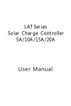
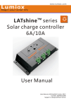
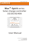
SC MPPT series Solar charge controller SC-10 MPPT: 10A,100VDC max SC-15 MPPT: 15A,100VDC max SC-20 MPPT: 20A,100VDC max User Manual www.opti-solar.com Dear Clients, Solar charge controller Thanks for selecting the SC MPPT series solar controller. Please take the time to read this user manual, this will help you to make full use of many advantages the controller can provide your solar system. This manual gives important recommendations for installing and using and so on. Read it carefully in your own interest please. 3.Dimensions 1.Description of Function SC MPPT series solar controller is based on an advanced maximum power point tracking (MPPT) technology developed, dedicated to the solar system, the controller conversion efficiency up to 98%. 164 It comes with a number of outstanding features, such as: Innovative MPPT technology, conversion efficiency up to 98% Many choices of battery type and working mode Clear readable display of charge/discharge, battery and error description 12V/24V automatic recognition 189 Temperature compensation Perfect EMC design Four stage charge way: MPPT, boost, equalization, float 73 Full automatic electronic protect function 2.Safety instructions and waiver of liability 2.1 Safety ①The solar charge controller may only be used in PV systems in accordance with this user manual and the 4.Installation The following diagrams provide an overview of the connections and the proper order. specifications of other modules manufacturers. No energy source other than a solar generator may be connected to the solar charge controller. ②Batteries store a large amount of energy, never short circuit a battery under all circumstances. We strongly recommend connecting a fuse directly to the battery to protect any short circuit at the battery wiring. ③Batteries can produce flammable gases. Avoid making sparks, using fire or any naked flame. Make sure that the battery room is ventilated. ④Avoid touching or short circuiting wires or terminals. ③ ④ ② ① ⑥ ⑤ Be aware that the voltages on special terminals or wires can be as much as twice the battery voltage. Use To avoid any voltage on the wires, first connect the wire to isolated tools, stand on dry ground, and keep your hands dry. the controller, then to the battery, panel or load. ⑤Keep children away from batteries and the charge Make sure the wire length between battery and controller controller. is as short as possible. Recommended minimum wire size: 2.2 Liability Exclusion The manufacturer shall not be liable for damages, especially on the batter y, caused by use other than as intended or as mentioned in this manual or if the recommendations of the batter y manufacturer are neglected. The manufacturer shall not be liable if there has been ser vice or repair carried out by any unauthorized person, unusual use, wrong 10A : 2.5mm²; 15/20A : 4mm². Be aware that the negative terminals of SC MPPT are connected together and therefore have the same electrical potential. If any grounding is required, always do this on the negative wires. Connecting capacitive load may trigger short circuit protection. installation, or bad system design. Page 1 of 4 pages www.opti-solar.com 4.1 Mounting location requirements 5.Star ting up the controller Do not mount the solar charge controller outdoors or in wet rooms. Do not subject the solar charge controller to direct sunshine or other sources of heat. Protect the solar charge controller from dirt and moisture. Mount upright on the wall on a non-flammable substrate. Maintain a minimum clearance of 10cm below and around the device to ensure unhindered air circulation. Mount the solar charge controller as close as possible to the batteries. 4.2 Fastening the solar charge controller Mark the position of the solar charge controller fastening holes on the wall, drill 4 holes and insert dowels, fasten the solar charge controller to the wall with the cable openings facing downwards. 5.1Self Test As soo n as the controller is supplied with batter y, it star ts a s elf test routine. Then the display changes to normal operation. 5.2System Voltage The co ntroller adjusts itself automatically to 12V or 2 4V system voltage. As soon as the batter y voltage a t the time of star t-up is within 10V to 16V, the c ontroller implies a 12V system, else if the batter y v oltage is within 20V to 30V, the controller implies a 24V system. If th e batter y voltage is not within the normal operating rang(ca.10 to 16V or ca.20 to 30V)at star tup, a s tatus display according to the section 6.2 Charge & Error display. 4.3 Connection We strongly recommend connecting a fuse directly to the battery to protect any short circuit at the battery wiring. Solar PV modules create current whenever light strikes them. The current created varies with the light intensity, but even in the case of low levels of light, full voltage is given by the modules. So, protect the solar modules from incident light during installation. Never touch uninsulated cable ends, use only insulated tools, and make sure that the wire diameter is in accordance with the solar charge controller’s expected currents. Connections must always be made in the 5.3Batter y Type The Ma x-Spirit series controller applies to Liquid and Gel batter y, the factor y default setting is suitable for liquid batter y. Please refer to 7.1.2 change setting. 5.4 Work Mode The work mode of the controller is selectable (Standa rd and D2D), the factor y default setting is standard. Please refer to 7.1.1 change setting. sequence described below. Day/Night threshold 1st step: Connect the battery Connect the battery connection cable with the correct polarity to the middle pair of terminals on the solar charge controller (with the battery symbol). If the Day/Night threshold Sunset Light on Sunrise Standard Light on system is 12V, please make sure that the battery voltage is within 10V~16V, else if the system is 24V, the Light off battery voltage should between 20V~30V. If the polarity is correct, the LED on the controller will begin to show. 2nd step: Connect the solar module Ensure that the solar module is protected from incident light. Ensure that the solar module does not exceed the maximum permissible input current. Connect the solar module connection cable to the correct pole of the left pair of terminals on the solar charge controller (with the solar module symbol). 3rd step: Connect loads Connect the load cable to the correct pole of the right pair of terminals on the solar charge controller (with the lamp symbol). To avoid any voltage on the wires, first connect the wire to the load, then to the controller. 4th step: Final work Fasten all cables with strain relief in the direct vicinity of the solar charge controller (clearance of approx.10cm). Page 2 of 4 pages D2D(Dusk to Dawn) www.opti-solar.com 6.Display Functions 7. Inter face Description The controller is equipped with 6 LEDS. In normal operation, the controller shows charge or discharge status, battery capacity and load status. Reser ved DIP Switch 7.1 DIP Switch 6.1 Batter y Capacity display: Yellow 1 Inter face ON 1 2 7.1.1 DIP switch stall 1 -- Work mode (Standard and D2D) Yellow 2 settings, the default is Standard(As shown in figure). If slide Red the DIP switch to “ON”, the controller works in D2D Green mode. ON Red On, Energy of Battery <25%. Yellow 1 On, Energy of Battery is about 25~50%. 1 2 setting is liquid battery (As shown in figure). If slide the DIP Green On, Energy of Battery is about 75~100%. The percentage corresponds to the available energy switch to "ON", the battery type is selected as GEL. ON until low voltage disconnect in relation to a fully charged ON GEL battery. 1 2 6.2 Charge & Error display(INFO): INFO green flashing, that is charging (fast flash Red 1 2 7.1.2 DIP switch stall 2 -- Battery type selection, the default Yellow 2 On, Energy of Battery is about 50~75%. ON D2D Standard for MPPT charge state, slow flash for non MPPT charge state); otherwise, no charge; Green INFO Red On, is Error Status. For more details, please see table below. Error Loads are not supplied Display Red(INFO and Bat.) LED are lighted Red Red LED is flashing Batter y is not being charged during the day Red Reason Remedy Batter y is low Load will reconnect as soon as battery is recharged Fast flash: over current/short circuit of loads Slow flash: over temperature protection Green Solar array faulty Green LED or wrong polarity is off Batter y voltage Over voltage protection Does not recognize the system voltage too high (>15.5V/31V) Red(INFO) and Green(Bat.) Battery wires or LED are battery fuse lighted damaged, battery has high resistance The batter y External temperature sensor and COM communication interface , please consult the supplier. 8.Safety Features 八、安全特性及故障描述 Solar terminal Battery terminal Load terminal Switch off all loads. Remove short circuit. Auto recovery when the temperature is below set value. Remove faulty connection/ reverse polarity Check if other sources overcharge the battery. If not, controller is damaged. Check batter y wires, fuse and batter y. Charge or discharge voltage is not All LED within the normal he battery to make the voltage within Lighted operating rang the normal range at star t-up 1 2 7.2 Reser ved Inter face Reverse polarity Protected *1 Protected *1 Short circuit Protected Protected *3 Switches off immediately Switches off with delay Over current Reverse Current Protected *2 Protected Over voltage Max.100V *4 Max. 40V Under voltage Over temp. Switches off switches off the load if the temperature reaches the set value. *1 Controller can not protect itself in a 24V system when polarity of battery or solar is reversed. *2 Controller can protect itself, but loads might be damaged. *3 Battery must be protected by fuse, or battery will be permanently damaged. *4 The solar panel voltage should not exceed this limit for a long time as voltage protection is done by a varistor. Warning: The combination of different error conditions may cause damage to the controller. Always remove the error before you continue connecting the controller. Page 3 of 4 pages www.opti-solar.com 9.Technical Data Technical Data SC-10 M P P T System voltage 12V/24V automatic recognition Max solar current or load current 10 A Max MPPT efficiency 98% Max PV input power 12V: 150W ,24V: 300W Float voltage 13.7V/27.4V (25℃) Boost voltage 14.5V/29.0V (25℃) Equal voltage 14.8V/29.6V (25℃) (Liquid) Day/Night threshold 5.0V/10.0V Load disconnect voltage 11.2~11.8V/22.4~23.6V Load reconnect voltage 12.5V/25.0V Batter y type Liquid, Gel Work mode Standard, D2D(Dusk to Dawn) Temperature compensation SC-15 M P P T SC-10 M P P T 15 A 20 A 12V: 225W, 24V: 450W 12V: 300W, 24V: 600W -4.17 mV/K per cell (Boost and Equal charge), -3.33 mV/K per cell (Float charge) Max solar voltage 100 V Max batter y voltage 40 V Dimensions/Weiht 164*189*73mm / 800g Max power consumption 10mA Temp. Range during operation -35℃ ~ +55 ℃ Storage temperature -40℃ ~ +80 ℃ Relative humidity 10%~90% Non-condensation Case protection IP22 164*189*73mm / 900g Page 4 of 4 pages