1
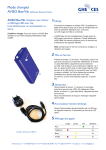
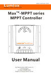
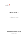
www.lumiax.com
Lumiax
Magic your solar life
TM
LAT -NL Ser ies
So lar Char ge Cont roller
5A /10A /15A /20A
User Manual
1.Description of Function
3.Safety instructions and waiver of liability
LAT-NL series intelligent solar controller is especially
for solar photovoltaic power generation system and
solar street light system.
①The solar charge controller may only be used in PV
3.1 Safety
systems in accordance with this user manual and the
specifications of other modules manufacturers. No
It comes with a number of outstanding features,
energy source other than a solar generator may be
such as:
Programmable nightlight function
12V/24V automatic recognition
Clear readable display of charge/discharge and error
description
Four stages charge way: fast, boost, equal, float
Temperature compensation
Low voltage disconnected reulated by state of charge
Max. 16mm² binding clamp
Full automatic electronic protect function
This manual provides some important
recommendations related to the controller, including
installation, use, programming and fault exclusion.
connected to the solar charge controller.
②Batteries store a large amount of energy, never short
circuit a battery under all circumstances. We strongly
recommend connecting a fuse directly to the battery to
protect any short circuit at the battery wiring.
③Batteries can produce flammable gases. Avoid making
sparks, using fire or any naked flame. Make sure that the
battery room is ventilated.
④Avoid touching or short circuiting wires or terminals.
Be aware that the voltages on special terminals or wires
can be as much as twice the battery voltage. Use
isolated tools, stand on dry ground, and keep your
2.Dimensions
hands dry.
⑤Keep children away from batteries and the charge
controller.
3.2 Liability Exclusion
The manufacturer shall not be liable for damages,
especially on the batter y, caused by use other than
as intended or as mentioned in this manual or if the
recommendations of the batter y manufacturer are
neglected. The manufacturer shall not be liable if
there has been ser vice or repair carried out by any
unauthorized person, unusual use, wrong
installation, or bad system design.
Page 1 of 4 pages
Solar Charge Controller LAT05/10/15/20-NL User Manual
6.Display Functions
4.Installation
The controller is equipped with 5 LEDS.
The following diagrams provide an overview of the
connections and the proper order.
Green*1
Yellow*3
Red*1
In normal operation,the controller shows charge or
discharge status、battery capacity and load status.
6.1Charge display(Green LED):
③
④
①
②
⑤ ⑥
To avoid any voltage on the wires, first connect the wire to
Solar array supplies electricity
(LED is on)
the controller, then to the battery, panel or load.
Solar array does not supply electricity
(LED is off)
6.2Status of charge display(Yellow LED):
Make sure the wire length between battery and controller
is as short as possible.
Recommended minimum wire size: Lat05-NL: 1.5 mm²;
Lat10-NL: 2.5mm²; Lat15/20-NL: 4.0mm².
Be aware that the positive terminal of controller are
connected together and therefore have the same
electrical potential. If any grounding is required, always do
this on the positive wires.
Connecting capacitive load may trigger short circuit
protection.
<25%
25-75%
>75%
The percentage corresponds to the available energy
until low voltage disconnect in relation to a fully
charged batter y.
6.3Load status display(Red LED):
In case of deep discharge or overload/short-circuit
of load, the load output is switched off.
!Remark: If the device is used in a vehicle which has the
battery negative on the chassis, loads connected to the
controller must not have an electric connection to the car
Low voltage
Overload or short-circuit
Normal operation
disconnect(LED is on) of load(LED is flashing)
(LED is off )
body, otherwise the Low Voltage disconnect and electronic
fuse functions of the controller are short circuited.
5.Starting up the controller
7.Low Voltage Disconnect Function
5 . 1Sel f Te s t
As s o on as t h e c on t roll e r is s u pplie d with batter y, it
s t a r ts a s elf test routin e . Then the display change s t o
normal operation .
5.2Syst e m Vo lt a ge
The controller adjusts its e lf automatically to 1 2V or
24V system v ol tage. A s s oon as the batter y vol t a g e at
the time of star t- up is wit h in 10V t o 16V, t h e c on t roll e r
im p lies a 12V system, el s e if the batter y v oltage is
wit h in 2 0V to 30 V,the controller i mpl i e s a 2 4 V s y stem.
If t h e ba t ter y voltage is not withi n the norma l
operating r a n g (ca. 1 0 to 1 6 V or ca.20 t o 30V)at star t- u p,
a status d i splay accordi n g t o the section 1 0 .2 Err o r
description occur.
5.3Batter y Type
The LAT seri e s c on t r o l ler appl i es to L iq u id and Gel
ba t te r y, the factor y d e fault set t ing is s u i table for liqu i d
ba t te r y.
The controller uses state of charge to protect the
batter y form being deeply discharged:
11.2V/22.4V~11.8V/23.6V.
Disconnect at 11.2V/22.4V(at nominal load current)
up to 11.8V/23.6V(at no load current).
!Note:
1. If the controller goes into low voltage protection, it will
restore only when the battery being recharged and the
voltage reaching the reconnect voltage.
2. Around oblique line value separately on behalf of 12V
and 24V system's value.
Page 2 of 4 pages
Solar Charge Controller LAT05/10/15/20-NL User Manual
8.Night light Function
10.Safety
Features and Error description
八、安全特性及故障描述
The charge controller has a load terminal which is
prepared for nightlight operation and switches on
for a selectable number of hours from the dusk .
There are 2 modes available:
Dusk to Dawn and Evening Mode.
10.1 Safety features
Solar terminal Battery terminal Load terminal
Reverse
polarity
Protected *1 Protected *1
Short circuit Protected
Protected *3
Light on
Dusk to Dawn
Light off
Light on
Light off
Reverse
Current
Protected
Number of evening hours
Over voltage Max.55V *4
9.P
rogra mmin
g Functio
n
Programming
Functio
n
9.1Programming Nightlight Function
You enter the programming mode with a long push on
the button. The programming menu structure is described
on the follow.
All programming settings are stored in a non-volatile
memor y and remain stored even if the controller was disconnected from the batter y.
9.2Test Function
During daytime the testing function can help the user to
verify correct installation or for trouble shooting a system
problem. Short pushing the button will light up the lamp
which is connected to the load terminals.
The lights will be on in the day for 1 minute inter vals.
Within 1 minute the lights can be turned off via pushing
button.
State of Charge
Programming Menu
Enter
Programming
L1
L2
L3
Switches off
immediately
Switches off
with delay
Over current
Evening Mode
Protected *2
L4
L5
Evening mode,
8 hours
L5 lighted,
L2 flash
Normal
Operation
Evening mode,
6 hours
L5 lighted,
L3 flash
(Exit Programming)
Button
Over temp.
Evening mode,
4 hours
L5 lighted,
L4 flash
LED is Flashing
Short Push <1 Second
LED is On
Long Push >1 Second
LED is Off
Switches off
switches off the load if the temperature
reaches the set value.
*1 Controller can not protect itself in a 24V system when
polarity of battery or solar is reversed.
*2 Controller can protect itself, but loads might be damaged.
*3 Battery must be protected by fuse, or battery will be
permanently damaged.
*4 The solar panel voltage should not exceed this limit for a
long time as voltage protection is done by a varistor.
!Warning: The combination of different error
conditions may cause damage to the controller.
Always remove the error before you continue
connecting the controller.
10.2 Error description
Error
Dusk to Dawn
L5 lighted,
L2/L3/L4 flash
Max. 40V
Under
voltage
Loads
are
not
supplied
Display
Battery is
not being
charged
during
the day
Remedy
Batter y is low
Load will reconnect
as soon as battery
is recharged
Over current/
short circuit
of loads
Switch off all loads.
Remove short
circuit.
Batter y has
low capacity
Change batter y
Red LED
is on
Red LED
is flashing
Battery is
empty after
a short time
Reason
Red LED
is on
Solar array faulty
Green LED or wrong polarity
is off
Batter y voltage
over
voltage
protection
Does not
recognize
the system
voltage
Page 3 of 4 pages
too high
Remove faulty
connection/
reverse polarity
Check if other
sources overcharge
the battery.
If not, controller
is damaged.
(>15.5V/31V)
Red and
Yellow LED
Battery wires or
(the right
Check batter y
battery fuse
side) are
wires,fuse and
damaged, battery
lighted
batter y.
has high resistance
The batter y
voltage is not
Charge or discharge
All LED within the normal the battery to make
the voltage within
Lighted operating rang
at start-up
the normal range
Solar Charge Controller LAT05/10/15/20-NL User Manual
11.Technical Data
Model
LAT05-NL
System voltage
12V/24V automatic recognition
LAT10-NL
Max. solar current or load current
5A
Fast voltage
14.0V/28.0V(25℃)
Boost voltage
14.5V/29.0V (25℃)
Equalization voltage
14.8V/29.6 V (25℃)(Liquid)
Float voltage
13.7V/27.4 V (25℃)
10A
LAT15-NL
LAT20-NL
15A
20A
Load disconnect voltage
11.2~11.8V/22.4~23.6V
Load reconnect voltage
12.5V/25.0V
Working time during night
Dusk to Dawn mode、4、6、8hours(Programmable)
Battery type
Liquid、Gel
Temperature Compensation
-4.17 mV/K per cell(Boost, Equalization); -3.33 mV/K per cell(Float)
Max. solar voltage
55V
Max. ba ttery voltage
40V
Over voltage protection
15.5V/31.0V
Dimensions/ Weight
81*102*37 / 150g
Wire size
16mm²(AWG#6)
Own consumption
4mA
Ambient temperature
-40 ~ +60 ℃
Degree of protection
IP22
User Manual_LAT-NL series_DK29
CE, Rohs, ISO9001:2008
Subject to change without notice!
Page 4 of 4 pages