1
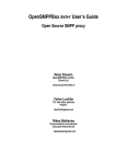
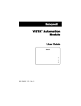
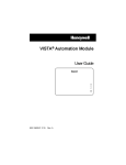
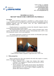
JB-QBC-5i FIRE ALARM CONTROLLER USER’S MANUAL JB-QBC-5i Fire Alarm Controller Hello! Welcome to Brightsky world!The new technical design JB-QBC-5i fire alarm control system will exceed your mind:4 loop look up at the same time,speed fast, function supper;it can connect with XSW-5iwater mist controller as the water mist system, flush mounting fission installation mode is good for the marine, more image interface will let you feel friendly from SCM world,system speed has be improved. Brightsky Electronic aim to high reliability and veracity,which has show. This manual will show you the supper function of the fire alarm controller. Function Image menu operation, new feeling. Alarm message record function. Display each detector state. Support loop wiring mode. 4 Loops,total 1000 pcs intelligent bus-device. Give the bus-device address description to confirm one alarm position.(These description can be input in computer . Then transfer them to fire alarm controller . For more details, Please learn“5i program tool ”manual) All associated message can be programmed in this controller. This controller can reach the China CCS approval requirement for marine fire alarm system. Our Description The following description: Bus-device are smoke detector, heat detector, manual call point, signal input module etc. fire alarm device and remote control module etc associate control device. Due to the habit or description requirement, use “detector ” to replace smoke detector, heat detector, manual call point, signal input module etc fire alarm device. 第 1 页 共 20 页 JB-QBC-5i Fire Alarm Controller Technical data Main power supply(MSBD): Emergency power supply(ESBD) Ship’s DC power supply: Inner battery supply: Power consumption: Basic monitor capacity: rolling period: Signal transmission distance: Wiring mode: Using cable: Output control terminal: Working environment temperature: Relative humidity: Outline dimension: Installation mode: Weight : Alarm record: associate programming max: Detector’s description number: Character of Each detector’s description: AC 220V (+10%~ -15%) ,50HZ AC 220V (+10%~ -15%) ,50HZ DC 24V (+10%~ -10%) DC 24V,7AH Monitor state:≤2.4W;Alarm state:≤10W 4 loops, it can connect 5i series bus-device 1000pcs; The current of one flame detector is the same as 8 normal bus-device’s. ≤10S ≤1500m 1、 Loop wiring 2、 5i series detector — two lines,non-polarity; 3、 5i series module —two lines,polarity(T+—anode, T-—cathode) ; Signal line is 1.5mm2 marine communication cable; Power supply line is 2.5mm2 power cable; Fire alarm output FIRE EXT1~EXT3, fire alarm delay output B1~B3,delay time can be changed. Others like default output etc. 0℃~55℃ ≤95% 290×180×51(H×W×T)mm3 Flush mounting fission installation About 12Kg The number of recording about the alarm message is less than 500pcs(Including opening, fire alarm, fault and associate) 150 ( OR1, OR2, AND logic, each of them 50 ) Less than 1000 Less than 20 English characters or 10 Chinese characters Structure and installation The controller is used flush mounting fission installation,bosom has set up 7AH full airproof no maintenance battery, compact structure, distribution reasonable, outline nice. 第 2 页 共 20 页 JB-QBC-5i Fire Alarm Controller Installation Adopt flush mounting fission installation mode,integrate in operation table of marine wheel house, control display part embed in the control panel,offer the relative connection board,convenience user connection. Installation sketch map is as the following (here connect one set of fire alarm controller and one set of water mist controller): 第 3 页 共 20 页 JB-QBC-5i Fire Alarm Controller Interface board terminal description : 第 4 页 共 20 页 JB-QBC-5i Fire Alarm Controller 第 5 页 共 20 页 JB-QBC-5i Fire Alarm Controller From Installation to Running 1. Please read this manual carefully. 2. According to “Installation” chapter,install the controller. 3. Using mega ohm meter to measure alarm bus, the resistance is more than 20 mega ohm,according to fire control specification requirement to install detectors, meanwhile,it should check the connection diagram whether it’s right or not, each of tighten firmware whether it’s fastened or not. 4. Power on. Basic function Power on First time use this controller, power on all power's switch, after the controller initialize, self-test indicator and sounder, after power supply indicator flash, this system is in normal monitoring state, following is the system normal state’s picture: 10:36 JB-QBC-5i Fire Alarm Control Panel BrightSky Electronic Fire alarm In the normal monitoring state, the controller monitors each of registered detectors,check current smoke deepness or temperature value of each detector, meanwhile, according to this parameter to calculate, identify. If the value reaches the fire alarm’s condition, it will change into the fire alarm state at once. At this time, the controller set out fire alarm sound, fire alarm indicator will flash, the screen display alarm address, quantity, etc information, meanwhile, the output terminal B1/B2/B3 begin to delay,if no man operate the controller within 2 minutes (silence or reset), the delay output will be activated, if the system is in automatic state, the controller will activate remote control module according to the associated program , open or close outside devices (such as fire extinguishing pump etc ). The fire alarm, SuSi(super signal) and associate information is pagination displayed . If there are two alarms at the same time you can use or to switch the alarm type, and use next message in the same type. 第 6 页 共 20 页 or to see the last or the JB-QBC-5i Fire Alarm Controller FirstFile:2001 09:31 Fire:02SuSi:00Asso:00 02/02 2001 09:31 SIGN Engine room in this picture, 02/02,the first “02” means No.2 fire alarm, the second “02” means fire alarm sum is 2 ,2001 is No.1 detector of No.2 loop give this alarm, 09:31 is the fire alarm happening time,SIGN is bus-device type. Engine room is this detector’s description. Fault alarm In order to let fire alarm control system in good condition for a long time, controller should monitor the status of lines, bus-device(detectors, remote control modules etc)and power supply. If the status is abnormal, give fault alarm. During the fault stage the controller set out fault warning sound, the fault indicator in the panel flash,fault type displayed on the screen. If it is the fault of the detector or remote control module, alarm address, quantity, time etc information will be displayed in screen. Operator should debar fault in time, after fault disappear,the controller reset automatically and turn to normal monitoring state. 06/12/17 09:31 Fault Sum:05 02/05 2001 09:31 SIGN Engine room Detector or remote control module fault In normal state, each of detector or remote control module has relatively steady value. If the value is abnormal, it means detectors or remote control modules have some problems, the controller will report detector or remote control module fault. MSBD FAULT--main AC220V power supply fault MSBD fault means the voltage of AC220V power is lower than 187V(including power off),the controller give MSBD fault,fault indicator flash, meanwhile, the controller will switch to the emergency power supply automatically . ESBD FAULT—emergency AC220V power supply fault When it hasn’t ESBD,report ESBD fault. Ship’s DC24V power supply fault When it hasn’t ship’s DC24V input,report DC24V fault. Battery fault Battery fault in the controller means the battery’s voltage is lower than 19.2V, battery break off, or battery cannot be charged, the controller report battery fault. Earth fault When earth insulated resistance of the controller hasn’t reach insulated requirement, it will report earth fault. Loop break off fault 第 7 页 共 20 页 JB-QBC-5i Fire Alarm Controller When the loop has break off, the controller can report the disconnected loop number and T+/T- line disconnected. Door hold fault--Magnetic Door hold disconnection fault In normal, magnetic door hold has EOL. When it is disconnected, report door hold fault. B1/B2 fault--Alarm bell line disconnection In normal, alarm bell has EOL,when control alarm bell break off, report alarm bell break off fault. XSW-5i fault--Water mist controller disconnected or fault When water mist controller combined with fire alarm controller is fault, it will report XSW-5i fault. JB-QBC-5iR fault ---Fire alarm repeater fault When the fire alarm repeater combined with fire alarm controller is fault, it will report JB-QBC-5iR fault. Fire extinguishing zone disconnection fault When the extinguishing zone of water mist controller combined with fire alarm controller is disconnected, it will report fault of fire extinguishing zone. Water pump state monitor Monitor pump status such as pump running, water low level . Device Test Device Test 001 Loop : 01 02 03 04 RegVal: 24 00 00 00 CurVal: 24 00 00 00 Type:SI You can check each module or detector analogue value. 001 means No.1 detector,Loop No. display 4 loops, RegVal is the registered value,CurVal is the analogue value of the module or detector currently;use plus or minus 1 each time . Use or or detector address will detector address will plus or minus 20 each time. Press cancel key to exit Device Test state. Module operation Module operate Module: 0000 ENTER-activated CANCEL- close in monitor state, Press to enter module operation, it can open or closed remote control module directly, press number key to input module address,press enter key to open this module, cancel key closes this module, and return to monitor state. Test Use to test the buzzer, LED, LCD Screen. 第 8 页 共 20 页 JB-QBC-5i Fire Alarm Controller Menu operation function In monitoring state, press function key and enter the password: 进入菜单操作: Menu Password : If the password is correct , you will enter main menu, otherwise return to monitoring state. Main menu had nine menu options (browse, record, time, program, other, register, system , communication , exit). or Press to select each function, press enter key to enter the functions. All the menu need to be operated according to the protocol: press enter key to enter and press cancel key to exit. Browse Browse 02Loop 010 001 002 003 005 006 007 011 012 013 045 02 loop 010 means 10 bus-devices registered in Loop 2, press 1 or loop3,Press or or to switch to Loop to switch to the next page or last page, the loop is the same. Record Record 010/500 FAULT 2002 2006-05-15 09:45 In record there are all informations of fire alarm controller, includ all fire alarm, fault, associate, super signal and water mist fire extinguishing zone action. Max record 500 pieces. Press or to change to the next or last page. Time 第 9 页 共 20 页 JB-QBC-5i Fire Alarm Controller Time 2006/05/15 or Press 09:45 to move cursor, input current machine time, confirm it’s correct, then press enter key . Program Program 001 Logic : AND Condition:1002--1003 Associate:1007--1007 In the item of “logic” , you can choice “OR1”,“OR2”or “AND”.“OR1”means in the “condition” any of alarm can start the bus-device of “associate”, “OR2”means in the “condition” any of two alarms can start bus-device of “associate”,“AND” means in the “condition” all of alarms can start bus-device of “associate”,press or or to change the different logic option,press move cursor to needed location,input the address,after confirm it’s correct, press enter key. The “condition” means all bus-device input,when the analogue value of bus-device in “condition” is rising,according to relative logic relationship to start the remote control module. Press or to edit another one. Other Other 1.LocalBox Setup 2.Type settings 3.Zone mapping 4.Signal Iso Other includes 4 items, No. 1 and No.3 item is designed for water mist controller. Local box setup 第 10 页 共 20 页 JB-QBC-5i Fire Alarm Controller LocalBox Setup Start :1011 Stop :1012 Module:1013 Zone :5001 Start code relative to start button in local control box,stop code relative to stop button in local control box,module code means remote module parts in local control box,zone means water mist control zone of water mist controller,5001 means No.1 fire extinguishing zone of water mist controller, when local control box start button is pressed(need to keep press state several seconds) ,relative fire extinguishing zone start, after press stop button, closed the relative fire extinguishing zone. when fire extinguishing has action,the relative module start in the local control box. Type settings Type settings Range :1001--1001 Type :SMOK When find register bus-device type is wrong, using this option to forced correct the device type of the bus-device. For example: when connected with flame detectors, registered devices type is signal, need to be changed to smoke or complex type, then it can operate. Zone mapping Zone mapping Detec.1:1001--1001 Detec.2:1002--1002 Zone mapping detector 1 and detector 2 relative detector 1 and 2 of water mist control panel, when water mist controller set up automatic mode, and detector 1 and detector 2 alarm at the same time, then start relative fire extinguishing zone. under manual mode, detector 1 and detector 2 can alarm, but it can’t start linkage fire extinguishing zone. Signal isolation 第 11 页 共 20 页 JB-QBC-5i Fire Alarm Controller Signal Iso Signal :2001 Iso Area:2002--2003 Signal isolation is set up for liable to disturb zone,it can isolate effected detectors, prevent fire alarm fault. Signal can be signal input module, remote control module etc. in the example , signal input module 2001 can input, detector 2002 and 2003 can’t report the fire alarm, meanwhile, the indicator of the second loop can flash, it means some detectors in the loop is isolating now. Register Normal register diagram is the following : Register 7-Register Now press“7”key to register,details register diagram is the following: Register 0049/074 0049 means current register detector numbers(4 loops in total) ,074 means current checking detector address, Max address 250 *device register need 2 times, to confirm all register bus-devices be counted. System management There are 15 items in system management, it mainly aim to configure the system states. Associated status System 01/15 Associated Status Auto 第 12 页 共 20 页 JB-QBC-5i Fire Alarm Controller When the linkage state set up automatic, detector report fire alarm, it can be according to programmed logic relationship to start the relative devices,when set up manual, devices only can manual start, the detector only can fire alarm. Main power supply fault monitor System 02/15 MSBD 220VAC Mointor Yes when set up “YES” ,system monitor main power whether it has fault or not. When it has fault, to switch “YES”or“NO”to confirm whether or offers fault alarm. It can press it needs to report fault, press enter to confirm all input informations. Emergency power supply fault monitor System 03/15 ESBD 220VAC Mointor Yes when set up“YES” ,system monitor emergency power whether it has fault or not,when it has or fault,offer fault alarm. It can press to switch “YES” or ”NO” to confirm whether report fault or not,press enter to input the setup, when it hasn’t emergency AC220V power supply,it can set up this item“no need”. DC24V fault monitor System 04/15 Ships DC24V Monitor Yes when set up“YES” ,system monitor whether DC24V power supply has fault or not,when it has fault,it can offer fault alarm. It can press or to switch “YES” or “NO” to confirm whether it needs to report fault or not,press enter to confirm input setup. When the ship hasn’t reserved DC24V power,it can set up this item “NO”. Battery fault monitor 第 13 页 共 20 页 JB-QBC-5i Fire Alarm Controller System 05/15 Battery Mointor Yes when set up “YES” ,system monitor inside battery whether it has fault or not,when it has fault, or it will offer fault alarm. It can press to switch “YES”or“NO”to confirm whether it will report fault or not,Press enter to confirm input setup. Earth fault monitor System 06/15 Earth Fault Mointor Yes The item mostly monitor system whether earth all right or not, when earth can’t be satisfied with requirements, it can offer fault alarm, details operation is the same as last one. Door hold break off fault monitor System 07/15 Door Hold Monitor Yes The item mostly monitor magnetism door whether it has break off or not, when it’s normal, magnetism door output 24V,when it has fire alarm,not output 24V, details operation is the same as last one. Alarm bell break off fault monitor System 08/15 B1/B2(bell) Mointor Yes The item mostly monitor alarm bell whether it has break off or not, when it’s normal, alarm bell hasn’t 24V output ,when fire alarm happened, it hasn’t confirmed in the certain time,output 第 14 页 共 20 页 JB-QBC-5i Fire Alarm Controller 24V,start alarm bell, details operation is the same with last one. Fire alarm repeater break off fault System 09/15 JB-QBC-5iR Mointor Yes The item mostly monitor fire alarm repeater whether it’s right or not, when the communication is not correct, it can offer fault alarm. Details operation is the same as the last one. Water mist controller communicate. System 10/15 XSW-5i Communication Yes The item mostly monitor water mist controller whether it has installed well or not, when the communication isn’t connected, display fault alarm, details operation is the same with the last one. 7 short 1 length happen fountain System 11/15 7-S 1-L Generator Yes 7 short 1 long can control alarm bell to output 7 short 1 length signal, according to practice using, user can chose 7 short 1 length happen fountain,or using outside input 7 short 1 length happen fountain, when set up“inside” ,control signal from GA1 input,when set up “outside” ,7 short 1 long control signal from GA2 input. Send alarm to VDR System 12/15 Send Alarm to VDR Yes 第 15 页 共 20 页 JB-QBC-5i Fire Alarm Controller when designed“YES” ,system will send this machine all faults, fire alarms, linkages, water mist zone states and actions through NMEA0183 format to VDR. You can press or to switch“YES” or “NO”to confirm whether it need to set out signal or not,press enter to confirm input setup. VDR socket connect to A1/B1. Fire alarm repeater sum System 13/15 JB-QBC-5iR Sum 002 According to the users actually requirement, one fire alarm control panel can bring several fire alarm repeaters, in this screen input details count, in order to system monitors all fire alarm repeaters state. Delays System 14/15 B1/B2/B3 Delay(s) 120 Here setup the delay time from fire alarm to alarm bell start, as second as unit. Earth fault grade System 15/15 Earth Fault Grade 052 When details using, it can modify earth fault testing grade in the certain range. Communication Communication 1.Browse Room Info 2.Exchange Room Info 3.Upload Record 第 16 页 共 20 页 JB-QBC-5i Fire Alarm Controller Online communication menu is mainly used with computers,it can download bus-device position description information, it also can send information of black casket to computer, to offer system analysis. Browse room info Browse Room Info 3004 Beside Engine Room The item has consulted room number,check whether setup has made mistake or not. Press or Press switch to last one or next address,Press or 3005,after press or switch loop signal, can increase fast or reduce address. For example current address is ,the address 3006,After Press ,the address is 4006,after press ,the address is 4026. Exchange room info Exchange Room Info Users can use computers to edit each address relative position description, after computer programmed,use our company offered software to load fire alarm controller. During the details exchange information, the LCD screen can display current exchanged information. Adopt 485communication mode,connect the connection socket A1/B1. The load diagram: 第 17 页 共 20 页 JB-QBC-5i Fire Alarm Controller If it’s first time to use the program,it must press Save to save one standard input format,then open the saved files by notebook software. As the following diagram. Behind the relative address, input details address information,attention:input Chinese max 10 letters,1 Chinese is similar with English or number 2 letters. After setup finished, return to RoomSetup program. Press Load, input setup files. Press Setup edit Baudrate 9600,as the following diagram, Press OK confirmation. System Ver: Chose 2006。 It can choose Loop number,total 4 loops, then set up input address range,at last press Program to input programmed address description information, in the controller display current exchanged information, after set up finished, Press Return to return,finished address position description information setup. Restart the power of controller, the system operates normally. 第 18 页 共 20 页 JB-QBC-5i Fire Alarm Controller Upload record Upload Record Range: 001-- 050 The users can upload the print record into the computer, use the COM received software to get the fire alarm controller history record, For example,input the record: range is from 001 to 050,Using COM to get the following data: ………………….. $ Linkage , No. 5303, water mist zone 3 SV ation,2006/05/22 09:15 $ Linkage , No. 1013 , 13,2006/05/22 09:08 $ inspection , No.1012 , 12,2006/05/22 09:08 $ Fault , No.6013, fire display panel 3 connection fault,2006/05/22 09:05 $ Fault, No. 6012, fire display panel 2 connection fault,2006/05/22 09:05 $ Fault , No 6042, 2 loop tote lines break off, 2006/05/22 09:05 $ Affair, No. 5050, start the machine,2006/05/22 09:03 $ Fault , No. 1002 , 2,2006/05/22 09:02 $ Fault , No. 6001, main power supply fault ,2006/05/22 09:02 $ Fault , No. 6006, urgency power supply fault,2006/05/22 09:02 ………………. Tone up function It can isolate each of loop very fast,directly press“one loop ”~“four loop”one of them,relative loop red indicator always bright, it means loop is isolated. Repairing and Maintenance When open machine, the controller hasn’t any feedback: Check main, reserved power whether it’s normal or repaired to restart the machine. After open machine, the LCD screen display random code: wordage or program has bad or hasn’t tightened, instead or insert chip again, then it’s OK. After open machine, the controller light and sounder patrol check normally, but there hasn’t be in a poor light and display: this is due to LCD screen contrast is too small,so we can’t watch display content, adjust main board contrast electricity position is OK. 第 19 页 共 20 页 JB-QBC-5i Fire Alarm Controller Attention item: Fire alarm controller should have well earth ,there has earth signal in the controller, earth requirements should be fit for GBJ116-88《fire automatic alarm system design requirement 》 chapter 4. Fire alarm controller is belong to fire extinguishing devices, normally there has person keep watch, management and maintain, check the function whether it’s normal or not, at that time, checking the function whether it’s OK or not on time. meanwhile, make the memo at any moment, when it happens fault, You should inform professional person or factory to repair. After the main power stop, using inside power supply of controller, if the controller set out battery fault alarm signal, it means reserved battery voltage is too low, at that time it should using fetch up, to prevent reserved power to discharge , then destroyed battery. Our service The operation person of controller should be trained by our company, when the person is tested by our company, then he can operate the controller, due to basic maintain, the trained person can deal with it. If You unfamiliar the abnormity condition, you can call our service engineer, or we will service on current place. You can also visit our website to know our company dynamic state. Specially Wuxi Brightsky Electronic Co., Ltd will obey abidance development strategy, so our company will keep the modification right which we don’t inform you before. All right by Wuxi Brightsky Electronic Co., Ltd 第 20 页 共 20 页