1
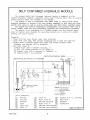
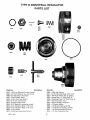
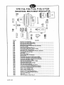
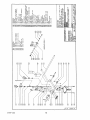
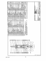
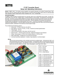
Bettis Canada Ltd.
4112 91A Street
Edmonton, Alberta, Canada T6E 5V2
Tel: (403) 450-3600
Fax: (403) 450-1400
Edmonton
SERVICE MANUAL No. I-0019
SELF CONTAINED
HYDRAULIC ACTUATOR
CUSTOMER:
P.O.#:
W.O.#:
TAG:
DATE:
APPLIES TO OPERATOR MODEL:
DESCRIPTION
DWG.NO
PAGE
INTRODUCTION . . . . . . . . . . . . . . . . . . . . . . . . . . . . . . . . . . . . . . . . . . C-0251 . . . . . . . .
2
I
INSTALLATION AND OPERATION . . . . . . . . . . . . . . . . . . . . . . . . . . . . . . . . . . . . . . . . . . .
3
II
SPECIFICATIONS . . . . . . . . . . . . . . . . . . . . . . . . . . . . . . . . . . . . . . . . . . . . . . . . . . . . . . . .
5
RESET VALVE . . . . . . . . . . . . . . . . . . . . . . . . . . . . . . . . . . . . . . . . . . . C-0069 . . . . . . . .
6
HANDPUMP . . . . . . . . . . . . . . . . . . . . . . . . . . . . . . . . . . . . . . . . . . . . . AB0188 . . . . . . .
7
REGULATOR PARTS LIST . . . . . . . . . . . . . . . . . . . . . . . . . . . . . . . . . . . . . . . . . . . . . . . . .
8
PRESSUREMATIC . . . . . . . . . . . . . . . . . . . . . . . . . . . . . . . . . . . . . . . . . . . . . . . . . . . . . . .
10
PRESSUREMATIC ASSEMBLY . . . . . . . . . . . . . . . . . . . . . . . . . . . . . . APB0570 . . . . . .
11
PRESSUREGUARD ASSEMBLY . . . . . . . . . . . . . . . . . . . . . . . . . . . . . CB0065-10 . . . . .
12
PRESSUREGUARD ASSEMBLY AND DIMENSIONAL . . . . . . . . . . . . . CB0065-00 . . . . .
13
TYPICAL GVO-HP-FS CLOSE COUPLED ASSEMBLY . . . . . . . . . . . . CB0210 . . . . . . .
14
TYPICAL GVO-HP-FS-UM ASSEMBLY . . . . . . . . . . . . . . . . . . . . . . . . AB0444-10 . . . . .
15
TYPICAL QUARTERTURN HYDRAULIC SERIES ASSEMBLY . . . . . . AB0520 . . . . . . .
16
NOTES
17
III
IV
.............................................................
I-0019--.WPD/1
REV4:MAR-21-98
I
INSTALLATION
Refer to schematic drawing C-0251.
The self contained hydraulic esd module is usually factory installed on the operator, but can
be field installed by the user.
The module type may be :
a) low pressure MAWP 200 psi.
b) high pressure MAWP 1500 psi.
It is mounted on the operator with bracket(s) and mounting bolts.
Identified on manifold assembly :
(H)
High pressure hydraulic supply to the operator
(L)
Low pressure hydraulic supply for monitoring/devices
(S)
Low pressure hydraulic signal for RESET VALVE from monitoring/ESD devices
(V)
Vent or return line to allow off panel devices to return oil to the reservoir
Connections are as shown on the schematic, and also tagged at the factory. Solenoid
valve(s), if applicable, have been factory installed and tubed, ready for electrical
connections. The breather/fill port of the reservoir may be plugged with a metal or plastic
plug, if so remove and replace with breather provided in bag attached to the unit.
An aviation grade hydraulic fluid (ESSO UNIVIS or EQUIVALENT) is used in all BETTIS
operator systems, or per customer request.
OPERATION
a) MANUAL MODE (TO START-UP/ RESET)
1. Lift the toggle on the manual pilot valve and latch in the up position. Refer to
drawing C-0069 for "Manual Reset" position.
2. Operate handpump to open/close line and pressurize system.
3. Stop pumping when high pressure gauge reading is approximately 10% above
the minimum value required to hold line valve in position.
4. At this point, hydraulic pressure opposing the operator spring holds the line valve
in position.
NOTE:
To start-up without complete system connections PLUG (L) LOW
PRESSURE to prevent fluid flow off the panel. Follow instructions
above to operate unit.
b) AUTOMATIC MODE (TO RUN)
1. Lower the toggle on the manual pilot valve. Refer to drawing C-0069 for
“Auto/Run" position.
2. Automatic mode is attained when signal device(s) is satisfied. Solenoid valve(s)
is returned to normal operating condition (ie. energized, de-energized).
(i-0019--.wpd)
3
SHUTDOWN
a) Signal devices: If the pilot senses pressure outside of the setpoints; or if there is an
applied/removed electrical signal to solenoid; it removes the signal to the manual
pilot valve. This manual pilot valve switches, which allows the spring in the operator
to stroke the line valve to the failsafe position.
b) Manual shutdown: Push toggle to shutdown manually.
MAINTENANCE
NOTE:
Regular maintenance should be performed each autumn or as required.
1. Drain any accumulated moisture from fluid reservoir.
2. Check, clean and/or replace filter element(s).
3. Check pressure relief valve(s) setpoints and reset values.
4. If possible check operation and calibration of pressure pilot/solenoid.
5. Top up hydraulic fluid with compatible fluid.
TROUBLE SHOOTING
NOTE:
As shown in the schematic, high pressure side of the system supplies the low
pressure regulated side, therefore any leakage on the low side will cause
significant changes in high pressure gauge values in a short time period.
Without cycling the unit, but with the pressurized removal of the reservoir and off panel
device, vent/return lines will assist in tracing leakage. To accomplish this:
1. Remove vent line from pilot/solenoid vent port. This isolates it from the SCH
module and allows for observation of any oil leakage through the device
NOTE:
This checks poppet/spool and spool/sleeve o-ring seal in operating
positions.
2. Remove reservoir from module to observe components (reliefs and reset valve)
for oil leakage while under normal operating pressures.
3. Remove filter plug, spring, and filter in handpump subplate to observe backside of
HP discharge. Check for leakage across and around it with high pressure being
applied.
4. Remove fitting and tubing or plug from module second vent port to observe any
oil leakage due to manifold porosity between LP channel and VENT channel.
5. Remove operator inspection cover/plate and or tubing from cylinder plate port to
observe any oil leakage across piston seal and piston centre o-ring.
In the case of pumping problems, access to pump suction valve is gained by removing
pump assembly from subplate. Pumping difficulties usually result from dirty filter
element, contaminated oil (water, methanol), or incorrect fluid type.
(i-0019--.wpd)
4
Failure of the regulator to regulate is noticeable in that after two pump strokes low
pressure gauge reading is 130 PSI. Service regulator according to enclosed bulletin.
NOTE:
II
Depressurize system before removing/disassembling any components on the
manifold.
SPECIFICATIONS
1. High pressure SCH module with HP-2-SC OR BHP 3 handpump, 0-2000 PSI HP
gauge, and 0-160 PSI LP gauge:
a) HP Relief set at 1500 - 1750 PSI
b) LP Relief set at 130 PSI
c) MECO Regulator set at 80 -100 PSI, recommended setting 80 PSI.
2. Low pressure SCH module with HP-2-SC handpump, and 0-300 PSI LP gauge:
a) LP Relief set at 250 PSI
3. Common components to the low and high pressure systems include:
a) Pilot to close valve, reset valve, toggle valve, or manual pilot valve requires 40 to 60
PSI on the signal port to sustain auto mode.
b) Solenoid valve with voltage of 24 VDC, 125 VDC, or 120 VAC with MAWP 150 PSI to
be specified by user.
c) High/Low pressure pilot upper block connected to the self contained hydraulic
module, with an operating pressure from 60 to 130 PSI. Process sensing pressure
MAWP depends on the manufacturer.
d) For valve operator, see the service manual for particular type.
e) Reservoir is cast aluminum, fabricated steel is optional.
NOTE:
(i-0019--.wpd)
If parts are required, advise model and serial number of equipment.
5
III
PRESSUREMATIC
Set point adjustment for Series 2000, 2200, 2400:
NOTE:
Refer to drawing APB0570.
This is done with the assembly complete and supply air on the pilot valve for P-AR and PMR models.
NOTE:
In the field this requires a calibration kit with the ability to supply high and low
setpoint pressures (eg. nitrogen bottle with block & bleed valve).
1. Cases with low and high set points:
NOTE:
The low set point must be adjusted first. It will not be affected by the high set
point adjustment but the high set point is affected when the low set point is
adjusted.
a) Set the high trip bolt fully away from the trip spring.
b) Repeatedly adjust the low trip bolt and decrease pressure through the low set point
until the low trip occurs consistently at the low set point. Tighten the lock nut and
recheck. Check that there is at least 0.02" piston travel from low trip to bottom stop.
NOTE:
When adjusting the low trip bolt, the upper arm of the trip spring must be
pushed down. This unloads the bolt and allows it to be turned by hand.
c) Repeatedly adjust the high trip bolt and increase pressure through the high set point
until the high trip occurs consistently at the high set point. Tighten the lock nut and
recheck.
2. Cases with low set point only:
a) Set high trip bolt fully away from the trip spring.
b) Adjust the low set point as described in 1.b) above.
c) To disable high trip, increase pressure until piston is at upper stop. Adjust high trip
bolt downward until high trip occurs then retract 1/2 turn. Check that high trip does
not occur when piston travels to upper stop. This high trip bolt adjustment is to
prevent the trip spring from placing unnecessary force on the spool.
3. Cases with high set point only:
a) To disable low trip, adjust low trip bolt until low trip occurs when piston is within
0.020” of bottom stop. Then adjust 3 turns upward (ccw viewed from above).
Tighten locknut and check that low trip does not occur when piston travels to bottom
stop.
b) Adjust the high set point as described in 1.c) above.
(i-0019--.wpd)
10
IV
SELF CONTAINED HYDRAULIC MODULE NOTES
(i-0019--.wpd/17 rev4:rp/ps-1998-03-15 app
dist:(EF)O);(SM)P)