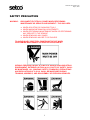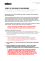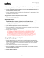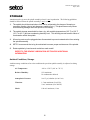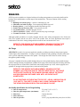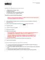
1
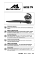
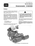
SERVICE MANUAL
Instructions for the
Use and Care of Precision
SETCO Spindles
Publication:
Date of Issue:
Issued By:
R-0007-5
May 27, 2008
SETCO Sales Company
5880 Hillside Avenue
Cincinnati, Ohio 45233
513-941-5110
Publication No. R-0007-5-final
May 27, 2008
PREFACE
SETCO spindles are super precision components that require the highest level of care and handling. All
SETCO precision spindles are manufactured to the highest quality having passed inspection, testing and
run-off procedures prior to shipment. Compliance with the recommended care and handling procedures
will ensure long spindle life, reliability and the highest quality of performance when placed into service.
The purpose of this precision spindle care and handling manual is to assist in the proper handling,
installation, operation and maintenance of the precision spindle assembly. Some precision spindles are
complex systems, which require auxiliary support equipment for complete operation of the spindle. A
thorough background of the precision spindle assembly functionality and the operating parameters of its
auxiliary support equipment is strongly recommended prior to putting the spindle into service. Therefore,
SETCO recommends that the precision spindle assembly be maintained and operated by well-trained and
qualified personnel.
FAILURE TO COMPLY WITH THE PROCEDURES AND SPECIFICATIONS
CONTAINED IN THIS DOCUMENT MAY RESULT IN SPINDLE FAILURE,
PERSONAL INJURY AND/OR VOIDING OF THE SPINDLE WARRANTY
KEEP ALL UNAUTHORIZED PERSONNEL AWAY FROM SPINDLE ASSEMBLY
AND/OR ITS COMPONENTS.
DISCLAIMER
The products described in this publication may employ or create hazardous conditions that could through
misuse, inattention, or lack of understanding, result in damage to the product or to the equipment, or result
in personal injury. It is imperative, therefore, that personnel involved in the handling, installation,
maintenance, or use of this product read, understand and comply to the operation of the product and the
contents of this publication.
This document is based on information available at the time of its publication. While efforts have been
made to be accurate, the information contained herein does not intend to cover all details or variations of the
products, nor to provide for every possible contingency in connection with handling, installation, operation,
or maintenance. Features may be described herein, which are not present in or on all products. SETCO
assumes no obligation of notice to holders of this document with respect to changes subsequently made.
SETCO makes no representation or warranty, expressed, implied, or statutory with respect to, and assumes
no responsibility for the accuracy, completeness, sufficiency, or usefulness of the information contained
herein. No warranties of merchantability or fitness for purposes shall apply.
No part of this document may be reproduced or transmitted in any form or by means, electronic or
mechanical, for any purpose, without the express written permission of the SETCO Corporate Office.
Do to continual improvement, specifications are subject to change without notice. For most current
specifications, visit our website: setcousa.com
© 2007 SETCO Sales Company
SETCO™, AIRSHIELD™, and GOLD LINE™ are trademarks of the SETCO Sales Company.
i
Publication No. R-0007-5-final
May 27, 2008
Table of Contents
SAFTEY PRECAUTION.......................................................................................................... 1 GENERAL SAFEGUARDS ..................................................................................................... 2 UNCRATING THE SPINDLE .................................................................................................. 4 LIFTING AND TRANSPORTING ............................................................................................ 5 Block Style Spindle Housings ............................................................................................ 6 Cartridge & Flanged Cartridge Spindle Housings .............................................................. 7 Transporting Spindles........................................................................................................ 7 MOUNTING THE SPINDLE .................................................................................................... 8 Mounting Accessories ....................................................................................................... 9 START UP AND RUN IN PROCEDURES ............................................................................ 10 Initial Start up and Break-in Procedure............................................................................ 10 Start Up Procedure for an Idle Spindle 1-Week or More ................................................. 11 Daily Run-In Procedure ................................................................................................... 11 Abbreviated Run-in Procedure for a Spindle with 1/2 - 2 hours of Idle Time ................... 11 STORAGE ............................................................................................................................. 12 Ambient Conditions, Storage ........................................................................................... 12 LUBRICATION ...................................................................................................................... 13 Grease Lubrication .......................................................................................................... 13 Air/Oil Lubrication ............................................................................................................ 13 Air Quality Specification for Air/Oil Lubrication ................................................................... 14 Setup Recommendations ......................................................................................................... 14 Procedure to connect the air/oil lubrication system ................................................................. 15 Oil Lubrication.................................................................................................................. 16 SEALING .............................................................................................................................. 17 Air Purge.......................................................................................................................... 17 Air Quality Specification for Air Purge Sealing...................................................................... 17 Procedure to Connect the Air Purge System ........................................................................... 18 Bearing Isolators.............................................................................................................. 19 Recommendations for Spindles Arranged with Bearing Isolators........................................... 19 Positive Internal Pressure (PIP) System ......................................................................... 20 Air Quality Requirements........................................................................................................ 20 Procedure to Connect a Positive Internal Air Purge (PIP) System .......................................... 21 SETCO AirShieldTM (SAS and USAS) ............................................................................. 22 Procedure to Connect the SETCO AirShield (SAS and USAS*) System ............................... 24 VIBRATION MEASUREMENT.............................................................................................. 25 Instrumentation and Equipment ....................................................................................... 25 Testing Procedure .................................................................................................................... 26 Vibration Transducers ..................................................................................................... 26 Magnet Mounted Transducer .......................................................................................... 26 Stud Mounted Transducer ............................................................................................... 26 Data Collection ................................................................................................................ 27 Baseline Signature ................................................................................................................... 28 ELECTRICAL CONNECTIONS ............................................................................................ 29 Supply Disconnecting Device .......................................................................................... 29 HYDRAULIC AND PNEUMATIC ACCESSORIES ............................................................... 30 ii
Publication No. R-0007-5-final
May 27, 2008
COOLING ............................................................................................................................ 31 Coolant Requirements – General Conditions ................................................................ 31 Setup Recommendations .............................................................................................. 32 Bearing Cooling ............................................................................................................. 32 Clustered Spindle Cooling ............................................................................................. 34 TRANSPORTING AND OPERATING CONDITIONS ......................................................... 35 Ambient Conditions, Transporting ................................................................................. 35 Ambient Conditions, Operation ...................................................................................... 35 PERIODIC MAINTENANCE................................................................................................ 36 Coolant Management .................................................................................................... 36 Belt Tensioning .............................................................................................................. 37 Lubrication ..................................................................................................................... 38 Drawbar Maintenance ................................................................................................... 38 Dry Floor and Tunnel Guarding ..................................................................................... 38 General Considerations ................................................................................................. 39 TROUBLESHOOTING ........................................................................................................ 40 PRODUCT SUPPORT ........................................................................................................ 41 SETCO Service Locations ............................................................................................. 41 Notes
iii
Publication No. R-0007-5-final
May 27, 2008
SAFTEY PRECAUTION
WARNING:
DISCONNECT ELECTRICAL POWER WHEN PERFORMING
MAINTENANCE OR SERVICE ON EQUIPMENT! THIS INCLUDES:
♦ WHEN ADJUSTING OR CHANGING TOOLS
♦ WHEN MAKING MECHANICAL ADJUSTMENTS
♦ WHEN PERFORMING MAINTENANCE WORK OR PERFORMING
ANY SERVICE TO THE SPINDLE
♦ WHEN REMOVING ANY GUARD
♦ WHEN REMOVING ANY BELTS OR PULLEYS
TO AVOID INJURY, ELECTRICL POWER MUST BE OFF WHEN
PERFORMING MAINTENANCE OR SERVICE ON EQUIPMENT!
SERIOUS PERSONAL INJURY IS ALWAYS A HAZARD IN AN INDUSTRIAL
ENVIRONMENT. EXTREME CAUTION, IN ALL FACETS OF SAFETY, SHALL
BE MAINTAINED. ALL COMPANY SAFETY STANDARDS, PRECAUTIONS
AND REGULATIONS OF O.S.H.A. SHALL BE MAINTAINED DURING
TRAINING, ASSEMBLY, AND DISASSEMBLY OF PRECISION SPINDLES.
1
Publication No. R-0007-5-final
May 27, 2008
GENERAL SAFEGUARDS
DO NOT OPERATE THE SPINDLE ASSEMBLY AND/OR ITS COMPONENTS
UNLESS YOU HAVE READ THIS DOCUMENT. RETAIN FOR FUTURE
REFERENCE. FOLLOW ALL WARNINGS AND INSTRUCTIONS MARKED ON
THE SPINDLE ASSEMBLY AND/OR ITS COMPONENTS.
1.
Read Instructions
Read all the safety and operating instructions prior to operating a precision spindle assembly
and/or its components.
2.
Retain Instructions
The safety and operating instructions of the precision spindle assembly and/or its components
should be adhered to. These documents should be retained for future reference.
3.
Heed Warnings
All warnings on the precision spindle assembly, its components, and operating instructions should
be adhered to.
4.
Follow Instructions
All operating and user instructions of the precision spindle assembly and/or its components should
be followed.
5.
Attachments and Equipment
Never add any attachments and/or equipment to the precision spindle assembly without approval
of the manufacturer as such additions may result in spindle failure, personal injury and/or voiding
of the warranty.
6.
Servicing
Do not attempt to service the precision spindle assembly and/or its components yourself as
opening or removing covers and/or guards may expose you to dangerous hazards. Refer all
servicing to qualified service personnel.
7.
Power
Disconnect all power to the precision spindle assembly and/or its components before any
maintenance.
8.
Interlocks
Do not by-pass any protective interlocks built into the spindle assembly and/or its components.
Disabling of interlocks may result in spindle failure, personal injury and/or voiding of the
warranty.
2
Publication No. R-0007-5-final
May 27, 2008
9.
Protection
Always wear proper eye, foot and head protection when lifting, transporting and/or operating any
machinery.
10. Water and Moisture
Unless approved by the manufacturer, do not use the precision spindle assembly and/or its
components where they become immersed in water. The spindle assembly and/or its components
are designed to function in moderate coolant applications.
11. Accessories
Any mounting of the spindle assembly and/or its components should follow the manufacturer’s
instructions, and should use a mounting accessory recommended by the manufacturer, if
applicable.
12. Handling the Spindle
Do not place the spindle assembly and/or its components on an unstable cart, stand, tripod, bracket
or table. The spindle assembly and/or its components may fall, causing serious personal injury
and serious damage to the spindle assembly and/or its components.
A SPINDLE ASSEMBLY AND CART COMBINATION SHOULD BE USED WITH
CARE. QUICK STOPS, EXCESSIVE FORCE, AND UNEVEN SURFACES MAY
CAUSE THE SPINDLE ASSEMBLY AND CART COMBINATION TO
OVERTURN.
13. Overloading
Do not overload the precision spindle assembly and/or its components. The spindle assembly
and/or its components should be operated within their rated capacity.
14. Damage Requiring Service
Disconnect all power to the precision spindle assembly and/or its components and refer servicing
to qualified service personnel under the following conditions:
a. If the spindle assembly and/or its components do not operate normally by following the
operating instructions.
b. If the spindle assembly and/or its components have been dropped or the shipping crate has
been damaged.
c. When the spindle assembly and/or its components exhibit a distinct change in performance.
d. If the spindle assembly and/or its components have been wrecked.
e. If the spindle assembly exhibits a rapid change in operating temperature.
f.
If the spindle assembly exhibits a rapid change in vibration level.
g. If the spindle assembly locks-up and cannot rotate.
3
Publication No. R-0007-5-final
May 27, 2008
UNCRATING THE SPINDLE
SETCO ships each precision spindle assembly in a highly stable shipping container to prevent damage to
the spindle assembly during shipment. The spindle assembly and its components are rigidly fixed to the
container using fasteners and/or metal straps.
Prior to uncrating do the following:
1.
Inspect the shipping container for damage.
2.
Report any damage to the trucking company and to
SETCO’s Service Team.
3.
Document any damage with photographs.
As you uncrate your spindle assembly, please
check to be sure that along with the spindle
assembly and its components, the following items are
included:
1.
A SETCO Service Manual, this document, provides
instructions for the Use and Care of Precision
Spindles. See Fig 1.
2.
A SETCO Gold Line TCT Certificate verifying
tested performance (see fig. 2).
3.
Fig. 1 - Use & Care Manual
A print of the precision spindle outline/assembly
drawing.
Uncrating the spindle
1.
Remove the fasteners and/or metal straps that
secure the spindle assembly to the container during
shipment.
2.
Retain the lifting devices for lifting and transporting.
Fig. 2 - SETCO Goldline Certificate
4
Publication No. R-0007-5-final
May 27, 2008
LIFTING AND TRANSPORTING
IMPROPER LIFTING OF A SPINDLE ASSEMBLY CAN RESULT IN DAMAGE
TO THE EQUIPMENT AND BODILY HARM TO PERSONNEL.
Prior to removing the spindle assembly from the shipping container perform the following:
1.
Visually inspect the spindle assembly for any damage that may have occurred during
shipment. If damage to the spindle is evident, immediately notify the trucking company and
SETCO’s service team.
2.
Locate the weight of the spindle assembly, which may be found on the outline drawing, the
shipping container, and/or the spindle nameplate.
3.
Ensure the rated lifting capacity of the hoisting equipment (crane, straps, chains, etc.) is
greater than the weight of the spindle and is in good condition.
4.
Refer to the spindle outline/assembly drawing for the proper method of lifting the spindle
assembly and for the locations and size of the lifting holes.
5.
Make sure the spindle assemblies eyebolts, swivel type hoist rings, or lifting bars are
fastened securely and match the outline/assembly drawing. (Note: not applicable to
cartridge spindles, and flange type cartridge spindles).
6.
Pad all sharp edges of the spindle assembly that might come into contact with the lifting
straps to ensure that lifting straps are not damaged.
NEVER LIFT OR TRANSPORT SPINDLE ASSEMBLY BY ANY OF ITS
ROTATING COMPONENTS.
DO NOT CARRY LOADS OVERHEAD UNLESS ABSOLUTELY NECESSARY.
5
Publication No. R-0007-5-final
May 27, 2008
Block Style Spindle Housings
BLOCK STYLE SPINDLE HOUSINGS are designed to be lifted and transported using either eyebolts
or swivel type hoist rings (see fig. 3). Spindles that are manufactured to be lifted from the top are arranged
with tapped holes in the top of the spindle housing for accepting eyebolts; those that are to be lifted from
the side have tapped holes for mounting swivel type hoist rings. Securely fasten the eyebolts (or swivel
type hoist rings) to the spindle. Lift and transport the spindle using either a lifting strap or chains (see
fig.4) connected to a crane with adequate lifting capacity.
Fig. 3 - View of Eyebolt and Swivel Type Hoist Rings
Fig. 4 - Use of a Lifting Strap or Lifting Chains
6
Publication No. R-0007-5-final
May 27, 2008
Cartridge & Flanged Cartridge Spindle Housings
CARTRIDGE AND FLANGED CARTRIDGE SPINDLE HOUSINGS do
not have provisions for lifting and transporting using eyebolts or swivel type
hoist rings. The proper method for lifting and transporting these types of
spindle housing styles is by use of a lifting strap and crane. Wrap the lifting
strap around the spindle housing ensuring that the strap does not slip. Ensure
that the spindle is securely supported and balanced. Use a crane with adequate
lifting capacity to lift and transport the spindle (see fig. 5).
SPINDLE ASSEMBLIES WITH MOTOR DRIVE PACKAGES employ the
same procedures for lifting and transporting as described for the block style
spindle housings. In addition, use a lifting sling, or if provided the lifting
eyebolt secured to the motor frame, to provide additional support and balance
(see fig. 6).
Fig. 5 – Lifting
Sling on a
Cartridge Spindle.
DO NOT LIFT THE SPINDLE ASSEMBLY USING ONLY THE
MOTOR FRAME EYEBOLT. THE LIFTING ARRANGEMENT
MUST PROVIDE A BALANCED LOAD AND STABLE
CONDITION.
Transporting Spindles
Transporting of the precision spindle assembly for service, or to another
facility, requires that attention be paid to the packaging and crating.
Guidelines for Transporting a Spindle
1.
When a precision spindle assembly is transported, it must be
bolted or banded to the container in which it is to be shipped so
that damage does not occur.
Fig. 6 – Lifting
Arrangement for
Spindle and Motor
Drive Assembly.
2.
The spindle assembly must be completely enclosed within the
container.
3.
The container must properly support the weight of the spindle assembly.
4.
All service ports must be plugged when disconnected to prevent contamination from entering
the spindle assembly.
5.
SETCO recommends shipping of the spindle in its original shipping container.
6.
To prevent excessive shear loading on the eyebolt threads, apply lifting load in-line with the
eyebolt threads. In other words, the chains or lifting straps should be kept in-line with
eyebolt threads and perpendicular to the floor as much as possible.
7
Publication No. R-0007-5-final
May 27, 2008
MOUNTING THE SPINDLE
Installation of the precision spindle assembly onto the machine must be handled with extreme care. The
spindle assembly must not be bumped or dropped to avoid damage.
The precision spindle assembly is to be carefully mounted onto the machine using chains or lifting straps
and hoisting equipment having adequate lifting capacity.
NEVER FORCE A SPINDLE INTO POSITION. A RUNNING OR SLIDING FIT IS
RECOMMENDED.
NEVER FORCE A CARTRIDGE SPINDLE INTO A HOUSING.
WHEN USING POWER LIFTING DEVICES, CARE SHOULD BE TAKEN NOT
TO BIND THE SPINDLE.
For optimum spindle performance, the mounting surface to which the spindle assembly is to mount must
be to the highest quality; including:
♦
♦
♦
♦
♦
Cleanliness
Strength
Flatness
Surface finish
Vibration damping
Secure the precision spindle assembly to the mounting surface using the appropriate mounting hole
locations, bolt sizes (bolts are not supplied by SETCO) and standard torque values.
REFER TO THE SPINDLE OUTLINE/ASSEMBLY DRAWING FOR THE
MOUNTING HOLE LOCATIONS, SIZE, AND APPLICATION SPECIFICATIONS.
DO NOT OVER-TIGHTEN THE MOUNTING BOLTS. OVER-TIGHTENING OF
THE MOUNTING BOLTS WILL DISTORT THE SPINDLE HOUSING
RESULTING IN IMMEDIATE SPINDLE FAILURE AND VOIDING OF THE
SPINDLE WARRANTY.
After mounting is complete, any pneumatic, hydraulic, coolant, or electrical connections to the spindle
should be completed, if required. Refer to the spindle outline/assembly drawing for the required spindle
services and the related specifications.
8
Publication No. R-0007-5-final
May 27, 2008
Mounting Accessories
ROTATING COOLANT UNIONS are typically mounted on the rear of the precision spindle assembly
to provide coolant through the spindle shaft.
Use the following procedures for installation of the rotating coolant union as a guide. Superseded by
rotating coolant union manufacturer’s installation instructions. Refer to manufacturer’s literature for
proper installation instructions.
♦ Improper use may result in premature leakage or failure of the coolant union.
♦ Periodically inspect the coolant union for wear and tear, as the seal wears out, the coolant union
must be replaced or repaired to avoid the consequence of leakage.
♦ Keep vent holes clear and non-restricted.
♦ Should a drain line be required to redirect leakage, contact the SETCO Service Team or the
manufacturer of the coolant union.
♦ Secure the rotating coolant union to the spindle shaft by:
o Connect both supply and drain hoses to the union before mounting the union on the
spindle.
o Thoroughly clean all mounting surfaces before installing the union.
o Verify all drain holes run downward continuously.
o Insert the male threads of the coolant union into the rear of the spindle shaft.
o Using the proper tools on the rotor hex, tighten the rotor threads until the male pilot on
the rotor seats on the diameter and the face of the spindle shaft. Verify thread form using
outline drawing as reference.
♦ No exterior bracing should be used to prevent the housing of the rotating coolant union from
rotating.
♦ Use only flexible connections. DO NOT PIPE SOLID.
♦ Do not install hose taut.
♦ Avoid operation of coolant union at maximum rated pressure with maximum rated speed. If
operating conditions are marginal, consult the SETCO Service Team or the coolant manufacturer.
♦ Rotating coolant unions that are equipped with grease fittings or oil cups require periodic
lubrication. Contact the coolant union manufacturer for a lubrication guide.
♦ Do not run dry.
9
Publication No. R-0007-5-final
May 27, 2008
START UP AND RUN IN PROCEDURES
Although each spindle is ran-off at SETCO prior to shipment, it must further be ran-off by the customer
prior to being placing in operation. This will ensure proper channeling of the bearing lubrication to
prevent excessive bearing temperatures which could result in immediate bearing failure.
Prior to spindle start-up and run-in, a check of any auxiliary systems for proper flows, pressures, and
temperatures must occur. All of the information, when required, is defined by SETCO outline drawing
and described in this section.
The run-in procedures are broken down into four sections. The first section should be followed when the
spindle is being operated for the first time. The second section should be followed when the spindle is
being operated after it has sat idle for a week or more. The third section should be followed when the
spindle is being operated after it has sat idle for 24 hours. The fourth section should be followed when the
spindle is being operated after it is has sat for a short period of time (1/2 - 2 hours).
The following guidelines must be adhered to in order to ensure proper channeling of the bearing
grease lubrication. Improper spindle start-up could result in spindle failure.
FEDERAL LAW PROHIBITS SHIPMENT OF AN OIL LUBRICATED SPINDLE
WITH OIL IN THE RESERVOIR. THEREFORE, ALL SPINDLES MUST BE
PROPERLY FILLED BY THE SPINDLE USER PRIOR TO INSTALLATION.
Initial Start up and Break-in Procedure
1.
Start the heat exchanger, when required, and run coolant throughout the motor coolant
passages (and bearing passages, if required) until the temperature stabilizes. See pages 2,
3, 30, 31, 32, 33, and SETCO’s outline drawing for bearing and motor cooling operating
cautions and parameters.
2.
Verify that all required auxiliary systems are operating properly.
AIR/OIL LUBRICATION MUST BE STARTED A MINIMUM OF 15 MINUTES
PRIOR TO STARTING THE SPINDLE ASSEMBLY AND MUST REMAIN ON
FOR A MINIMUM OF 5 MINUTES AFTER THE SPINDLE HAS STOPPED AND
THE COOLANT HAS STOPPED FLOWING.
3.
Run the spindle at 25% of the rated speed (as shown on the nameplate) for approximately
1/2 hour.
4.
Monitor the temperature of the front and rear bearings. This can be done by taking
temperature readings with a pyrometer at various locations around the front and
rear housing. If the temperature does not reach 140 degrees Fahrenheit move to the next
step.
IF THE BEARING TEMPERATURE REACHES 140 DEGREES FAHRENHEIT,
OR HIGHER AT ANY TIME DURING THE RUN-IN PROCEDURE, OR THE
TEMPERATURE INCREASES MORE THAN 5 DEGREES FAHRENHEIT IN (1)
MINUTE, IMMEDIATELY SHUT THE SPINDLE OFF AND ALLOW IT TO COOL
TO ROOM TEMPERATURE. ONCE AT ROOM TEMPERATRE, RE-START THE
RUN-IN PROCEDURE AT THE STEP AT WHICH IT WAS SHUT DOWN.
10
Publication No. R-0007-5-final
May 27, 2008
5.
Increase the operating speed of the spindle to 50% of the rated speed for approximately 1/2
hour and repeat the temperature check.
6.
Increase the operating speed of the spindle to 75% of the rated speed for approximately 1/2
hour and repeat the temperature check.
7.
Increase the operating speed of the spindle to the full rated speed for approximately 1/2 hour
and repeat the temperature check.
Start Up Procedure for an Idle Spindle 1-Week or More
1.
Follow the initial start-up procedure.
Daily Run-In Procedure
1.
Start the heat exchanger, when required, and run coolant throughout the motor coolant
passages (and bearing passages, if required) until the temperature stabilizes.
See pages 2, 3, 30, 31, 32, 33 and SETCO’s outline drawing for bearing and motor cooling
operating cautions and parameters.
2.
Verify that all required auxiliary systems are operating properly.
3.
Run the spindle at 50% of the rated speed (as shown on the nameplate) for ten (10) minutes
and check the front and rear bearing temperatures.
4.
Start the machine for operation.
IF THE BEARING TEMPERATURE REACHES 140 DEGREES FAHRENHEIT,
OR HIGHER AT ANY TIME DURING THE RUN-IN PROCEDURE, OR THE
TEMPERATURE INCREASES MORE THAN 5 DEGREES FAHRENHEIT IN (1)
MINUTE, IMMEDIATELY SHUT THE SPINDLE OFF AND ALLOW IT TO COOL
TO ROOM TEMPERATURE. ONCE AT ROOM TEMPERATRE, RE-START THE
RUN-IN PROCEDURE AT THE STEP AT WHICH IT WAS SHUT DOWN.
Abbreviated Run-in Procedure for a Spindle
with 1/2 - 2 hours of Idle Time
1.
Start the heat exchanger, when required, and run coolant throughout the motor coolant
passages (and bearing passages, if required) until the temperature stabilizes. See pages 2,
3, 30, 31, 32, 33, and SETCO’s outline drawing for bearing and motor cooling operating
cautions and parameters.
2.
Verify that all required auxiliary systems are operating properly.
3.
Run the spindle at 50% of the rated speed for approximately 3-5 minutes and monitor the
front and rear bearing temperatures.
4.
Start the machine for operation.
11
Publication No. R-0007-5-final
May 27, 2008
STORAGE
Attention must be given to the spindle assembly when it is not in production. The following guidelines
should be followed when the spindle assembly is not in service:
1.
The spindle should be stored where it will not be subjected to the danger of bumping or
excessive vibration (due to jack hammers, machines, etc.) This phenomenon may cause
severe bearing damage when the spindle is not rotating.
2.
The spindle storage area should be clean, dry, with a stable temperature of 65° F to 120° F
(18° C to 49° C) and non-condensing humidity level. This will help prevent harmful effects of
condensation within the spindle.
3.
All service ports must be plugged when disconnected to prevent contamination from entering
the spindle assembly.
4.
SETCO recommends that a log be maintained to ensure proper maintenance of the spindle.
5.
Rotate spindles by hand several revolutions each month!
REFER TO THE SPINDLE LUBRICATION SECTION FOR ADDITIONAL
INFORMATION.
Ambient Conditions, Storage
Ambient storage conditions refer to the conditions the precision spindle assembly is subjected to during
storage.
Air Temperature:
-40° to +158° F (-40° to +70° C)
Relative Humidity:
95% maximum
No condensation allowed
Atmospheric Pressure:
9 to 15 psi, absolute (0.6 to 1 bar)
Vibration:
1.5 mm maximum (2 to 9 Hz),
5 m/s² maximum (9 to 200 Hz)
Shock:
100 m/s² maximum, 11 ms
12
Publication No. R-0007-5-final
May 27, 2008
LUBRICATION
Because of the various applications encountered by a precision spindle assembly, several methods of
lubrication are employed. To ensure the successful operation of a precision spindle
assembly the importance of the correct type and method of lubrication cannot be over emphasized.
Grease Lubrication
GREASE LUBRICATION is widely used in a precision spindle assembly since it provides the simplest
and most economical method of lubricating bearings while providing some degree of protection against the
ingress of coolant and contaminants. Grease lubrication provides:
♦
♦
♦
♦
Maintenance-free operation
Does not require re-lubrication
Spindles are permanently grease lubricated
Lubricated for life.
Air/Oil Lubrication
AIR/OIL LUBRICATION is an extremely efficient and reliable method for lubricating bearings in a
precision spindle assembly while providing some degree of protection against the ingress of coolant and
contaminants. It provides a medium-pressure air sealing arrangement to the spindle assembly. The oil
lubrication to the spindle bearings is carried by air pressure at approximately 30 psi (2.1 bar).
Air/oil lubrication is introduced into the spindle through inlet ports machined into the spindle housing.
Typically, there is one port for each bearing in the spindle assembly.
REFER TO THE SPINDLE OUTLINE/ASSEMBLY DRAWING AND/OR THE
SPINDLE NAMEPLATE FOR THE EXACT AIR AND OIL LUBRICATION
SPECIFICATIONS USED IN THE PRECISION SPINDLE ASSEMBLY.
REFER TO THE SPINDLE OUTLINE/ASSEMBLY DRAWING FOR THE
NUMBER, LOCATION AND SIZE OF THE AIR/OIL LUBRICATION INLET
PORTS.
DO NOT MISTAKE AIR/OIL LUBRICATION INLETS FOR AIR PURGE, ‘PIP’ OR
‘SAS’ (SETCO AIRSHIELD) INLETS. FAILURE TO COMPLY MAY CAUSE
CONTAMINATION AND/OR LACK OF PROPER LIBRICATION OF THE
SPINDLE BEARINGS RESULTING IN SPINDLE FAILURE.
13
Publication No. R-0007-5-final
May 27, 2008
Air Quality Specification for Air/Oil Lubrication
♦
♦
♦
♦
Inlet air temperature:
Inlet dew point temperature (max):
Filter Size:
Filter efficiency:
70° to 90° F (21° to 32° C)
45° F (7° C)
5.0 micron, maximum
99.99%
The recommended air/oil lubrication system consists of:
♦ A quality air/oil lubrication package that includes:
⇒ Pump-manifold-reservoir combination to include outlet check valve, system fill check
valve, high-pressure blowout assembly and pressure gauge.
⇒ Controller
⇒ Pneumatic solenoid valve
⇒ Low-level switch
⇒ Panel (optional).
♦ Pre-oil filter
♦ Final oil filter
♦ Divider valve
♦ Cycle switch
♦ Air flow switch
♦ Low-pressure check valve (one per bearing lubrication point).
♦ Air-oil mixing block (one per bearing lubrication point).
♦ Nozzle adapter assembly (one per bearing lubrication point).
♦ Relief valve
GENERALLY, NOZZLE TUBES ARE NOT REQUIRED IN THAT THE OIL
RESTRICTION TO THE BEARING IS MACHINED INTO THE BEARING
SPACERS.
Setup Recommendations
♦ Spindle drain holes must be oriented toward the ground.
♦ Properly seal all hydraulic, pneumatic and electrical connections. Seals and gaskets can be
susceptible to coolant ingress if not properly secured, or if the sealing deteriorates over time.
♦ All threads of hydraulic, pneumatic and electrical fittings are to be sealed with pipe sealant when
connected.
♦ Do not use pipe tape.
14
Publication No. R-0007-5-final
May 27, 2008
Procedure to connect the air/oil lubrication system
REFER TO AIR/OIL LUBRICATION UNIT MANUFACTURER’S INSTALLATION
PROCEDURES FOR MORE COMPLETE INSTRUCTIONS.
1.
Mount panel in a convenient location near the spindle assembly for accessible service.
2.
Make all required electrical connections.
3.
Select monitoring time.
4.
Select lubrication cycle time.
5.
Make all required pneumatic connections.
6.
Set pressure regulator for the pump and the air-oil mixing blocks.
7.
Fill reservoir with oil.
8.
Install lube lines to lube bearing ports, but do not connect.
9.
Purge the system.
10. Start the air/oil lubrication system.
AIR/OIL LUBRICATION MUST BE STARTED A MINIMUM OF 15 MINUTES
PRIOR TO STARTING THE SPINDLE ASSEMBLY AND MUST REMAIN ON
FOR A MINIMUM OF 5 MINUTES AFTER THE SPINDLE HAS STOPPED AND
THE COOLANT HAS STOPPED DRIPPING.
11. Check the oil lines to ensure that oil has reached the bearing inlets.
12. Connect lube lines to bearing lube ports.
13. Start the spindle assembly.
15
Publication No. R-0007-5-final
May 27, 2008
Oil Lubrication
OIL LUBRICATION is the more common method of lubricating the gearbox of a precision gear-driven
spindle assembly. A typical gear-driven spindle assembly will have the spindle output bearings grease
lubricated, while the gear train, input bearings and idler bearings will be oil lubricated.
REFER TO THE SPINDLE OUTLINE/ASSEMBLY DRAWING AND/OR THE
SPINDLE NAMEPLATE FOR THE RECOMMENDED OIL LUBRICATION
SPECIFICATIONS USED IN THE PRECISION SPINDLE ASSEMBLY.
FEDERAL LAW PROHIBITS SHIPMENT OF AN OIL LUBRICATED SPINDLE
WITH OIL IN THE RESERVOIR. THEREFORE, ALL SPINDLES MUST BE
PROPERLY FILLED BY THE SPINDLE USER PRIOR TO INSTALLATION.
Oil fill holes are machined into the spindle gearbox and tagged with ‘OIL FILL’ nameplates. The gearbox
should be filled to the proper oil level and monitored using the visual sight gauge provided on the spindle
housing.
REFER TO THE SPINDLE OUTLINE/ASSEMBLY FOR THE NUMBER, SIZE
AND LOCATION OF THE OIL FILL HOLES.
REFER TO THE SPINDLE OUTLINE/ASSEMBLY FOR OIL TYPE
SPECIFICATIONS.
SETCO recommends that the gearbox oil be changed every 1000 hours of operation.
FAILURE TO COMPLY WITH THE RECOMMENDED LUBRICATION
SPECIFICATIONS MAY RESULT IN SPINDLE FAILURE.
SPINDLES SHOULD NOT BE STORED WITH THE GEAR OIL LUBRICATION
IN THE RESERVOIR. EMPTY ALL OIL FROM THE SPINDLE PRIOR TO
STORAGE.
16
Publication No. R-0007-5-final
May 27, 2008
SEALING
SETCO precision spindles are designed with special sealing arrangements to protect the spindle and its
bearings from contamination, coolant ingress and condensation. The most common of these sealing
designs are:
♦ Rubbing seal with air purge - a positive contacting type seal.
♦ Mini-maze seal with air purge - a non-contacting metallic type seal.
♦ Bearing isolator - a non-contacting metallic labyrinth type seal.
♦ Positive Internal Pressure (PIP) - a low-pressure air seal.
♦ Air/oil lubrication - a medium-pressure air seal.
♦ SETCO AirShield ™ (SAS) - a SETCO patented air purge seal design.
♦ Ceramic Face Seals - hydrostatic spindles
Although spindle assemblies are usually arranged with the same sealing arrangement at the front (nose
end) of the spindle and the rear (drive end) of the spindle, there are some applications that require a
combination of the above sealing arrangements between the nose end and the drive end.
REFER TO THE SPINDLE OUTLINE/ASSEMBLY DRAWING FOR THE TYPE
OF SEALING ARRANGEMENT PROVIDED IN THE SPINDLE ASSEMBLY.
Air Purge
AIR PURGE is positive low-pressure applied to spindles providing an air barrier that protects against
coolant ingress and contaminants. Air purge is used in conjunction with a rubbing seal and/or mini-maze
seal to provide additional protection to the spindle. This design does NOT allow air to flow directly
through the spindle bearings.
Air purge is introduced into the spindle through inlet ports in the spindle housing. Some spindle designs,
such as; cartridge housing configurations, prohibit the air purge inlets from being in the housing, therefore;
the air purge inlets are located in the front and/or rear bearing retainer caps. Also, when equipped, most
spindles are arranged with air purge inlets at each end of the spindle.
REFER TO THE SPINDLE OUTLINE/ASSEMBLY DRAWING FOR THE
NUMBER, LOCATION AND SIZE OF THE AIR PURGE INLETS. AIR PURGE
INLETS ARE TAGGED ON THE SPINDLE HOUSING AND/OR THE FRONT
AND REAR BEARING RETAINER CAPS WITH ‘AIR PURGE INLET’
NAMEPLATES.
DO NOT MISTAKE AIR PURGE INLETS FOR ‘PIP’, AIR/OIL LUBRICATION OR
‘SAS’ INLETS. FAILURE TO COMPLY MAY CAUSE CONTAMINATION OF
THE SPINDLE BEARINGS RESULTING IN SPINDLE FAILURE.
Air Quality Specification for Air Purge Sealing
♦
♦
♦
♦
♦
Inlet air temperature:
Inlet dew point temperature (maximum):
Filter Size:
Filter efficiency:
Inlet air pressure:
70° to 90° F (21° to 32° C)
45° F (7° C)
5 micron absolute
99.99%
10 to 15 psig at spindle inlet ports (69 to 103 kPa)
17
Publication No. R-0007-5-final
May 27, 2008
In addition, the recommended air purge system consists of:
♦
♦
♦
♦
High-pressure air supply system.
Regulator (optional).
Regulator filter unit (one per spindle assembly).
Pressure gauge (one per spindle assembly).
Procedure to Connect the Air Purge System
REFER TO AIR PURGE UNIT MANUFACTURER’S INSTALLATION PROCEDURES
FOR MORE COMPLETE INSTRUCTIONS.
1.
Mount manifold and gauge panel in a convenient location on the spindle assembly for
accessible service.
2.
Make all required pneumatic connections, but do not connect to the spindle.
3.
Purge the system.
4.
Connect air lines to the spindle.
5.
Set pressure regulator.
6.
Start the air purge system.
AIR PURGE MUST BE STARTED PRIOR TO STARTUP AND/OR EXPOSURE TO
CONTAMINATING CONDITIONS; COOLANT, DUST, HUMIDITY, ETC..
FOR SHUT DOWN, AIR PURGE MUST REMAIN ON FOR A MINIMUM OF 30
MINUTES AFTER THE SPINDLE HAS STOPPED AND THE COOLANT HAS
STOPPED FLOWING.
7.
Check the air lines to ensure that air has reached the air purge inlets.
8.
Start the spindle assembly.
For precision spindles arranged with air purge, SETCO recommends:
♦
♦
♦
♦
♦
Air purge must be hooked-up and operational for all spindles arranged with air purge.
Only clean, dry shop air should be utilized.
Air pressure should be maintained between 10 to 15 psi (69 to 103 kPa) at the spindle inlet
port.
Air purge must be operating at all times while coolant is flowing.
Proper pneumatic fittings and line size must be used for proper air purge operation.
18
Publication No. R-0007-5-final
May 27, 2008
Bearing Isolators
BEARING ISOLATORS are labyrinth type seals that function as a pump. Should contamination and/or
coolant enter the bearing isolator, it pumps it out through various drain ports arranged in the bearing
retainer caps and/or the spindle housing. As a result, the spindle drain ports must be kept clear. Spindles
arranged with bearing isolators are typically used in conjunction with the PIP sealing arrangement.
Recommendations for Spindles Arranged with Bearing Isolators
♦ Drain ports must be oriented toward the ground.
ONLY THE DRAIN PORTS ORIENTED TOWARD THE GROUND ARE TO BE
OPEN, ALL OTHER DRAIN PORTS MUST BE PLUGGED.
REFER TO THE SPINDLE OUTLINE/ASSEMBLY DRAWING FOR EXACT
DRAIN PORT LOCATIONS.
♦ Spindles designed with the bearing isolator exposed must have the isolator expulsion port
oriented toward ground.
♦ All drain ports must be kept clear and open at all times to allow proper drainage.
Clear away all accumulating chips and/or other contamination from the spindle assembly on
a regular, periodic basis so that the spindle drain ports are not restricted.
SPINDLES ARRANGED WITH BEARING ISOLATORS MUST BE ROTATING
AT ALL TIMES WHEN COOLANT IS FLOWING. FAILURE TO COMPLY MAY
CAUSE COOLANT INGRESS AND CONTAMINATION RESULTING IN
SPINDLE FAILURE.
♦ All SPARE spindles arranged with the bearing isolator sealing arrangement should be
checked and mounted for the proper drain port locations.
19
Publication No. R-0007-5-final
May 27, 2008
Positive Internal Pressure (PIP) System
A Positive Internal Air Pressure system, referred to as PIP, is a low-pressure air seal typically used in
conjunction with spindles arranged with bearing isolators. Spindles arranged with air purge or for air/oil
lubrication are not arranged with PIP.
DO NOT MISTAKE PIP INLETS FOR AIR PURGE INLETS.
By applying PIP, a positive low-pressure is created inside the spindle protecting it against condensation
and coolant ingress. PIP is highly effective in those environments which contain high humidity and/or
excessive coolant.
The low-pressure air is directed into the spindle housing between the front and rear bearing arrangements
requiring the air to flow through the bearings.
REFER TO THE SPINDLE OUTLINE/ASSEMBLY DRAWING FOR THE PIP
INLET LOCATION AND SIZE. TYPICAL PIP INLETS ARE SAE #4 - 7/16-20
THREAD. PIP INLETS ARE TAGGED WITH ‘PIP’ ON THE SPINDLE
HOUSING.
Since the air must flow through the spindle bearings, special air quality requirements must be maintained.
Air Quality Requirements
♦ Air inlet pressure between 1 and 3 psi ( 0.07 to 0.21 bar) at the spindle inlet port.
♦ Air pressure settings are determined for each spindle during run-in at SETCO. Refer to the
spindle nameplate for the recommended air pressure setting.
♦ Air pressure must be monitored directly at the spindle inlet and not at the regulator.
♦ Dew point level no greater than 32° F (0° C) at the spindle.
♦ Filter rating at 5.0 micron, absolute.
♦ Inlet air temperature of 70° to 80° F (21° to 27° C).
♦ Estimated air flow of 4 scfm per spindle.
♦ Filter Efficiency: 99.99%
AIR QUALITY SPECIFICATIONS MUST BE MAINTAINED. FAILURE TO
COMPLY MAY CAUSE COOLANT INGRESS AND CONTAMINATION
RESULTING IN SPINDLE FAILURE
AIR PURGE TYPE SEAL SYSTEMS SHOULD NOT BE OPERATED IN AN
ENCAPSULATE STRUCTURE THAT CHOKES AIR FLOW FROM THE
SEAL(S). THIS TYPE OF ENVIRONMENT STOPS AIR FLOW AND THE
SPINDLE SEAL SYSTEMS WILL NOT OPERATE AS DESIGNS. FAILURE TO
FOLLOW THIS CAUTION MAY CAUSE SPINDLE COMPONENT FAILURE
AND VOID THE WARRANTY.
20
Publication No. R-0007-5-final
May 27, 2008
Procedure to Connect a Positive Internal Air Purge (PIP) System
REFER TO AIR PURGE UNIT MANUFACTURER’S INSTALLATION PROCEDURES
FOR MORE COMPLETE INSTRUCTIONS.
1.
Mount manifold and gauge panel in a convenient location on the spindle assembly for
accessible service.
2.
Run the required pneumatic connection, but do not connect to the spindle.
3.
Purge the system.
4.
Connect air line to the spindle.
5.
Set pressure regulator.
6.
Start the air purge system.
AIR PURGE MUST BE STARTED PRIOR TO STARTUP AND/OR EXPOSURE TO
CONTAMINATING CONDITIONS; COOLANT, DUST, HUMIDITY, ETC..
FOR SHUT DOWN, AIR PURGE MUST REMAIN ON FOR A MINIMUM OF 30
MINUTES AFTER THE SPINDLE HAS STOPPED AND THE COOLANT HAS
STOPPED FLOWING.
7.
Check the air line to ensure that air has reached the air purge inlet.
8.
Start the spindle assembly.
21
Publication No. R-0007-5-final
May 27, 2008
SETCO AirShieldTM (SAS and USAS)
The SETCO AirShield (SAS) is a patented spindle
air-purge seal system that uses regulated air pressure
to “back pressure” a flexible lip seal to prevent
contaminants and coolant ingress from entering the
spindle.
SETCO also offers a compact version of the
AirShield called the Universal SETCO AirShield.
See Fig. 8 below. The USAS design offers a smaller
cross and can be used retrofit seal of spindle designs
with cloe center distances. The USAS provides the
same sealing qualities as the original SAS design.
The USAS provides a precision machined steel
housing that encases the flexible lip seal in the stator
(stationary) section. A rotor (or rotating cap provides
the sealing surface for the lip seal.
Different from a PIP system, which utilizes a
labyrinth type seal, the SAS and USAS systems use a
stationary lip seal secured to the bearing end cap.
With the spindle stopped, and with air purge off (no air
flow), the lip seal forms a positive seal between the
spindle arbor and the end cap. When air pressure is
applied, escaping air lifts the seal face creating
minimal backpressure and forming a near
frictionless seal as the spindle rotates.
Fig. 7 – Diagram of the Patented
SETCO AirShield ™
Two beveled surfaces, outside of the seal lip,
see figure 7, form a uniform air-purge generator
as the spindle rotates. As the flood coolant
pressures increase, additional pressure is
applied to the sealing face, further increasing
the effectiveness of the SAS and USAS
systems. The air pressure maintains minimal
clearance to prevent the lip seal from wearing.
Fig. 8 – View of the Patented Universal
SETCO AirSheld Design (USAS)
22
Publication No. R-0007-5-final
May 27, 2008
Air Quality Specification for SAS and USAS Sealing
♦ Inlet air temperature:
♦ Inlet dew point temperature (maximum):
70° to 90° F (21° to 32° C)
DP oF = Ambient Temp o F = -20o F
Not to Exceed 50o F
DP oC = Ambient Temp oC = -11o C
Not to Exceed 10o C
5 micron, absolute
99.99%
10 to 15 psig at spindle inlet ports (69 to 103 kPa)
♦ Filter Size:
♦ Filter efficiency:
♦ Inlet air pressure:
AIR INLET PRESSURES MUST BE MAINTAINED AT EACH END OF THE
SPINDLE INLET PORTS. SUFFICIENT AIR VOLUME (CFM) MUST BE
ESTABLISHED TO MAINTAIN AIR PRESSURE. REFER TO THE SPINDLE
OUTLINE DRAWING FOR SPECIFIC PORT LOCATIONS AND ESTIMATED
FLOW REQUIREMENTS.
AIR QUALITY SPECIFICATIONS MUST BE MAINTAINED. FAILURE TO
COMPLY MAY CAUSE COOLANT INGRESS AND CONTAMINATION
RESULTING IN SPINDLE FAILURE.
THE AIRSHIELD IS AN AIR PURGE TYPE SEAL SYSTEM. DO NOT
ENCAPSULATE THE SPINDLE IN A STRUCTURE THAT CHOKES AIR FLOW
FROM THE SEAL(S). ENCAPSULATION MAY CAUSE SPINDLE
COMPONENT FAILURE AND VOID THE WARRANTY.
23
Publication No. R-0007-5-final
May 27, 2008
Procedure to Connect the SETCO AirShield (SAS and USAS*) System
1.
Mount manifold and gauge panel in a convenient location on the spindle assembly for
accessible service.
2.
Make all required pneumatic connections, but do not connect to the spindle.
3.
Purge the system.
4.
Connect air lines to the spindle.
5.
Set pressure regulator.
6.
Start the air purge system.
AIR PURGE MUST BE STARTED PRIOR TO STARTUP AND/OR EXPOSURE TO
CONTAMINATING CONDITIONS; COOLANT, DUST, HUMIDITY, ETC..
FOR SHUT DOWN, AIR PURGE MUST REMAIN ON FOR A MINIMUM OF 30
MINUTES AFTER THE SPINDLE HAS STOPPED AND THE COOLANT HAS
STOPPED FLOWING.
7.
Check the air lines to ensure that air has reached the air purge inlets.
8.
Start the spindle assembly.
SPECIAL GUARDING AND/OR ENCLOSURES.
SPINDLES EQUIPPED WITH THE SETCO AIRSHIELD REQUIRE NONOBSTRUCTED AREA SURROUNDING THE FRONT AND REAR SHAFT
SPINDLE SEAL. DO NOT ENCAPSULATE THE SPINDLE IN A STRUCTURE
THAT INHIBITS FREE AIR MOVEMENT FROM THE SPINDLE. ENCAPULATING
MAY CAUSE SPINDLE COMPONENT FAILURE AND VOID WARRANTY.
Note: *SAS is an abbreviation for the standard Setco AirShield.
USAS is an abbreviation for the Universal Setco AirShield.
24
Publication No. R-0007-5-final
May 27, 2008
VIBRATION MEASUREMENT
Vibration analysis is one of the most valuable tools for qualifying a spindle and for predictive
maintenance, when done correctly. Each spindle manufactured by SETCO is qualified through a vibration
certification test, which is electronically archived at SETCO. Similar vibration testing should be
conducted at the installation site for predictive maintenance information. If proper care and time are taken
to attain “good” reliable vibration data, the spindle user can save tremendous amounts of time and money
in minimizing their downtime due to catastrophic and unpredicted spindle failures.
While the spindle is on the test stand, a vibration signature should be taken. This will establish a baseline
reading which can be reasonably compared to SETCO’s reading at the time of shipment. If all the
vibration readings are acceptable, the spindle can be mounted in its operating environment.
REMEMBER TO TAKE ALL THE PRECAUTIONARY STEPS NOTED IN THIS
MANUAL WHILE INSTALLING THE PRECISION SPINDLE TO ENSURE
PROPER OPERATION.
Once the spindle is mounted on the machine, a second vibration reading should be taken prior to installing
any tooling (if possible). If all the vibration readings are acceptable, the tooling can be mounted to the
spindle.
After the tooling is mounted, a third set of vibration readings should be taken. This reading will serve as a
baseline for all future readings. Progressive vibration readings, as detailed above, will allow the analyst to
isolate between external spindle vibration and vibration which may be internal to the spindle.
Vibration analysis can prove to be an extremely valuable PM (Predictive Maintenance) tool.
Vibration data will not exactly duplicate that from SETCO because of different accelerometers, magnets,
mounting methods, etc.
Instrumentation and Equipment
Instrumentation and Equipment required for conducting vibration analysis on a precision spindle
assembly is as follows:
♦ Spectrum Analyzer
♦ Vibration Transducer
♦ Vibration Test Stand
FFT - Fast Fourier Transform
0-10kHz range for most spindles
Spindle should be analyzed on a test stand with known
resonance properties.
AVOID TAKING VIBRATION MEASUREMENTS ON A SPINDLE MOUNTED TO
A TEST STAND THAT HAS A RESONANCE NEAR EITHER THE SPINDLE OR
MOTOR SPEED.
♦ Clamp-on current probe for recording amperage draw in the spectrum analyzer for motorized
spindles.
25
Publication No. R-0007-5-final
May 27, 2008
Testing Procedure
Testing Procedure should consist of vibration measurements taken in the directions and locations as
stated below, where possible:
♦ Horizontal direction – for block spindles, perpendicular to the axis of rotation and parallel to the
mounting surface.
♦ Vertical direction – for block spindles, perpendicular to the axis of rotation and perpendicular to
the mounting surface.
♦ Axial direction - parallel to the axis of rotation and parallel to the mounting surface.
TO MINIMIZE VIBRATION AND IMPROVE PERFORMANCE, ALL TOOL
ASSEMBLIES SHOULD BE BALANCED!
Vibration Transducers
Vibration Transducers affixed to the precision spindle assembly can be magnet-mounted or stud-type
mount. If it is suspected that magnet resonance is affecting the measurements, try using the stud-mounted
transducer.
Magnet Mounted Transducer
♦ Should have the appropriate geometric magnet to assure proper contact with the mounting surface
of the spindle.
♦ A flat rare-earth magnet should be used when the transducer mounting location is on a flat surface.
♦ A two-rail magnet must be used when the transducer mounting location is a round surface. Do not
use a flat rare-earth magnet.
♦ The two-rail magnet must be firmly attached to the spindle to eliminate “rocking”.
Stud Mounted Transducer
♦ Should be mounted on a smooth, flat surface, at least the size of the transducer base.
♦ A tapped hole should be used to secure the transducer to the spindle housing, with enough threads
to allow the transducer conducting surfaces to be tighten down without the threads bottoming out.
Transducer Mounting Surface Preparation is extremely important to assure repeatable vibration
measurements.
♦ The transducer mounting surface should be flat with a smooth surface finish for best results.
♦ The transducer mounting surface should be clean and free of metal burrs, or any other foreign
particles that may interfere with the contacting surfaces.
♦ Do not mount the transducer to a painted surface.
♦ Do not mount the transducer to a rough surface.
26
Publication No. R-0007-5-final
May 27, 2008
Transducer Mounting Preparation:
♦ Apply a thin layer of silicone grease between the accelerometer and the magnet and between the
magnet and the mounting surface. This will help fill the microscopic voids between surfaces,
allowing better transmission of the vibration signal.
♦ Unless otherwise specified by the transducer manufacturer, use a torque specification of 40 in-lb
(4.5 Nm) when attaching the accelerometer to the magnet or when stud-mounting it to the spindle
surface.
Most SETCO spindles manufactured with the block style housing provide vibration transducer mounting
locations over the front and rear spindle bearings for vibration analysis. These machined surfaces,
arranged with a tapped hole, will accommodate either magnet-mounted or stud-mounted vibration
transducers.
Data Collection
Data Collection should be recorded using a spectrum analyzer and a magnet-mounted transducer at
horizontal, vertical and axial directions in each bearing plane, where possible.
♦ Data should be taken at maximum spindle operating speed.
♦ Data should be taken with the spindle at its steady state operating temperature.
♦ For a motorized spindle, amperage draw should be recorded using a clamp-on current probe for all
phases of the motor.
AVOID OPERATING THE SPINDLE AND/OR DRIVE MOTOR AT OTHER
SYSTEM COMPONENT (TEST STAND, MACHINE PLATEN, V-BLOCKS,
MOUNTING BRACKETS. ETC.) RESONANT FREQUENCIES THAT WILL
CAUSE THE VIBRATION DATA TO BE HEAVILY AMPLIFIED.
27
Publication No. R-0007-5-final
May 27, 2008
Baseline Signature
For comparative data, initial base line vibration signatures should be taken to observe the
following conditions:
♦ While the spindle is on the test stand.
♦ When spindle is mounted on the machine (spindle only).
♦ After tooling has been dynamically balanced and mounted to the spindle.
REFER TO THE SPINDLE START-UP AND RUN-IN SECTION OF THIS
DOCUMENT.
These vibration signatures will allow for baseline readings to be established which could be used by a
vibration analyst to determine the trend of and future spindle conditions.
Once the spindle is in production, it is recommended that vibration signatures be taken:
♦ Approximately once a month for the first three (3) months to provide trend information. This will
serve as a comparative tool to the previous baseline signatures.
♦ After this three-month period, vibration readings can be reduced to approximately once every two
(2) or three (3) months.
Documentation of all vibration measurements taken on the precision spindle assembly is extremely
important. This data can be analyzed and compared to previous measurements to predict scheduled
downtime and spindle servicing. It also can be used to diagnosis the spindle condition and determine the
possible cause of spindle failure.
28
Publication No. R-0007-5-final
May 27, 2008
ELECTRICAL CONNECTIONS
Supply Disconnecting Device
TURN OFF ALL ELECTRICAL POWER BEFORE OPENING GUARDS OR
PERFORMING MAINTENANCE OR SERVICING EQUIPMENT. REFER TO THE
SAFETY SECTION OF THIS MANUAL.
Spindle motors are not equipped with any electrical disconnect device from the factory. A disconnect
device must be installed in each power supply circuit. The disconnecting device must be one of the
following types:
♦ A switch disconnector.
♦ A disconnector which has an auxiliary contact which in all cases causes switching devices to break
the load circuit before opening of the main contacts of the disconnector.
♦ A circuit breaker suitable for isolation.
The supply cable must be according to state and local safety regulations and capable of carrying the total
RMS input current.
Power cables should be installed away from and separate from signal processing cables.
Use shielded cable for all control and signal processing equipment.
Prior to making any electrical connections, verify that the motor power connector is compatible with the
connection on the rear of the spindle.
REFER TO THE SPINDLE OUTLINE/ASSEMBLY DRAWING FOR LOCATION
AND SIZE AND/OR DESIGNATION OF THE CONNECTOR.
REFER TO THE SPINDLE ELECTRICAL CONNECTION AREA FOR THE
PROPER WIRING DIAGRAM.
ALL ELECTRICAL CONNECTIONS MUST BE WATERTIGHT CONNECTIONS.
After verifying that all mating connectors are correct, carefully insert the plug into its proper location and
tighten down on the receptacle to insure a ‘good’ electrical connection is established.
LOOSE CONNECTIONS MAY RESULT IN IMPROPER SPINDLE OPERATION
AND POSSIBLE MOTOR DAMAGE.
SETCO recommends that all threaded electrical fittings be sealed with pipe thread sealant and that all
gasketing material be made of ‘VITON’. Improperly sealed connections may result in motor shortouts and
spindle bearing failure due to coolant ingress.
29
Publication No. R-0007-5-final
May 27, 2008
HYDRAULIC AND PNEUMATIC ACCESSORIES
If the spindle is equipped with a power drawbar, connections must be made prior to spindle operation.
Hydraulic and air connections are made through a rotary union located at the rear of the spindle.
Continuous hydraulic or air pressure is supplied to the union during spindle rotation.
SPINDLES EQUIPPED WITH A DRAWBAR MUST NEVER OPERATE UNDER
POWER WITHOUT A TOOL HOLDER OR TOOL PLUG CLAMPED BY THE
DRAWBAR.
HYDRAULIC UN-CLAMPING PRESSURE SHOULD ONLY BE APPLIED AT
SPINDLE STANDSTILL. NEVER UN-CLAMP THE DRAWBAR WHILE THE
SPINDLE IS ROTATING.
RESIDUAL LINE PRESSURE SHOULD NEVER EXCEED 5 PSI (0.5 BAR).
HIGHER PRESSURE MAY RESULT IN HYDRAULIC OIL LEAKAGE AND MAY
CAUSE DAMAGE TO THE ROTARY UNION.
FAILURE TO FOLLOW THE INSTRUCTIONS ABOVE MAY RESULT OF
PERSONAL INJURY OR DAMAGE TO EQUIPMENT.
♦ Hydraulic lines must be flexible and must not load the rotary union.
♦ The hydraulic pressure must be within recommended operating range.
♦ The spindle must never be rotated without the tool clamped to avoid spindle system damage and
severe personal injury.
♦ The recommended filtration for all hydraulic fluids is 10 microns.
IF POWER DRAWBAR IS EQUIPPED WITH A COOLANT UNION, COOLANT
MUST BE FLOWING WHEN ARBOR IS ROTATING.
30
Publication No. R-0007-5-final
May 27, 2008
COOLING
Various precision spindle assemblies, such as; liquid cooled motorized spindles, require additional cooling
to dissipate heat. In addition, various clustered spindle assemblies require recirculating cooling for
temperature control of the spindle housing to maintain the centerline-to-centerline relationship of the
spindle pattern. These spindles are arranged with internal recirculating cooling by either a cooling jacket
and/or a continuous serpentine cooling groove machined in the spindle housing.
Coolant Requirements – General Conditions
♦
♦
♦
♦
♦
Inlet temperature:
Coolant mixture:
Filter size:
Filter efficiency:
Inlet pressure:
80° to 85° F (27° to 29° C)
80% water and 20% Glycol
25 microns absolute
99.99%
425 psi maximum (2940 kPa)
MOTOR COOLING of a precision liquid-cooled motorized spindle assembly is employed to dissipate
motor heat from the motor stator providing better spindle performance. This arrangement consists of
recirculating coolant throughout the spindle housing and around the motor stator.
REFER TO THE SPINDLE OUTLINE/ASSEMBLY DRAWING FOR
RECOMMENDED COOLING REQUIREMENTS AND SPECIFICATIONS.
Cooling ports are machined into the spindle housing and are tagged with ‘MOTOR COOLANT INLET’
and ‘MOTOR COOLANT OUTLET’ nameplates.
REFER TO THE SPINDLE OUTLINE/ASSEMBLY DRAWING FOR LOCATION
AND SIZE OF COOLING PORTS.
31
Publication No. R-0007-5-final
May 27, 2008
Setup Recommendations
For a liquid-cooled motorized spindle that requires cooling of the motor:
♦ Use a quality closed-loop refrigeration unit for best performance.
¾ Use the recommended installation and operating procedures provided by the manufacturer
of the refrigeration unit.
♦ To avoid thermal shock to the spindle assembly, coolant flow cannot be completely stopped and
then restarted while the spindle is rotating.
♦ Motor cooling ports must be connected separately from bearing cooling ports, unless specifically
stated on the spindle outline/assembly drawing.
♦ All coolant return lines must be free flowing back to the refrigeration unit with no line restrictions
or blockages.
♦ Coolant temperatures must be within stated limits to avoid condensation and thermal shock to the
spindle assembly.
♦ All threaded connections and fittings must be sealed with pipe sealant.
Bearing Cooling
BEARING COOLING of a precision spindle assembly is employed to maintain a constant spindle
temperature by recirculating coolant around the front spindle bearings. This arrangement consists of
recirculating coolant through the spindle housing and/or front-end bell and around the front bearing
arrangement.
REFER TO THE SPINDLE OUTLINE/ASSEMBLY DRAWING FOR RECOMMENDED
COOLING REQUIREMENTS AND SPECIFICATIONS.
Cooling ports are machined into the spindle housing and are tagged with ‘BEARING COOLANT INLET’
and ‘BEARING COOLANT OUTLET’ nameplates.
REFER TO THE SPINDLE OUTLINE/ASSEMBLY DRAWING FOR LOCATION
AND SIZE OF COOLING PORTS.
32
Publication No. R-0007-5-final
May 27, 2008
For a precision spindle which requires cooling of the spindle bearings:
♦ Use a quality closed-loop refrigeration unit for best performance.
¾ Use the recommended installation and operating procedures provided by the manufacturer
of the refrigeration unit.
♦ To avoid thermal shock to the spindle assembly, coolant flow cannot be completely stopped and
then restarted while the spindle is rotating.
♦ Bearing cooling ports must be connected separately from motor cooling ports, unless specifically
stated on the spindle outline/assembly drawing.
♦ All coolant return lines must be free flowing back to the refrigeration unit with no line restrictions
or blockages.
♦ Coolant temperatures must be within stated limits to avoid condensation and thermal shock to the
spindle assembly.
♦ All threaded connections and fittings must be sealed with pipe sealant.
33
Publication No. R-0007-5-final
May 27, 2008
Clustered Spindle Cooling
CLUSTERED SPINDLE COOLING is employed for temperature control of the spindle assembly to
maintain the centerline-to-centerline relationship of the spindle pattern. This arrangement consists of
recirculating coolant throughout the spindle housing.
REFER TO THE SPINDLE OUTLINE/ASSEMBLY DRAWING FOR
RECOMMENDED COOLING REQUIREMENTS AND SPECIFICATIONS.
Cooling ports are machined into the spindle housing and are tagged with ‘ COOLANT INLET’ and
‘COOLANT OUTLET’ nameplates.
REFER TO THE SPINDLE OUTLINE/ASSEMBLY DRAWING FOR LOCATION AND
SIZE OF COOLING PORTS.
For a precision clustered spindle assembly that requires recirculating cooling:
♦ Use a quality closed-loop refrigeration unit for best performance.
¾ Use the recommended installation and operating procedures provided by the manufacturer
of the refrigeration unit.
♦ To avoid thermal shock to the spindle assembly, coolant flow cannot be completely stopped and
then restarted while the spindle is rotating.
♦ All coolant return lines must be free flowing back to the refrigeration unit with no line restrictions
or blockages.
♦ Coolant temperatures must be within stated limits to avoid condensation and thermal shock to the
spindle assembly.
♦ All threaded connections and fittings must be sealed with pipe sealant.
34
Publication No. R-0007-5-final
May 27, 2008
TRANSPORTING AND OPERATING CONDITIONS
Ambient Conditions, Transporting
Ambient transporting conditions refer to the conditions the precision spindle assembly is subjected to
during transportation.
Air Temperature:
-40° to +158° F (-40° to +70° C)
Relative Humidity:
95% maximum, non-condensing
Atmospheric Pressure:
9 to 15 psi (0.6 to 1 bar)
Vibration:
3.5 mm maximum (2 to 9 Hz),
15 m/s² maximum (9 to 200 Hz)
Shock:
100 m/s² maximum, 11 ms
Bump:
300 m/s² maximum, 6 ms
Free Fall:
Dropping a spindle, in its shipping container (packed) or
unpacked, may result in damage that will effect
performance and warranty. If dropped a full inspection
is required. Consult factory.
Ambient Conditions, Operation
Ambient operating conditions refer to the conditions the precision spindle assembly is subjected to when
installed and running.
Air Temperature:
50° to +120° F (10° to +49° C)
Consult factory for temperatures exceeding this range.
Relative Humidity:
5 to 95%, non-condensing
No condensation allowed
Vibration:
0.3 mm maximum (2 to 9 Hz),
1 m/s² maximum (9 to 200 Hz)
35
Publication No. R-0007-5-final
May 27, 2008
PERIODIC MAINTENANCE
Coolant Management
Coolant management is an extremely important subject that is often overlooked in the operation of a
precision spindle assembly. Coolant ingress to the spindle assembly may cause the bearing lubrication to
break down, be washed out, or become contaminated with chips resulting in bearing failure long before its
full life expectancy. Although SETCO uses the best sealing methods available to protect the spindle
assembly, other factors can considerably reduce the life of a spindle assembly. The following are
recommendations by SETCO to improve the spindle environment by coolant management:
♦ Check Cooling Inlet Ports For Leakage And Clean Once A Year
♦ Coolant nozzles must be directed at the tool and/or workpiece and not at the spindle nose.
¾ High-pressure coolant spray directed at the spindle can overcome the spindle
sealing arrangement. Refer to the SEALING section of this manual.
AIR PURGE / PIP MUST REMAIN ON ANYTIME THE SPINDLE IS RUNNING
OR WHEN COOLANT IS FLOWING. FAILURE TO FOLLOW THIS
INSTRUCTION MAY RESULT IN SEAL DAMAGE OR BEARING
CONTAMINATION.
♦ Clear away all accumulating chips and/or other contamination from the spindle assembly on a
regular, periodic basis so that spindle drain holes are not restricted.
♦ All guarding to be designed to prevent coolant from pooling near the spindle drain holes, conduit
boxes, electrical connectors, etc.
♦ Cleaning of the machine with high-pressure coolant or steam cleaners must be avoided. Spindles
are not designed to be subjected to washing when they are not rotating.
♦ Properly seal all hydraulic, pneumatic and electrical connections. Seals and gaskets can be
susceptible to coolant ingress if not properly secured, or if the sealing deteriorates over time.
♦ All threaded connections and fittings must be sealed with pipe sealant.
Do NOT use pipe tape.
♦ Spindle should be rotating at all times while coolant is on.
♦ Stop all coolant flow before stopping the spindle.
♦ Start the spindle before starting the coolant. If this is not possible, as in the case of using a rotating
coolant union, start the spindle and coolant at the same time.
36
Publication No. R-0007-5-final
May 27, 2008
Belt Tensioning
A loose belt will slip and not transmit enough power. If
the belt has too much tension spindle and motor bearing
can be damaged. The illustration (right) shows a typical
belt tension instruction plate. If this instruction plate is
provided, a belt tension specification for your spindle
arrangement is provided. If the no specifications are
available, refer to the drive belt manufacturer for
recommended belt tension specifications.
General Recommendations
♦ Check belt tension periodically during routine
maintenance. Adjust as necessary.
The illustration (below) shows how to measure
arbor deflection as the result of belt tensioning.
The examples are provided to show how belt
tension should vary with spindle size.
♦ A drive belt should only be as tight as
necessary to establish
positive transmission
of power without
slippage. Do not
over tighten the drive
belt.
♦ If the pulleys are not
aligned, premature
belt wear, loss of
power transmission
and poor vibration
reading will occur.
Check for drive
pulley alignment.
♦ After certain motor risers are adjusted, belt tensioning will change as the locking screws
are secured. Check the belt tension after locking screws are secured.
OVER TIGHTENING A DRIVE BELT CAN CAUSE BEARING OVER LOAD AND
EXCESSIVE HEAT. OVER TIGHTENING A DRIVE BELT MAY LEAD TO
PREMATURE SPINDLE BEARNG FAILURE. A MODERATE BELT
DEFLECTION IS NORMAL; SHORT CENTERLINE DISTANCES HAVE LESS
DEFLECTION THAN LONGER SPANS.
37
Publication No. R-0007-5-final
May 27, 2008
Lubrication
Many machine components require lubrication to function properly. It is important to ensure that all
lubrication reservoirs are properly filled and maintained for oil cleanliness. (Refer to SETCO’s outline
drawing and the Oil Lubrication section for proper specifications and maintenance instructions.) Note
that oil analysis is an excellent tool for trending lubrication condition.
For spindles with oil reservoirs, check oil level after installation (before running the spindle), weekly,
change every 1000 hours of operation.
Drawbar Maintenance
Visually inspect for dirt build-up daily. Clean as required. Do not lubricate tool-holding surfaces.
Dry Floor and Tunnel Guarding
Dry Floor Guarding and Tunnel Guarding are used quite often in the machine tool industry on transfer
lines. These types of guarding create an environment with extremely high temperatures and humidity. To
reduce the possibility of spindle failure caused by condensation, the following recommendations should be
considered:
♦ Utilize a mist collection system to remove excessive moisture from the inside of the machine
guarding.
♦ Turn off all coolant sprays (chip wash, coolant through the shaft, etc.) when the spindle is idle or
stopped.
♦ Open the guarding door between shifts. This will reduce the internal humidity and prevent
moisture from building up inside the enclosed environment.
♦ Where possible, reduce the volume of coolant flow.
38
Publication No. R-0007-5-final
May 27, 2008
General Considerations
Each spindle assembly is unique in its design and operation. Spindle assemblies are arranged to accept
various types of tool holders and accessories. Therefore, the following recommendations should be
considered:
♦ Always use proper tools when working on or with the spindle assembly, so as not to cause damage
to the spindle housing, spindle internal components and spindle accessories.
♦ Always use a wheel guard, which meets or exceeds the appropriate A.N.S.I. and O.S.H.A.
standards when using a grinding wheel with a spindle assembly.
♦ All tooling, tool holders, pulleys, drawbars, coolant unions and couplings must be dynamically
balanced to the same specifications as the spindle assembly. Mechanical runouts may result in
high vibration levels and must be checked and corrected if necessary.
RUNOUTS MUST BE MORE CLOSELY CONTROLLED AT HIGHER SPINDLE
SPEEDS.
♦ Do not tighten cold quills in a hot spindle nose taper. Spindle assembly must be cooled to the
same temperature as the quill or the quill must be heated to the same temperature as the spindle
assembly. Failure to comply may result in over tightening of the quill, which may make it difficult
to remove and may result in damage to the spindle nose taper.
♦ Do not operate the spindle assembly at speeds higher than its nameplate rating. If over speeding
occurs, the spindle may fail due to excessive temperatures.
♦ Do not operate the spindle assembly at speeds lower that its nameplate rating. If under-speeding
occurs, the spindle may not perform properly.
CONTACT SETCO’S SERVICE TEAM FOR RECOMMENDATIONS TO
OPERATING SPINDLE ASSEMBLY OUTSIDE ITS NAMEPLATE RATING.
♦ Do not operate the spindle assembly with loose screws, nuts, keys or any fasteners. Failure to
comply may result in damage to the spindle assembly or personal injury.
♦ Do not bump or hammer on the spindle shaft as this may cause severe damage to the spindle
bearings and/or spindle shaft.
♦ Never stand the spindle assembly on the end of the spindle shaft.
♦ Do not lift or transport spindle assembly by its rotating shaft or any component attached to it.
♦ Permanently grease lubricated spindles do not require additional lubrication.
♦ Follow recommended belt tensioning installation procedures.
WHEN MOTOR RISERS ARE ADJUSTED, SOME HEIGHT CHANGE MAY
OCCUR WHEN LOCKING SCREWS ON THE RISER ARE TIGHTENED. BELT
TENSIONING SHOULD BE RECHECKED PRIOR TO INSTALLING THE BELT
GUARD.
39
Publication No. R-0007-5-final
May 27, 2008
TROUBLESHOOTING
TROUBLESHOOTING CHART
Problem
Problem Cause
Corrective Action
Redirect coolant flow away from spindle nose.
Stop all coolant flow before stopping spindle.
Coolant ingress.
Start spindle before starting coolant flow, or at the same time.
Avoid cleaning the machine with high-pressure coolant,
pressure washers or steam cleaners.
Lack of or no air purge on spindle.
Utilize Positive Internal Pressure (PIP).
Condensation.
Store spindle in a clean, dry, stable temperature and noncondensing environment.
Turn off all coolant flow when spindle is stopped.
Open guarding doors between shifts.
Contamination Improper direction or pressure
from coolant nozzles.
Bearing isolator drain port not
arranged for attitude of spindle
mounting.
Improper guarding which does
not allow chip or coolant
dispersion.
Redirect coolant flow away from spindle nose.
Reduce coolant flow and pressure.
Clean chips away from spindle drain holes.
Orient bearing isolator and/or bearing retainer cap so that
drain ports are directed toward the ground.
Clean chips away from spindle drain holes.
Arrange guarding so that coolant is not allowed to pool.
Properly seal and secure all connections.
Loose or incorrect seal of cover
plates and/or electrical
connectors.
Replace seals and gaskets, if necessary.
Seal all threaded connections with pipe sealant.
Verify lock-up gap (between front bearing retainer cap and
housing) is 0.005" to 0.010" minimum.
Loss of preload.
Verify bearing lock-up and preload on bearings through front
bearing assembly static compliance test. If excess clearance
is found, adjust bearing preload.
Chatter
Improper tool geometry.
Check tooling for balance and/or excessive wear.
Reduce tool overhang.
40
Publication No. R-0007-5-final
May 27, 2008
PRODUCT SUPPORT
In the event that the spindle assembly is deteriorating, should fail, or general customer service is needed,
the following information should be provided to SETCO’s service team.
♦ Spindle serial number - can be found on the spindle nameplate or etched on the spindle housing.
♦ Order number that the spindle was manufactured on - can be found on the spindle nameplate or on
the spindle outline/assembly drawing the order number is the last five digits (suffix) of the
type/model number.
♦ SETCO’s spindle type - as with the order number - the spindle type is the prefix of the type/model
number.
♦ Description of the current problem.
♦ History of any predictive maintenance related to that spindle, such as; vibration analysis,
maintenance log, etc.
SETCO Service Locations
United States
Great Lakes Service Center
Novi, Michigan 48375
Toll Free: 1-877-773-5349
Midwest Service Center
Cincinnati, Ohio 45233
Toll Free: 1-800-543-0470
SouthEast SETCO Service Center
Suwanee, GA 30024
Toll Free: 1-800-830-4992
Western Service Center
Huntington Beach, California 92649
Toll Free 1-866-362-0699
England
SIEMENS
Cheshire, England SK9 3PR
Phone: (011) 44-1625-543-480
For additional information, visit our website:
www.setcousa.com
41