1
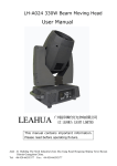
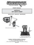
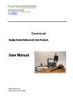
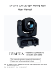
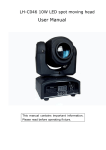
SERVICE MANUAL
MODE MP150 spot DV
CODE
ZL-013001-01
Address:Via Svizzera,12/14,Castel Goffredo Mantova 46042 Italy
Website: www.coef.it
INDEX
COVER-------------------------------------------------------------------------------------------------.1
INDEX--------------------------------------------------------------------------------------------------.2
1.0
SPECIFICATIONS---------------------------------------------------------------------3
2.0
CHANNELS AND DIGITAL VALUES---------------------------------------------4
3.0
ASSEMBLY SKETCH-----------------------------------------------------------------6
4.0
WIRE CONNECT DIAGRAM-------------------------------------------------------8
5.0
PCB COMPONENT LOCATION DRAWING-------------------------------------9
6.0
ASSEMBLY PARTS LIST------------------------------------------------------------10
7.0
ELECTRONIC MAINTENANCE--------------------------------------------------12
8.0 ORDINARY MAINTENANCE-----------------------------------------------------13
9.0
EXTRAORDINARY MAINTENANCE-----------------------------------------13
10.0 TROUBLE SHOOTING------------------------------------------------------------.15
COSTOMER SUPPORT REQUEST FORM-------------------------------------16
2
1.0 SPECIFICTION
l
l
l
l
l
l
l
l
l
l
l
l
l
l
l
l
l
l
Lamp: HSD 150/70-12.00 lumin
16 bit movement resolution –PAN 540 /TILT 270 with automatic repositioning
optical system with 3 lenses + dichroic reflector
11 colors + white + bi-color
5 rotating metal gobos all interchangeable + 2dichroic gobo
Adjustable strobe
Rainbow effect adjustable in speed
Focus adjustable
Black light filter
Shutter motorized
Multifunction display
Remote reset via DMX
Remote ON/OFF lamp via DMX
Software upgrade via DMX (with UNI-PROG 8 Accessory)
Automatic fault survey
Internal power factor correction
DMX 512 standard
Weight: 13Kg
Power supply
Volts
230V
3
Absorbed power
Hz
I
W
50Hz
0.9A
210 W
2.0 CHANNELS AND DIGITAL VALUES
4
8CHANNELS
CH
3
GOBOS
0 - 10
Neutral
11 - 20 GOBO1
chann.4
21- 30 GOBO2
chann.4
chann.4
31- 40 GOBO3
chann.4
41- 50 GOBO4
51- 60
Reduction
chann.4
61 - 70 GOBO5
chann.4
71 - 80 GOBO6
chann.4
81 - 90 GOBO7
chann.4
91 - 100 GOBO8
101 - 110 GOBO1
chann.4
chann.4
111 - 120 GOBO2
chann.4
121 - 130 GOBO3
chann.4
131 -140 GOBO4
chann.4
141 -150 GOBO5
chann.4
151 -160 GOBO6
chann.4
161 -170 GOBO7
chann.4
171 -180 GOBO8
181 -193 GOBOS Fast random
194 - 205 GOBOS Slow random
206 - 230 CW Rotation adjustment
231 - 255 CCW Rotation adjustment
9CHANNELS
GOBOS
0 -10
11- 20
21- 30
31- 40
41- 50
51- 60
61- 70
71- 80
81- 90
91 - 100
101 - 110
111- 120
121- 130
131- 140
141- 150
151- 160
161- 170
171- 180
181 - 193
194 - 205
206- 230
231- 255
controls rotation
controls rotation
controls rotation
controls rotation
controls rotation
controls rotation
controls rotation
controls rotation
controls position
controls position
controls position
controls position
controls position
controls position
controls position
controls position
Neutral
GOBO1
chann.4 controls rotation
chann.4 controls rotation
GOBO2
chann.4 controls rotation
GOBO3
chann.4 controls rotation
GOBO4
Reduction
chann.4 controls rotation
GOBO5
chann.4 controls rotation
GOBO6
chann.4 controls rotation
GOBO7
chann.4 controls rotation
GOBO8
chann.4 controls position
GOBO1
chann.4 controls position
GOBO2
chann.4 controls position
GOBO3
chann.4 controls position
GOBO4
chann.4 controls position
GOBO5
chann.4 controls position
GOBO6
chann.4 controls position
GOBO7
chann.4 controls position
GOBO8
GOBOS Fast random
GOBOS Slow random
CW Rotation adjustment
CCW Rotation adjustment
4
GOBOS ROTATION
0 - 5
STOP
6 - 255 From 0 to
GOBO positioning
6 - 130 CW Rotation adjustment of the GOBO
131 - 255 CCW Rotation adjustment of the GOBO
GOBOS ROTATION
0 - 5
STOP
6 - 255
From 0 to 540 GOBO positioning
6 - 130
CW Rotation adjustment of the GOBO
131 - 255 CCW Rotation adjustment of the GOBO
5
PAN MOVEMENT
PAN MOVEMENT
6
PAN MOVEMENT FINE ADJUSTMENT
PAN MOVEMENT FINE ADJUSTMENT
7
TILT MOVEMENT
TILT MOVEMENT
8
TILT MOVEMENT FINE ADJUSTMENT
TILT MOVEMENT FINE ADJUSTMENT
DIMMER
0 - 10
DIMMER CLOSED
11 - 250 DIMMER Adjustment
251 - 255 DIMMER OPEN
9
WARNING : position CHANNEL 1 at a value between 6 and 100,
in order to control DIMMER with this channel.
SPECIAL ACTION
When the lamp control via DMX(CDMX) and the RDMX function have been activated in the configuration menu. It is possible,
by a combination of the channels values, to control the lamp switch ON/OFF or to allow the projector MASTER RESET.
Lamp ON via DMX:
CHANNEL 2=value0
CHANNEL 3 and CHANNEL4= value 0 > 255 > 0
Lamp OFF via DMX:
CHANNEL2=value255
CHANNEL3 and CHANNEL4=value 0 > 255 > 0
MASTER RESET:
CHANNEL1=value0
CHANNEL 2 and CHANNEL3=value 0 > 255 > 0
5
1
7
2
8
3
4
6
Head sketch
9
10
11
12
5
13
14
6
3.0 ASSEMBLY SKETCH
CONTINUE
6
13
5
4
14
3
2
2
1
15
16
9
7
8
BOTTOM SKETCH
7
10
11
12
Arm sketch
4.0 WIRE CONNECT DIAGRAM
8
5.0 PCB COMPONENT LOCATION DRAWING
9
6.0 ASSEMBLY PARTS LIST
(Head)
R/N
P/N
PART NAME
DESCRIPTION
1
128-0210000001
lens
70 (0°/ 350°)
1
2
617-0130010000
lens assembly
56 (0°/ 500°)
1
3
617-0130010001
lens assembly
50(-250°/1200°)
1
4
610-0130010000
shutter/strobe blade
5
623-0130010000
reflector
6
126-0133001001
lampholder
G12 D-171B 6A 1000V L=280mm
1
7
605-0000000019
step motor
MH17H101-20
1
8
618-0130010001
gobo wheel assembly
133
1
9
611-0130010000
color wheel assembly
138*1.0
1
10
605-0000000024
step motor
MH17H101-10
3
11
624-0130010000
anti-heat filter assembly
1.0mm
1
12
088-5001063400
ignitor
4-5KV,5A HQCD-7
1
13
066-1120010000
safety thermic switch
14
083-0260000000
fan
91*40*0.5
1
85* *27*57
1
120
DC12V KD1206PTS L=330mm
10
QUA
1
1
continue
Bottom
R/N
P/N
PART NAME
DESCRIPTION
1
632-0130010000
measure place wheel
2
393-0103044706
step belt
3
119-0111000300
ballast
220V/110V 50HZ 1.8A 150W
1
4
044-1000000000
power socket
220V R-3013
1
5
041-2273000000
power switch
AC250V 16 4A 22*30
1
6
013-2000041000
capacitor
20UF J AC250V
1
7
088-5013001030
CPU pcb loaded
824B268725 160.15*95.35mm
1
8
088-5013001350
display pcb loaded
824B26873S 95.26*52.05mm
1
9
088-5013001491
optical sensor
23.18×17.15mm
1
10
022-1014022255
transformer
IN120V/230V21V2.0A )11.5V 1.2A
1
11
029-2100000000
AC-filter
110/250VAC/50-60HZ 6A
1
12
088-5013001130 DMX connect pcb loaded
824B2687AS 69.25*29.95mm
1
13
631-0130010000
plastic gear assembly
14
083-0270000000
fan
15
088-5013001480 encoder sensor pcb loaded
16
605-0000000020
70*0.5
HTD 447 3M6 CXP
step belt
11
114*9 120teeth
QUA
2
2
2
DC12V KDE1206PTVX L=120mm
1
04B498 L35.08*21.27mm
2
MH17H301-20
2
7.0 ELECTRONIC MAINTENANCE
This section is dedicated in detail to the electronic connection between the card and the mechanical components,assembled in the projector .These informations will be absolutely necessary when the mechanical
unit has to be removed from the projector for maintence and/or repair.
The connections are made using handy connectors and are detailed where you can find indications about the
connection beteween a specific connector and specific component of the mechanical unit. This includes the motors
and the sensors of the various effects wheels(color,gobos,shutter etc.)
WARNING! An improper use of this documentation made by not specifically qualified staff
can damage irremediably theelectronic and/or mechanical components of the projector
12
8.0 ORDINARY MAINTENANCE
Ordinary maintenance on the projector Mp150 spot DV is necessary to maintain the perfect
efficiency of the unit and to avoid defects like the low luminosity of the light beam or the elevated
overheating of the equipment
In the figures you can see those components that can easily accumulate dust and grease. Clean
them using a soft cloth and common glass-cleaners.
9.0 EXTRAORDINARY MAINTENANCE
15
13
After had access to the inside part of the projector(unscrew
the 5 screw(A) to take out the cover of the base to enter the
sensors of the PAN movement)special caution will be dedicated
to the sensors that put on a fundamental role in the operation of
the equipment. The sensors are indispensable in the moment of
the general reset of the projector, function that if not perform
correctly, harms in total manner the normal Operation of the
projector, at least for what pertains the group associated to the
sensors.
Maintain clean also all the openings that allow the convey of
the flows of air destined to the ventilation forced. The fan are in
general a catalysts for dust and fat and when these
deposet themselves On the pale of the same fan, the values and
the essential features change themselves and compromise the
good operation of the component destined to the cooling.
For the access to the parts of the arm (partcularly are present the sensors dedicated to the
TILT movement) unscrew the lives(B) and dismiss the cover in plastic of the arm.
The sensors of the relevant encoder of the PAN and TILT movements are located respectively in the base and in the arm of the Mp150 spot DV. The images illustrate clear these
components and where to intervine with precision for the intervention of maintence
14
10.0 TROUBLE SHOOTING
PROBLEM
The Projector doesn t switch on
The projector switches on but
doesn t answer to commands
CAUSE
ACTION
-The power supply is not present
Check if the luminous indicator is lighted
or not.
-The lamp is not working
Replace the lamp.
The thermal switch is active
Just to wait for little of time
-Wrong DMX configuration
Make sure that the projector is correctly
configurated.
-Defective cables
Replace or repair the DMX CABLE
-Defective control unit
Check the control unit by means of other
working projectors
Technical aid is required.
LED A is off
Defecting projection
Projectionb with halo
The color or other effects does
not coincide to the selected
value.
Check the control unit&DMX cable
-The lens is broken
Check that the lens are not broken
-Dust or grease stored on the all
parts of projector
Remove dust or grease stored on lenses
- Dust or grease stored on the all
parts of projector
-Position senser dirty with dust or
grease
- Defective motor
- Electronic board
The PAN movement does not - - Position senser dirty with dust or
coincide to the selected value grease
- Defective Motor
- Electronic board
Carefully clean the optical group lenses
and the projector components
Carefully clean the optical group lenses
and the projector components.
Technical aid is required.
Carefully clean the optical group lenses
and the projector components
Technical aid is required
15
COSTOMER SUPPORT REQUEST FORM
If you have any technical problem/malfunction and you need support, please fill in the
following form and send it by fax or e-mail directly to International Technical and Service
Department
The fax number is +086 0755 8209 0203
the e-mail address is [email protected] a better
problem comprehension you should fill in all the fields requested
Thank you.
Company name:
Contact person :
fax:
tel:
e-mail
Product indentification
Product name
code number ( * )
Time in use before fault:
Date of shipment to distributor:
Date of shipment to end user:
Operating conditions:
Mains supply voltage(volt):
main supply frequency(hertz):
Ambient temperature(¢J) :
Lamp type and manufacturer
Used in:
disc,
theatre,
serial number
Operating position:
rental,
other
Detailed description of product problem/requirement