1
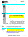
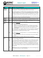
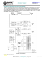
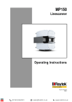
[email protected] [email protected] www.biopac.com PRODUCT SHEET MP150 SYSTEMS AVAILABLE MP150 STARTER SYSTEMS MP150 Licensed Systems – See corresponding license page for more information: System Windows Part # Mac Part # MP150 MP150WSW MP150WS MP150 plus Scripting MP150-WSW-BAS MP150-WS-BAS MP150 plus Network Data Transfer MP150WSW-NDT MP150WS-NDT MP150 plus Pressure Volume Loop Analysis MP150WSW-PVL MP150WS-PVL MP150 GLP MP150WSW-G MP150WS-G MP150 plus Developer Bundle MP150WSW-ENT MP150 plus 2-channel Vibromyography VMG102WSW VMG102WS MP150 plus 4-channel Vibromyography VMG104WSW VMG104WS MP150 System plus Baroreflex MP150WSW-BRS MP150WS-BRS MP150 System plus Actigraphy MP150WSW-ACT MP150WS-ACT System Upgrade – MP100 to MP150 MP150U-W MP150OU-M N/A The MP150 high-speed data acquisition system utilizes the very latest in Ethernet technology. The MP150 is compliant with any Ethernet (UDP) ready PC running Windows or Macintosh. This next generation product takes full advantage of cutting edge technology. Access multiple MP150 devices located on a local area network and record data to any computer connected to the same LAN. Record multiple channels with variable sample rates to maximize storage efficiency. Record at speeds up to 400 kHz (aggregate). MP150 System includes: Data acquisition unit: MP150A-CE Universal interface module: UIM100C AcqKnowledge® software CD License key (iLok USB) for AcqKnowledge 4.3+ Software Guide (PDF) Ethernet Connection ETHUSB Ethernet adapter and Crossover Cable: CBLETH2 See also: MP150 Specifications Power Supply: AC150A Recommended MP150 configuration For the best possible performance connect the MP System directly to the ETHUSB Ethernet USB adapter, via the CBLETH2 Ethernet crossover cable supplied with the system. This allows users to continue using an existing Ethernet card for accessing the Internet and local area network while using the MP System. If a computer does not require simultaneous connection to the network, standard crossover Ethernet cable can be used to connect the MP System to a computer. BIOPAC Hardware | MP150 Systems | Page 1 - 9 Updated: 2.25.2015 PRODUCT SHEET [email protected] [email protected] www.biopac.com MP150 SYSTEM SPECIFICATIONS Analog Inputs Number of Channels: Absolute Maximum Input: Operational Input Voltage: A/D Resolution: Accuracy (% of FSR): 16 ±15 V ±10 V 16 Bits ±0.003 Input impedance: 1.0 M Application Programming Interfaces options: Hardware Interface BHAPI Software Interface ACKAPI Analog Outputs Number of Channels: Max output with acquisition: Output Voltage Range: D/A Resolution: Accuracy (% of FSR): Output Drive Current: 2 2 channels ±10 V 16 bits ±0.003 ±5 mA (max) Output Impedance: 100 Digital I/O Number of Channels: Voltage Levels: Digital I/O Logic Type: Input Voltage Range: Input Clamp Current: Output Drive Current: External Trigger Input: Logic Level Thresholds: Input Low Voltage: Input High Voltage: 16 TTL, CMOS CMOS -0.5 V to 5.5 V (max) ±20 mA (max) ±20 mA (max) TTL, CMOS compatible - See also: External Trigger Inputs 1.50 V (max) 3.45 V (min) Time Base Min Sample Rate: Trigger Options: 2 samples/hour Internal, External or Signal Level Power Amplifier Module Isolation: CE Marking: Leakage current: Fuse: Provided by the MP unit, isolated clean power EC Low Voltage and EMC Directives <8 µA (Normal), <400 µA (Single Fault) 2 A (fast blow) Device specs MP150 Max Sample Rate MP Internal Memory: 200 K samples/sec (400 K aggregate) PC Memory/Disk: 200 K samples/sec (400 K aggregate) Internal Buffer: 6 M samples BIOPAC Hardware | MP150 Systems | Page 2 - 9 Updated: 2.25.2015 PRODUCT SHEET Device specs MP150 Waveform Output Buffer: 500 K samples Serial Interface Type/Rate: Ethernet: UDP (10M bits/sec) Transmission Type: Ethernet Maximum cable length: 100 meters (Ethernet cable) Power Requirements: 12 VDC @ 2 amp (uses AC150A) Dimensions: 10 cm x 11 cm x 19 cm Weight: 1.0 kg Operating Temperature Range: 0-70 C Operating Humidity Range: 0-95% OS Compatibility Ethernet Interface Windows Mac USB Interface Windows Mac [email protected] [email protected] www.biopac.com Windows XP, Vista, 7, 8 OS X Not supported Not supported ISOLATION Designed to satisfy the following Medical Safety Test Standards affiliated with IEC601-1: Creepage and Air Clearance Dielectric Strength Patient Leakage Current Contact BIOPAC for additional details. SIGNAL CONDITIONING MODULE COMPATIBILITY CO2100C EGG100C HLT100C PPG100C DA100C EMG100C LDF100C RSP100C EBI100C EOG100C MCE100C SKT100C ECG100C ERS100C O2100C STM100C EEG100C GSR100C OXY100C/E TEL100C CLEANING PROCEDURES Be sure to unplug the power supply from the MP150 before cleaning. To clean the MP150, use a damp, soft cloth. Abrasive cleaners are not recommended as they might damage the housing. Do not immerse the MP150 or any of its components, as this can damage the system. Let the unit air-dry until it is safe to reconnect the power supply. AC150/100A POWER SUPPLIES The 12-volt in-line switching transformer connects the MP unit to the AC mains wall outlet. One transformer is included with each MP System; replacements can be ordered separately. These transformers are specified to satisfy IEC60601-1 requirements and will accommodate 120-240 VAC (50/60 Hz) mains input. BIOPAC Hardware | MP150 Systems | Page 3 - 9 Updated: 2.25.2015 PRODUCT SHEET [email protected] [email protected] www.biopac.com MP150 SYMBOLOGY Front panel See “Light Status” section for functionality details. POWER Green light Indicates MP150 Power status. ACTIVITY Amber light Indicates data traffic to or from MP150— similar to Hard Disk activity light on any personal computer. BUSY Green light Indicates MP150 data acquisition. Power ON Push in to power up the MP150 OFF Pop out to cut the flow of power to the MP150 IMPORTANT! The MP150 does not have a “Hardware Reset” switch like a personal computer does. To reset the MP150 for any reason, turn the MP150 off, wait a few seconds, and then turn it back on. 2 Amp fast-blow fuse holder; the maximum capacity of the fuse is 2 Amps. To remove the fuse, use a screwdriver to remove the fuse cover, which is located below the word Fuse. Use the DC Input to connect a battery, AC/DC converter or other power supply to the MP150. The MP150 requires 12 VDC @ 1 Amp (minimum), 2 Amp (nominal) The receptacle can accept a “+” (positive) input in the center of the connector and a “” (negative) input on the connector housing. The MP150 connects to the computer via the Ethernet port, located just to the right of the word Ethernet. Uses a standard RJ-Ethernet connector (10 base T). Back panel Fuse 2A DC Input Ethernet Side panel Module connections The two connector inputs are designed to connect directly to the UIM100C. Analog signals are transmitted through the 37-pin connector (upper right side) Digital signals are transmitted through the 25-pin connector (lower-right side) Bottom Firmware Rollback Switch IMPORTANT! This is NOT A RESET SWITCH The Firmware Rollback Switch is located on the bottom of the MP150 unit and is recessed to prevent accidental activation—it is NOT A RESET for the MP150 unit. Warning! Activation of the Firmware Rollback Switch will cause the MP150 unit to operate under the previous version of firmware loaded into the unit. Refer to Appendix F of the AcqKnowledge Software Guide for procedural details. BIOPAC Hardware | MP150 Systems | Page 4 - 9 Updated: 2.25.2015 PRODUCT SHEET ACTIVITY BUSY A Bright B Bright MODE LIGHT STATUS DESCRIPTION Self-Test ACTIVITY and BUSY be bright for the duration of the self-test and setup process. This may take 3 – 10 seconds, depending on MP150 internal memory. Work Error A Bright B Blink A Blink B Bright A Blink B off Error Error Idle-1 Idle-2 A off [email protected] [email protected] www.biopac.com Self-Test B off During data acquisition, ACTIVITY reflects command/data traffic (for acquisition speeds of 1000 Hz or more, ACTIVITY will be permanently bright or blink at a high frequency) and BUSY will be bright. It is normal for both lights to be on—this does not indicate a problem unless an Error Message is generated on the computer screen. ERROR: In rare cases, a serious problem may prevent a self-test and the lights may be erratic: both on, both off, or any other static combination. The MP150 enters the Error Mode if a fatal error occurs during the Self-test Mode. In the Error Mode, ACTIVITY is bright and BUSY is blinking at a frequency of 5 Hz. If the self-test fails or setup fails, the Error mode is initiated and ACTIVITY will blink at about 5 Hz rate and BUSY will remain bright. ACTIVITY blinks twice with approximately 1.5-2 second interval and BUSY is OFF. Double blink means: - MP150 may be disconnected from LAN or, - MP150 is connected to LAN but did not receive IP address from network’s DHCP server and default 169.254.xxx.xxx address is self-assigned to MP150. This is the standard state for MP150 connected to NIC through crossover network cable. It means the MP150 is in working condition and ready for acquisition. AcqKnowledge may communicate with the MP150 through a serial cable or through a network by using 169.254.xxx.xxx address and/or crossover cable. ACTIVITY blinks once with approximately 1.5-2 second interval and BUSY is OFF. Single blink means: - MP150 is connected to LAN and received IP address from network’s DHCP server. It means the MP150 is in working condition and ready for acquisition. ACTIVITY and BUSY will go dark for less than 1 second at the end of the self-test before proceeding to the Idle mode. Wait Under some conditions, such as when a dialog box is open, AcqKnowledge cannot send commands to the MP150. When command flow from the workstation stops, the MP150 acts as if there is an open dialog and enters the Wait Mode to wait for a command from the workstation it is “locked” to—commands from any other work station will be ignored. When it receives a command, the MP150 return to the Work mode. After five minutes with no command communication, the MP150 will revert to the Idle mode. Error ERROR: In rare cases, a serious problem may prevent a self-test and the lights may be erratic: both on, both off, or a static combination. BIOPAC Hardware | MP150 Systems | Page 5 - 9 Updated: 2.25.2015 [email protected] [email protected] www.biopac.com PRODUCT SHEET MP150 STATUS LIGHT PATHS Startup (Power ON) > Self-test When the MP150 is turned ON, ACTIVITY and BUSY will shine for the duration of the self-test and setup process. This may take 3 – 10 seconds, depending on MP150 internal memory. Idle Error MP150 is waiting for any command/request from AcqKnoweldge or any workstation or any interface. [See Note 1] The MP150 enters the Error Mode if a fatal error occurs during the Self-test Mode. Work MP150 receives/sends commands/data to/from AcqKnowledge. [See Note 2] Wait MP150 cannot receive command due to software condition (i.e., dialog box open). [See Note 3] NOTES 1. IDLE—Both light patterns are normal and indicate that the MP150 is waiting for a command— neither indicates a problem with the MP150. The MP150 can switch between Idle-1 and Idle-2. Idle-1 or Idle-2 pattern indicates which IP address the MP150 is using: Idle-1: self-assigned address in 169.254.xxx.xxx network Idle-2: address from DHCP server). 2. WORK — When the MP150 receives any command from any workstation, it locks on to that workstation and communicates with it exclusively. The MP150 “remembers” the active workstation and will ignore commands from any other workstation. The MP150 usually remains in the Working Mode until the AcqKnowledge software program is closed. 3. WAIT — Under some conditions, such as when a dialog box is open, AcqKnowledge cannot send commands to the MP150. When command flow from the workstation stops, the MP150 acts as if there is an open dialog and enters the Wait Mode to wait for a command from the workstation it is “locked” to—commands from any other work station will be ignored. When it receives a command, the MP150 enters the Work mode; if the MP150 does not receive a command within five minutes, it reverts to Idle. BIOPAC Hardware | MP150 Systems | Page 6 - 9 Updated: 2.25.2015 PRODUCT SHEET [email protected] [email protected] www.biopac.com MP150A-CE DATA ACQUISITION UNIT BLOCK DIAGRAM The MP150 has an internal microprocessor to control the data acquisition and communication with the computer. There are 16 analog input channels, two analog output channels, 16 digital channels that can be used for either input or output, and an external trigger input. The digital lines can be programmed as either inputs or outputs and function in 8 channel blocks. Block 1 (I/O lines 0 through 7) can be programmed as either all inputs or all outputs, independently of block 2 (I/O lines 8 through 15). MP150A-CE block diagram See also: MP150 Specifications BIOPAC Hardware | MP150 Systems | Page 7 - 9 Updated: 2.25.2015 [email protected] [email protected] www.biopac.com PRODUCT SHEET MP SYSTEM PIN-OUTS — FOR MP150 Digital DSUB 25 (male) Pin-outs 1 2 3 4 5 6 7 14 15 16 17 18 19 8 9 10 11 12 13 20 21 22 23 24 25 DIGITAL Pin 1 2 3 4 5 6 7 8 9 10 11 12 13 Description I/O 0 I/O 1 I/O 2 I/O 3 GND D GND D EXT T +5 VD +5 VD I/O 8 I/O 9 I/O 10 I/O 11 Pin 14 15 16 17 18 19 20 21 22 23 24 25 Description I/O 4 I/O 5 I/O 6 I/O 7 GND A Out 1 Out 0 GND A I/O 12 I/O 13 I/O 14 I/O 15 Analog DSUB 37 (male) Pin-outs 1 2 3 4 5 6 20 21 22 23 24 25 7 8 9 10 11 12 13 14 15 16 17 18 19 26 27 28 29 30 31 32 33 34 35 36 37 ANALOG Pin 1 2 3 4 5 6 7 8 9 10 11 12 13 14 15 16 17 18 19 Description GND A GND A GND A GND A GND A GND A GND A GND A +12 V GND A -12 V GND A GND A GND A GND A GND A GND A GND A GND A Pin 20 21 22 23 24 25 26 27 28 29 30 31 32 33 34 35 36 37 Description CH 1 CH 2 CH 3 CH 4 CH 5 CH 6 CH 7 CH 8 +12 V - 12 V CH 9 CH 10 CH 11 CH 12 CH 13 CH 14 CH 15 CH 16 BIOPAC Hardware | MP150 Systems | Page 8 - 9 Updated: 2.25.2015 PRODUCT SHEET [email protected] [email protected] www.biopac.com ETHERNET CONNECTOR PIN-OUTS (FOR MODEL MP150 ONLY) Pin Description 1 TXD+ 2 TXD- 3 RXD+ 4 No Connection 5 No Connection 6 RXD- 7 No Connection 8 No Connection BIOPAC Hardware | MP150 Systems | Page 9 - 9 Updated: 2.25.2015