1
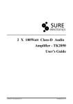
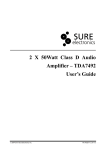
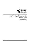
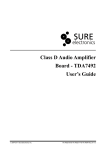
Serial Enabled Air Pressure
Sensor Module
User’s Guide
© 2004-2011 Sure Electronics Inc.
MB-SM11111_Ver1.0
BAROMETER MODULE
USER’S GUIDE
Table of Contents
Chapter 1. Overview ..........................................................................................................1
1.1 Overview .............................................................................................................. 1
1.2 Features ............................................................................................................... 1
1.3 Applications......................................................................................................... 1
Chapter 2. Hardware Detail ...............................................................................................2
2.1 Pin Description.................................................................................................... 2
Chapter 3. Electrical Characteristics ...............................................................................3
3.1
3.2
3.3
3.4
3.5
3.6
3.7
Operating Conditions of MS5561....................................................................... 3
Operating Conditions of Module ....................................................................... 3
Digital Inputs........................................................................................................ 4
Digital Outputs..................................................................................................... 4
Pressure Output Characteristics ....................................................................... 4
Temperature Output Characteristics ................................................................. 5
Typical Characteristics ....................................................................................... 5
Chapter 4. SPI Interface.....................................................................................................8
Chapter 5. UART Interface ..............................................................................................12
5.1
5.2
5.3
5.4
UART Configuration.......................................................................................... 12
UART Command................................................................................................ 13
Examples ........................................................................................................... 13
How to Use......................................................................................................... 14
Chapter 6. Mechanical Drawing......................................................................................15
Chapter 7. Notes ..............................................................................................................16
Chapter 8. Contact Us .....................................................................................................17
© 2004-2011 Sure Electronics Inc.
MB-SM11111_Ver1.0_Page i
Serial Enabled Air Pressure Sensor Module
NOTES:
Product Version
:
Ver 1.0
Document Version
:
Ver 1.0
MB-SM11111_Ver1.0_Page ii
© 2004-2011 Sure Electronics Inc
SERIAL ENABLED AIR PRESSURE
SENSOR MODULE
USER’S GUIDE
Chapter 1. Overview
1.1 Overview
Thanks for purchasing the air pressure sensor module by Sure Electronics. This module
is an accurate pressure and temperature measuring device utilizing MS5561 sensor and
PIC16F690. Pressure and temperature values can be directly obtain via SPI or UART
interface on the module, eliminating complicated calculation process. Original calibration
data can be directly obtained from MS5561. It allows for use of other microprocessors to
do operations to MS5561.
A DIP-like design is adopted facilitating system integration.
FIGURE 1-1 OVERVIEW
Note: All the diagrams in this manual are for reference only.
1.2 Features
y
DC 3.3V or 5V power supply
y
SPI interface & UART interface
y
High measurement accuracy and stability
y
DIP-like packaging facilitates integration
1.3 Applications
y
Mobile phones
y
GPS receivers
y
Altimeter applications
y
Personal Navigation Devices (PND)
y
Digital cameras with altimeter function
© 2004-2011 Sure Electronics Inc.
MB-SM11111_Ver1.0_Page 1
SERIAL ENABLED AIR PRESSURE
SENSOR MODULE
USER’S GUIDE
Chapter 2. Hardware Detail
2.1 Pin Description
TABLE 2-1 PIN DESCRIPTION
Pin
Mark
1
32.768 KHz
Function
sensor clock
input
Selection of SPI
and UART
interface. When
this pin is given
2
SPISEL
low level, UART
is available.
When this pin is
given high level,
SPI is available.
3
RX
4
TX
5,6,7,8,14,16,
Receive
Serial Data
Transmit
NC
Not connected
9
SCL
SPI serial clock
10
SDO
SPI data output
11
SDI
SPI data input
12
+5V
+5V supply
GND
Ground
+3.3V
+3.3V supply
18
TOP
Serial Data
13,15,17,19,
20,23,24
21,22
Note:
1. Do not use 5V and 3.3V power supply simultaneously.
2. To all pins on the module, 3.3V is high level and 0V is low level.
MB-SM11111_Ver1.0_Page 2
© 2004-2011 Sure Electronics Inc.
SERIAL ENABLED AIR PRESSURE
SENSOR MODULE
USER’S GUIDE
Chapter 3. Electrical Characteristics
3.1 Operating Conditions of MS5561
TABLE 3-1 PARAMETERS
Parameter
Symbol
Supply voltage
VDD
Storage temperature
TS
Overpressure
P
Conditions
Min
Ta = 25 °C
-
Max
Unit
Notes
-0.3
4
V
-
-40
+85
°C
1
-
10
bar
-
Ta = 25°C
Note: Storage and operation in an environment of dry and non-corrosive gases.
3.2 Operating Conditions of Module
TABLE 3-2 PARAMETERS (TA = 25°C, VDD = 3.0 V OR 5V)
Parameter
Symbol
Conditions
Min.
Typ
Max
p
-
10
-
1100
Operating pressure
range
Supply current,
average
(1)
conversion
during
Iavg
(2)
-
Isc
Iss
MCLK = 32.768
consumption into
kHz
(3)
Operating
T
temperature range
signal (4)
tconv
μA
MCLK = 32.768
kHz
-
-
0.5
μA
-40
+25
+85
°C
-
-
35
ms
MCLK
-
30.000
32.768
35.000
kHz
-
-
40/60
50/50
60/40
%
SCLK
-
-
-
500
kHz
Duty cycle of MCLK
Serial data clock
mA
1
0.1
Current
External clock
abs.
μA
4
conversion)
Conversion time
mbar
VDD = 3.0 V
standby (no
MCLK
Unit
Note:
1. Under the assumption of one conversion every second. Conversion means either a
pressure or a temperature measurement started by a command to the serial
interface of MS5561.
2.
During conversion the sensor will be switched on and off in order to reduce power
consumption; the total on time within a conversion is about 2 ms.
3.
4.
It can be reduced by switching off MCLK while MS5561 is in standby mode.
It is strongly recommended that a crystal oscillator be used because the device is
sensitive to clock jitter. A square-wave form of the clock signal is a must.
© 2004-2011 Sure Electronics Inc.
MB-SM11111_Ver1.0_Page 3
Serial Enabled Air Pressure Sensor Module
3.3 Digital Inputs
TABLE 3-3 PARAMETERS (T = - 40°C TO 85°C, VDD = 3.3 V OR 5V)
Parameter
Symbol
Conditions
Min
Typ
Max
Unit
Input High Voltage
VIH
-
2.64
-
3.3
V
Input Low Voltage
VIL
-
0
-
0.66
V
Signal Rise Time
tr
-
-
200
-
ns
Signal Fall Time
tf
-
-
200
-
ns
3.4 Digital Outputs
TABLE 3-4 PARAMETERS (T = - 40°C TO 85°C, VDD = 3.3V OR 5V)
Parameter
Symbol
Conditions
Min
Typ
Max
Unit
Output High Voltage
VOH
Isource = 0.6 mA
2.64
-
3.3
V
Output Low Voltage
VOL
Isink = 0.6 mA
0
-
0.66
V
Signal Rise Time
tr
-
-
200
-
ns
Signal Fall Time
tf
-
-
200
-
ns
3.5 Pressure Output Characteristics
With the calibration data stored in the interface IC of the MS5561, the following
characteristics can be achieved :( VDD = 3.0 V unless noted otherwise)
TABLE 3-5 PARAMETERS
Parameter
Resolution 1
Absolute Pressure
Accuracy
2
Relative Pressure
Accuracy
3
Conditions
Min
Typ
Max
Unit
-
0.1
-
mbar
-1.5
-
+1.5
mbar
-0.5
-
+0.5
mbar
-1
-
+1
mbar
-2
-
+3
mbar
12 months
-
-1
-
mbar
-
-1.6
-
+1.6
mbar
p = 300 to 1000 mbar
Ta = 25°C
p = 750 to 1100 mbar
Ta = 25°C
p = 750 to 1100 mbar
Ta = 25°C
T = 0 to +50°C
Relative Pressure Error
over Temperature 4
p = 300 to 1000 mbar
T = -40 to +85°C
p = 300 to 1000 mbar
Long-term Stability 5
Maximum Error over
Supply Voltage
Note:
1. A stable pressure reading of the given resolution requires taking the average of 2
to 4 subsequent pressure values due to noise of the ADC.
2.
Maximum error of pressure reading over the pressure range.
3.
Maximum error of pressure reading over the pressure range after offset adjustment
at one pressure point.
4.
With the second-order temperature compensation as described in Section
“FUNCTION". See next section for typical operating curves.
5.
MB-SM11111_Ver1.0_Page 4
The long-term stability is measured with non-soldered devices.
© 2004-2011 Sure Electronics Inc
Electrical Characteristics
3.6 Temperature Output Characteristics
This temperature information is not required for most applications, but it is necessary to
allow for temperature compensation of the pressure output.
TABLE 3-6 PARAMETERS
Parameter
Conditions
Min
Typ
Max
Unit
Resolution
-
0.005
0.01
0.015
°C
T = 20°C
-0.8
-
0.8
°C
T = -40 to +85°C
-2
-
+3
°C
VDD = 2.2V to 3.6 V
-0.2
-
+0.2
°C
Accuracy 1
Maximum Error over
Supply Voltage 2
Note:
1. With the second-order temperature compensation as described in Section
2.
“FUNCTION". See next section for typical operating curves.
At Ta = 25 °C
3.7 Typical Characteristics
FIGURE 3-1 ADC-VALUE D1 VS PRESSURE (TYPICAL)
FIGURE 3-2 ADC-VALUE D2 VS TEMPERATURE (TYPICAL)
© 2004-2011 Sure Electronics Inc.
MB-SM11111_Ver1.0_Page 5
Serial Enabled Air Pressure Sensor Module
FIGURE 3-3 ABSOLUTE PRESSURE ACCURACY
FIGURE 3-4 TEMPERATURE ERROR ACCURACY VS TEMPERATURE (TYPICAL)
FIGURE 3-5 PRESSURE ERROR ACCURACY VS TEMPERATURE (TYPICAL)
MB-SM11111_Ver1.0_Page 6
© 2004-2011 Sure Electronics Inc
Electrical Characteristics
FIGURE 3-6 PRESSURE ERROR VS SUPPLY VOLTAGE (TYPICAL)
FIGURE 3-7 TEMPERATURE ERROR VS SUPPLY VOLTAGE (TYPICAL)
© 2004-2011 Sure Electronics Inc.
MB-SM11111_Ver1.0_Page 7
SERIAL ENABLED AIR PRESSURE
SENSOR MODULE
USER’S GUIDE
Chapter 4. SPI Interface
FIGURE 4-1 EXTERNAL MCU CONNECTION SCHEMATIC (ON-BOARD MCU USED)
With:
M_SDO = Serial Data Out
M_SDI = Serial Data In
M_SCL = Serial Clock
32768HZ = Oscillator at 32.768 kHz for MS5561
SPISEL= External microcontroller selection
When SPISEL is given low level, on-board microcontroller is used to do operations to
MS6651 (as shown in figure 4-1). When SPISEL is given high level, you can use an
external microcontroller to do operations to MS6651 (as shown in figure 4-2). When an
external microcontroller is used, the on-board MCU doesn’t work. Following is the
process.
Example: reading calibration words 2 and 4 on a MS5561
MB-SM11111_Ver1.0_Page 8
© 2004-2011 Sure Electronics Inc.
Serial Enabled Air Pressure Sensor Module
FIGURE 4-2 EXAMPLE: READING CALIBRATION WORDS 2 AND 4 ON A MS5561
The frame to be sent is 1-1-1-0-1-0-1-1-0-0-0-0 (for calibration word 2)
With SPI protocol, it is only possible to send 8 bits at a time (one byte). The frame must
be divided by two and some “0” must be placed before and after the frame to complete
the two bytes.
It becomes: 0-0-0-1-1-1-0-1-0-1-1-0-0-0-0-0
Separated in bytes: 0-0-0-1-1-1-0-1¦0-1-1-0-0-0-0-0
In Hexadecimal: 1Dh 60h
FIGURE 4-3 CALIBRATION FOR WORD 2
Note: The 0 added after the frame is placed to have one more clock after the stop bits
on the SCLK line.
The other frames become:
Conversion start for pressure measurement (D1): 0Fh & 40h
Conversion start for temperature measurement (D2): 0Fh & 20h
Read calibration word 1 (W1): 1Dh & 50h
Read calibration word 2 (W2): 1Dh & 60h
Read calibration word 3 (W3): 1Dh & 90h
Read calibration word 4 (W4): 1Dh & A0h
Reset sequence command: 15h & 55h & 40h
With SPI protocol, two parameters need to be checked or adjusted during the
configuration of microcontroller’s SPI module:
- Clock Idle state must be low.
- Transmission must occur on rising edge of the serial clock when the microcontroller
wants to send data received by the sensor. On the other side, when the microcontroller
wants to receive data sent by the sensor transmission must occur on the falling edge of
the clock.
© 2004-2011 Sure Electronics Inc.
MB-SM11111_Ver1.0_Page 9
SPI Interface
FIGURE 4-4 TRANSMISSION
FIGURE 4-5 FLOW CHART FOR PRESSURE AND TEMPERATURE READING AND
SOFTWARE COMPENSATION
Note:
1. Readings of D2 can be done less frequently, but the display will be less stable in
this case.
2. For a stable display of 0.1 mbar resolution, it is recommended to display the
average of 8 subsequent pressure values.
MB-SM11111_Ver1.0_Page 10
© 2004-2011 Sure Electronics Inc
Serial Enabled Air Pressure Sensor Module
FIGURE 4-6 ARRANGEMENT (BIT PATTERN) OF CALIBRATION DATA IN WORD1
TO WORD4
In order to obtain best accuracy over the whole temperature range, it is recommended to
compensate for the non-linearity of the output of the temperature sensor. This can be
achieved by correcting the calculated temperature and pressure by a second order
correction factor. The second-order factors are calculated as follows:
FIGURE 4-7 FLOW CHART FOR CALCULATING THE TEMPERATURE AND
PRESSURE TO THE OPTIMUM ACCURACY
© 2004-2011 Sure Electronics Inc.
MB-SM11111_Ver1.0_Page 11
SERIAL ENABLED AIR PRESSURE
SENSOR MODULE
USER’S GUIDE
Chapter 5. UART Interface
With:
M_SDO = Serial Data Out
M_SDI = Serial Data In
M_SCL = Serial Clock
32768HZ = Oscillator at 32.768 kHz for MS5561
SPISEL= External microcontroller selection
RXD= Serial Data Receive
TXD= Serial Data Transmit
When SPISEL is given low level, on-board microcontroller is used to do operations to
MS6651 (as shown in figure 4-1). When SPISEL is given high level, you can use an
external microcontroller to do operations to MS6651 (as shown in figure 4-2). When an
external microcontroller is used, the on-board MCU doesn’t work. Following are details
of UART communication.
FIGURE 5-1 UART COMMUNICATION CONNECTION SCHEMATIC
5.1 UART Configuration
Baud rate: 9600bps
Start bit: 1bit
Data bit: 8bits
Parity bit: 0bit
Stop bit: 1bit
Note: UART level is COMS level. High level is 3.3V and low level 0V.
MB-SM11111_Ver1.0_Page 12
© 2004-2011 Sure Electronics Inc.
Serial Enabled Air Pressure Sensor Module
5.2 UART Command
TABLE 5-1 COMMAND SET
Command
T
Function
Output the current temperature value. Temperature in °C is displayed in
the first line. Temperature in ℉is displayed in the second line.
P
Output the current air pressure with the unit of Pa.
H
Output the current height
T-C
Output temperature value in °C
T-F
Output temperature value in ℉
TEST
Test mode. Serial port keeps on outputting temperature in °C and the
current air pressure.
Note:
y
All UART commands shall start with ”$sure” and followed by a space (0x20) and
end with enter (0x0d, 0x0a).
y
y
y
y
All UART commands shall be expressed in ASCII.
All UART commands are not case-sensitive.
Altitude is gotten when sea level is one standard air pressure. If sea level is not one
standard air pressure, the altitude won’t be accurate but only relative height will be
obtained. For example, the altitude of location A is 50m and altitude of location B is
90m, B is relatively 40m higher than A. The tolerance is 10m.
In Test mode, pressing any key can exit.
5.3 Examples
1.
Current Temperature
$sure t
Temperature(C & F):
0016.8 Celsius
0062.2 Fahrenheit
2.
Current Air Pressure
$sure p
Air pressure:1010.9 mbar
3.
Current Height
$sure h
Height:00020 meters
4.
Current Temperature in °C
$sure t-c
Temperature(C):0018.3 Celsius
5.
Current Temperature in ℉
$sure t-f
Temperature(F):0065.3 Fahrenheit
6.
Test Mode
$sure test
Enter auto sending mode, press any key to exit
Air pressure:1011.1 mbar
Temperature(C):0018.3 Celsius
Air pressure:1011.1 mbar
© 2004-2011 Sure Electronics Inc.
MB-SM11111_Ver1.0_Page 13
UART Interface
Temperature(C):0018.3 Celsius
Air pressure:1011.1 mbar
Temperature(C):0018.3 Celsius
Air pressure:1011.1 mbar
Temperature(C):0018.3 Celsius
k The auto sending mode has exited
7.
Bad Command
If commands entered are wrong, it will return Bad command!
For example:
$sure kl
bad command!
5.4 How to Use
a.
Power the module.
b.
Send commands to the module via the port. For example, send $sure P to the module
and then the current air pressure will be displayed on the computer.
FIGURE 5-2 OBTAIN THE CURRENT AIR PRESSURE
MB-SM11111_Ver1.0_Page 14
© 2004-2011 Sure Electronics Inc
SERIAL ENABLED AIR PRESSURE
SENSOR MODULE
USER’S GUIDE
Chapter 6. Mechanical Drawing
FIGURE 6-1 MECHANICAL DRAWING
© 2004-2011 Sure Electronics Inc.
MB-SM11111_Ver1.0_Page 15
SERIAL ENABLED AIR PRESSURE
SENSOR MODULE
USER’S GUIDE
Chapter 7. Notes
Humidity and Water Protection
This module is designed for the integration into portable devices and sufficiently
protected against humidity. A silicone gel for enhanced protection against humidity
covers the membrane of the pressure transducer. The module must not be used for
under water applications.
Light Sensitivity
The MS5561 is protected against sunlight by its metal cap. It is, however, important to
note that the sensor may still be slightly sensitive to sunlight, especially to infrared light
sources. This is due to the strong photo effect of silicon. As the effect is reversible there
will be no damage, but the user has to take care that in the final product the sensor
cannot be exposed to direct light during operation.
MB-SM11111_Ver1.0_Page 16
© 2004-2011 Sure Electronics Inc.
SERIAL ENABLED AIR PRESSURE
SENSOR MODULE
USER’S GUIDE
Chapter 8. Contact Us
Sure Electronics Co., Ltd.
East zone, 3F, Building 6
Jingang Technology Innovation Center
No.108 Ganjiabian Rd (ZIP: 210000)
Qixia District
Nanjing
P.R.China
Tel:
+86-25-68154800-860
Fax:
+86-25-68154891-832
Website:
www.sure-electronics.com
Email:
[email protected]
© 2004-2011 Sure Electronics Inc.
MB-SM11111_Ver1.0_Page 17