1
™
USER GUIDE
™
*If the ESC does not count the correct number of cells, as indicated by the
beeps, then your cutoff voltage will NOT work. Do NOT fly. First, ensure your
battery is fully charged. If the problem persists please contact customer
support.
Note: if auto-calibrate throttle (default throttle setting) is selected, always
restrain vehicle and run throttle to full power prior to flight to allow ESC to
recognize the full throttle signal.
Note: Always power your radio transmitter before powering up the
receiver and/or the ESC. Some receivers with failsafe features or receiver
units that are not bound on receiver power up are entirely capable of
causing the arming sequence to occur and command the ESC to drive the
motor. Always keep the aircraft restrained and clear of body parts when
the ESC is powered.
Always perform a range check at full, half, and zero throttle before flying
with any new speed controller!
IMPORTANT WARNINGS
•Castle Creations is not responsible for your use of this product or
for any damage or injuries you may cause or sustain as a result of
its usage.
•Castle controllers are for use by adults only.
•Always remove the propeller or pinion when working on a power
system with the battery connected.
•Please observe all local laws regarding the flying of remote control
aircraft.
•Never fly over others or near crowds.
•An RC vehicle crash or a power system malfunction may result in
fire. Never operate RC vehicles in a flammable environment, such
as around dry vegetation.
HOW TO CONNECT YOUR TALON
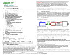
1. Add Your Battery Connector
You must solder a quality battery connector of your choice to the red (+) and
black (-) power wires. Solder the battery connector to the wires. ENSURE
THAT THE POLARITY IS CORRECT (red wire to battery red wire, black
wire to battery black wire). Follow the instructions provided with the
battery connector.
2. Connect The Motor To Your ESC
Solder Castle male bullet connectors to the motor and Castle female
connectors (barrel) to the motor leads attached to the ESC. Connect the
motor to the ESC by pushing the bullet connectors into the barrels, swap any
two connections to reverse the rotation of the motor.
3. Connect The ESC To Your Receiver
Connect the receiver lead to the throttle channel on your receiver.
Note to users with external receiver/radio power supply: Always disconnect
the red power wire on the throttle lead if an external BEC or battery is
employed in the radio/servo circuit.
Note to users with a Futaba transmitter: You must reverse the throttle
channel signal on your transmitter. Please refer to your Futaba instructions
and exercise extreme caution when first powering your ESC.
OPERATION
The Castle Talon ESC will not provide power to the motor when first powered
up. The ESC must receive a low throttle signal to arm.
Follow this initialization sequence to operate the motor.
1. Turn your transmitter ON and set the throttle stick to mid throttle.
TALON ESC PROGRAMMABLE FEATURES
Talon ESCs offer a wide array of operating modes and settings for helicopter,
multi-rotor, and fixed wing vehicles. These settings are most readily
accessed using the Castle Link USB adapter (coupon for free Castle Link
USB adapter is included with the Talon ESC) and Castle Link User Interface
software available at no charge at castlecreations.com/downloads.
TALON ESC STICK PROGRAMMING
You may change the following settings using your transmitter and receiver.
Low Voltage Cutoff Value
ESC optionally stops or ramps down the motor power when the input battery
voltage drops to the programmed cutoff voltage per cell. Values include, 3.0,
3.1, 3.2, 3.3, 3.4 volts per cell or NONE.
Brake
ESC optionally stops rotation of the motor when the throttle signal is moved
to the lowest position. Values include soft delayed brake, hard delayed brake,
soft immediate brake, hard immediate brake, and brake disabled.
Low Voltage Cutoff Type
Select the method of cutoff employed by the Talon when the low voltage
set in #1 is reached. Options are hard cutoff, soft cutoff, RPM decrease, and
pulsing RPM.
PWM Settings
Choose a PWM rate that best suits your motor. Options are 8 kHz, 12 kHz, or
16 kHz.
MANUALLY CHANGING PROGRAMMABLE SETTINGS
The Talon ESC software is designed to make it difficult to accidentally
enter programming mode. Once in programming mode, the Talon ESC “asks”
questions by beeping and flashing the setting number, followed by the
number for each of the setting values. You must answer “yes” or “no” by
moving the throttle stick on your transmitter to each of the setting values as
the Talon ESC presents them. The values are always presented in sequence.
This method does NOT “tell you” what any of the settings are currently
programmed for.
The current setting and setting value are “flashed” out by the LED. (For
example if you are on setting #3 and value #2, there will be 3 beeps/flashes,
then 2 beeps/flashes repeating until you answer). Answering “no” to a
setting value will cause the Talon ESC to ask for the next value in sequence.
Answering “yes” to a setting value will store that setting in the permanent
memory, and skip to the next setting.
2. If you are using an external BEC or radio battery and your red power wire
on the throttle lead is disconnected, power the radio receiver in the RC
vehicle.
NOTE: If you answer “no” to all values for a particular setting, the ESC will
keep whatever value had been previously programmed. Only by answering
“yes” to a value will the Talon ESC store/change any value.
3. Connect the main power battery to the speed controller. The ESC will
make a chime and then a sequence of beeps. Count the number of beeps
and make sure it matches the number of LiPo cells that were plugged
into the unit.* The speed controller will remain disarmed and will not
operate the motor until it receives the zero throttle command from the
receiver.
You will need to move the transmitter stick to the “yes” (full throttle) position
or the “no” (zero throttle) position to answer the question. When the Talon
ESC has accepted your answer, it will flash the LED rapidly, and emit a
constant beeping. Move the throttle stick back to the middle position for the
next question.
4. When you are ready to fly, move the throttle stick to the lowest position
on your transmitter.
After you have verified that the controller works properly, follow the steps
below to change settings.
5. The Talon will play the arming tone through the motor to indicate that it
is armed.
If you only wish to change some of the settings you do not need to continue
through the programming steps for the remaining settings. To exit stick
programming mode at any point, disconnect battery power, re-connect
power, and arm the speed control as normal.
Setting 3: Low Voltage Cutoff Type
Option
Value
Recommended Use
1
Hard
Cutoff
Will shut the motor off when the programmed cutoff
voltage is reached. The motor may be restarted
by lowering the throttle to the brake position, and
re-arming. For gliders and some parkflyers where
a “motor off” situation does not put the model in
danger.
2. Connect a motor battery to the Talon ESC and the ESC will sound its
initialization tones. After a short period of time the Talon ESC will sound
another short tone and the LED will flash a short, single flash that
repeats. NOTE: If the ESC flashes continuously it is not seeing a full
throttle position. Move your throttle trim to the top position or increase
your full throttle endpoint or ATV on your transmitter.
2
Soft
Cutoff
ESC ramps down the throttle to safely maintain the
battery voltage at the programmed cutoff level. Very
useful for 3D flying, indoor flying, all helicopters,
and most any sport flying where you do not want
the motor to turn off when the low voltage cutoff is
reached. FACTORY setting.
3. Move your transmitter stick to the middle position. The ESC will sound
another short tone, and the LED will flash a short, double flash that
repeats.
3
RPM
decrease
ESC reduces RPM dramatically.
4
Pulsing
RPM
ESC pulses throttle
ENTER PROGRAMMING MODE
1. The Talon ESC must be connected to a motor in order for you to hear the
programming beeps. Turn your transmitter on, and leave the Talon ESC
unpowered. Move the transmitter stick to the top position (full throttle).
4. Move your transmitter stick back to the top position again. After a short
time, the ESC will sound a short tone, and the LED will flash a short, triple
flash that repeats.
5. Move your transmitter stick back to the middle position again. The ESC
will sound four short tones in a row, and the LED will start a repetitive
flash sequence consisting of a single flash, a pause, another single flash,
followed by another pause.
The ESC is now in programming mode and asking you if you would like to
set the first option (Low Voltage Cutoff) to the first value (3.0V). Enter your
settings using the method described on the other side.
Setting 1: Auto-LiPo volts/cell cutoff*
NOTE: When setting LiPo cutoff voltage, always follow your battery brand
recommendations.
Option
Value
1
3.0V per cell
2
3.1V per cell
3
3.2V per cell
4
3.3V per cell
5
3.4V per cell
6
DISABLED
Recommended Use
Note: Options 3 and 4 will give a warning that the battery pack is below
the preset low voltage level. The ESC will allow the user to run the motor
without additional action. The user is responsible for stopping further
discharge of the battery.
Setting 4: PWM Switching Rate**
Option
Value
Recommended Use
1
8kHz
Suggested for most Scorpion outrunners.
2
12 kHz
Recommended for most brushless motors.
FACTORY setting.
3
16 kHz
Recommended for low inductance motors. RARE.
Suggested for Kontronik Tango motors.
**Refer to motor manufacturer’s instructions for frequency settings.
CONTACT AND WARRANTY INFO
FACTORY setting
Controller will NOT shut down motor at any
voltage.
*Refer to cell vendor’s instructions for cutoff voltage.
Setting 2: Brake Type
Option
Value
Recommended Use
1
Soft Delayed
Brake
General aircraft use, with fixed or folding prop.
2
Hard
Delayed
Brake
Direct drive applications where more braking
power is required.
3
Soft Brake –
No Delay
Competition use where a very short brake delay
is required.
4
Hard Brake–
No Delay
Competition use where a very short brake delay
is required. Brake action may be very abrupt. Be
very cautious with high-powered setups.
5
Brake
Disabled
Helicopters, 3D airplanes, and by choice, on most
aerobatic airplanes. FACTORY setting.
Your Talon ESC is warranted for one year* from date of purchase to be
free from manufacturing and component defects. This warranty does not
cover abuse, neglect, or damage due to incorrect wiring, over voltage, or
overloading. If you have any questions, comments, or wish to return your ESC
for warranty or non-warranty repair or replacement, contact Castle Creations,
Inc. at:
Phone: (913) 390-6939
540 North Rogers Road
Olathe, Kansas 66062 USA
www.castlecreations.com
*You may have additional warranty rights under the laws of certain nations
or states.
NON-WARRANTY REPAIRS
Never throw away a damaged Castle product! You may send it to Castle and
take advantage of our flat price replacement offer. Please check our website
for specific pricing.
TALON ESC OPERATIONAL TONES AND ERROR CODES
Tone
Talon LED
Meaning
Description
Castle power
tune with beeps
corresponding to
number of cells
Blinks out cell-counts
with RED LED
Power up notice
ESC plays Castle signature tone and beeps out the number of cells attached to controller.
Note: when Auto-LiPo detect is disabled by the user, ESC will not beep the number of cells.
Arming tune
N/A
ESC ready to run motor
ESC plays the Castle arming tone once it receives a low throttle signal from the receiver.
Controller is ready to run the motor at this point.
•
RED LED matches tones
Powered ESC notice
ESC beeps motor every 10 seconds to remind user that power is connected to the ESC. This
notice may be disabled in Castle Link.
•-
RED LED matches tones
Low voltage cutoff
Main battery voltage dropped below the cutoff value. Default is Auto-LiPo which generates
a value using 3.2V times the detected cell count. Other settings may be entered in Castle
Link.
•- •
RED LED matches tones
Over temperature
ESC reached an overtemp condition when operated under too high a load, operated
without proper cooling airflow, or when operated at partial throttle (40%-99%) with too
large a load.
•- -
RED LED matches tones
Excessive load
ESC detected very high current spikes. Causes may include damaged wiring leading to or in
the motor, or the use of too large a motor for the controller.
••
•••••
-•
- •-
RED LED matches tones
Start fail
ESC was unable to start motor
RED LED matches tones
Radio glitch
ESC detected unusual signals or loss of signal on throttle wire.
RED LED matches tones
Motor anomaly
ESC detected a sudden mechanical interruption of the motor’s rotation.
RED LED matches tones
Over-current
ESC detected operating currents that exceed the current rating of the ESC.
Red LED matches tones
BEC over temperature
ESC has detected that the integrated BEC is overheating due to current draw above the
ratting of the BEC.
None
Flashing GREEN LED
Locked head speed
Governor mode has locked the head speed.
None
SOLID RED
Full throttle
ESC is at full throttle.
ESC will not run motor until it receives an arming signal from radio via the throttle lead.
© 2013 Castle Creations, Inc.
= SHORT TONE
KEY •- = LONG TONE
Revision Date - 09/2013