1
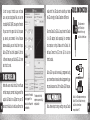
CASTLE
DRIVER’S
ED
Instruction manual for all Castle Creations
Car and Truck Brushless Power Systems
WARNING : This is an extremely powerful brushless motor system. We strongly recommend
removing your pinion gear for your own safety and the safety of those around you before
performing calibration and programming functions with this system. Please keep your hands, hair,
pets, fuzzy purple shorts and garden gnomes clear from the gear train and wheels of an armed
high performance system.
Rubber tires will “grow” to extreme size on a high speed vehicle. D O N O T hold the vehicle in the air and run
it up to full throttle. Tire failures at speed can cause serious injury! Make sure your tires are securely glued
to the rims and check them often!
Always disconnect the battery from the ESC when you are finished using your vehicle. The switch on the ESC
controls the power that is delivered to the receiver and servos. The controller will always draw current
when it is connected to the battery and will completely discharge batteries if they are connected for long
durations. This may cause failure of your batteries.
Your Castle ESC is programmed to sound a tone every thirty seconds to remind you that it is still powered. It
will also sound a warning tone every five seconds when it is powered but receiving no radio signal.
Quick Start Guide
1. Solder a high quality battery connector to the ESC.
2.Mount the ESC and motor into the car.
3.Plug in the 3 motor wires to the 3 motor wires on the ESC.
4.Plug in the ESC Rx lead to CH2 on your receiver.
5.Make sure the ESC’s switch is off.
6.Plug in a battery.
7.Holding full throttle on your transmitter, turn the switch ON.
A.After a few seconds you’ll hear multiple tones and the red LED will come on.
B.Now hold full brake and after a few seconds you’ll hear multiple tones and the yellow LED
will come on.
C. Now relax to neutral and after a few seconds you’ll hear multiple tones and ALL the LEDs
will light up.
D.A few seconds later the ESC will arm with a double tone and you’re ready to go!
Contents
Usage Warning.. . . . . . . . . . . . . . . . . . . . . . . . . . . . 2
ESC Setup.. . . . . . . . . . . . . . . . . . . . . . . . . . . . . . . . 13
o o3.
Reverse Amount.. . . . . . . . . . . . . . . . . . 24
Troubleshooting.. . . . . . . . . . . . . . . . . . . . . . . . 36
Quick Start Guide.. . . . . . . . . . . . . . . . . . . . . . . . 3
How To Calibrate The ESC.. . . . . . . . . . . . . . . 14
o o4.
Punch/Traction Control.. . . . . . . . . . 25
Technical Support.. . . . . . . . . . . . . . . . . . . . . . 39
Introduction.. . . . . . . . . . . . . . . . . . . . . . . . . . . . . 6
Castle Link Set-up.. . . . . . . . . . . . . . . . . . . . . . 17
o o5.
Drag Brake.. . . . . . . . . . . . . . . . . . . . . . . 27
Contact & Warranty Info... . . . . . . . . . . . . 39
Connections.. . . . . . . . . . . . . . . . . . . . . . . . . . . . . . 8
To Use Castle Link.. . . . . . . . . . . . . . . . . . . . . 18
o o6 .
Dead Band.. . . . . . . . . . . . . . . . . . . . . . . . 28
Programming Reference.. . . . . . . . . . . . . . . 42
Manual Programming.. . . . . . . . . . . . . . . . . . . . 19
o o7.
Cutoff Voltage.. . . . . . . . . . . . . . . . . . . 29
o o8 .
Motor Timing.. . . . . . . . . . . . . . . . . . . . . . 32
o o9.
Motor Type. . . . . . . . . . . . . . . . . . . . . . . . 34
o oBrushless
o oBrushed
4
Motor Wiring.. . . . . . . . . . . . . . 8
Motor Wiring.. . . . . . . . . . . . . . . . 10
Radio Connection.. . . . . . . . . . . . . . . . . . . . . . . 12
o o1 .
Brake/Reverse Type.. . . . . . . . . . . . . . . 22
o o2 . Brake
Amount.. . . . . . . . . . . . . . . . . . . . . 23
5
Easy to Use, Sophisticated Enough to Win Everything
Castle controllers are extremely simple to set up and optimize for your application. Most users
may simply plug the controller into their motor, radio and battery and run it immediately.
Advanced users may wish to access the incredible tuning features using their Windows based
PC and the Castle Link interface (sold separately) or the provided USB cable for Mamba Max.
With the Castle Link software, you can tune the ESC exactly with point and click ease!
Please make sure to read this manual completely to get the most from your Castle ESC.
A Word About Batteries And Connectors
6
As with any extremely high powered electric power system, the primary limitations to ultimate
vehicle performance are the batteries and connectors. Use the best batteries and connectors
that you can find. The better the batteries, the more punch you’ll have! H i n t : L o o k for t h e
b a t t e r i e s w i t h t h e l ow e s t r e s i s t a n c e , n o t n e c e s s ar i ly t h e c o o l e s t l a b e l s.
Top-of-the-line cells aren’t required for this system to operate normally, but the best cells
will certainly allow your Castle system to put more power to the ground!
Poor quality battery connectors can be a roadblock to performance. Avoid the common “white
plastic” connectors commonly seen on many battery packs. A fast brushless setup will draw
many times the power that these connectors can safely handle. Invest in connector sets made
for high powered electric systems such as our CC Bullets or Deans Ultra plugs.
Power Wiring
Your Castle ESC has motor connectors on the motor wires and the battery input wires are bare.
You must add the connector of your choice to the battery leads. We recommend a connector
rated for 40-100amps, such as CC Bullets, Deans Ultra or Astro Flight Zero Loss.
Proper polarity is essential here! Make absolutely sure positive (+) connects to positive (+),
and negative (-) connects to negative (-) when you plug in your battery! If reverse polarity is
7
applied to your ESC from the battery,
it WI L L damage your ESC. T h i s WI L L
N O T b e c o v e r e d u n d e r w ar r a n t y!
BRUSHLESS MOTOR
WIRING DIAGRAM
Battery
Pack
Brushless
Motor
CONNECTIONS
Brushless Motor Wiring
8
(See Figure 1: Brushless Motor Setup)
For brushless motor connection, the
three wires from the ESC to the motor
have no polarity. Connect the red,
white and black motor wires to the
three wires coming from the motor.
If you are using a motor other than a
Castle Creations CM36 motor, you may
Steering
Servo
Use a high quality
connector only
(not included)
Connect
controller
and motor
using
supplied
connectors
Steering
Servo
in CH1
Receiver
CASTLE ESC
Connect
Castle ESC to throttle
in CH2
channel
Figure 1: Brushless Motor Setup
On/Off
Switch
need to either solder on matching male bullet plugs to your motor, or solder the ESC wires
directly to the motor wires.
If you choose to direct solder or to shorten the motor wires, you may do so on the Castle
Creations CM36 motors only. D O N O T CU T any part of the wire length from any other motor,
regardless of brand or type. In most cases, only the last 1/4 inch or so of most motor wires is
able to be soldered . If they are clipped shorter you may not be able to solder the remaining
portion of the wire and the motor will not run properly, if at all. If the motor is supplied
with connectors you do not want to use, simply unsolder the original motor connectors from
the wires - do not cut them off.
There is no polarity on the three ESC-to-motor wires, so do not worry about how you connect
them initially. You may find it necessary to swap two wires if the motor runs in reverse. This
will be explained below.
9
Brushed Motor Wiring
Reversing Brushed Motor Mode:
(See Figure 2: Reversing Brushed
Motor Setup) Use this mode if you
wish to use reverse. Use only the red
and black motor wires from the ESC. In
most applications, the red wire from
the ESC will connect to the red wire
(or p o s i t iv e + side hood) on your
motor, and the black wire to the black
wire (or n e g a t iv e - side hood) of
the motor. The white motor wire is not
used. After calibration, (explained
below) you may need to swap the two
10 motor wires to get the wheels to spin
REVERSING
BRUSHED MOTOR
WIRING DIAGRAM
Battery
Pack
Use a high quality
connector only
(not included)
Steering
Servo
Brushed
Motor
Red ESC
motor wire
to Motor (+)
Black ESC
motor wire
to Motor (-)
HIGH POWER
BRUSHED MOTOR
WIRING DIAGRAM
Steering
Servo
in the right direction.
Battery
Pack
Use a high quality
connector only
(not included)
Battery (+)
to
Motor (+)
Brushed
Motor
Motor
Tab
(+)
Motor
Tab
(-)
White motor
wire not used
Steering
Servo
in CH1
Steering
Servo
in CH1
Castle ESC
in CH2
Connect
to throttle
channel
Figure 2: Reversing Brushed Motor Setup
CASTLE ESC
Receiver
CASTLE ESC
Receiver
All ESC
motor wires
to Motor (-)
Castle ESC
in CH2
On/Off
Switch
Connect to
throttle
channel
On/Off
Switch
Figure 3: High Power Brushed Motor Setup
High Power Brushed Motor Mode:
(See Figure 3: High Power Brushed Motor
Setup) Connect all three of the ESC motor
wires to the negative (-) side of the motor.
You can either use a “Y” harness from the
ESC battery input positive wire to connect
to both the battery and the positive side
of the motor, or use a single wire from the
positive ESC input to the positive battery
pole and then continue to the positive (+)
side of the motor.
11
Radio Connection
Your Castle ESC plugs into the throttle channel of your receiver. This is usually channel 2.
Your Castle ESC provides 5 volts to the receiver to power the receiver and the steering servo.
No separate receiver battery is needed to power the radio system.
Castle ESC receiver plugs are made to be used with any receiver, so you will need to make sure
the polarity is correct. The signal wire is orange, the positive wire is red, and the negative
is brown. Some radio systems use white for signal, red for positive and black for negative
color scheme. Check your receiver documentation for correct connection polarity if it’s not
marked. (Most receivers use negative to the outside of the case and signal towards the inside
of the case.)
12
ESC SETUP
ESC / Radio Calibration
Individual transmitter’s signals for neutral, full and full brake vary. You must calibrate your
Castle ESC so that it will operate most effectively with your transmitter. Anytime the ESC is
powered up with a new transmitter, or with different throttle channel settings, it will need to
be calibrated to “know” what the transmitter’s throttle settings are. It will also need to be
calibrated after updating with new software via Castle Link.
If y o u ar e u s i n g a Fu t a b a or Fu t a b a O EM b r a n d t r a n sm i t t e r, y o u w i l l n e e d
t o s e t t h e t r a n sm i t t e r’s t h r o t t l e c h a n n e l d i r e c t i o n t o t h e R E V ER S E (R e v)
p o s i t i o n . T h i s i s e i t h e r a n e x t e r n a l m i c r o sw i t c h o n t h e t r a n sm i t t e r or
a n o p t i o n a v a i l a b l e w i t h i n t h e c om p u t e r pr o g r amm i n g o f t h e t r a n sm i t t e r’s
throttle channel.
13
Please start by zeroing out any throttle trim that you may have set in your transmitter.
D o n’ t p l u g i n t h e b a t t e r y y e t ! Make sure that the battery polarity and input polarity on
the ESC are correct. Check the on/off switch of the Castle ESC to make sure that it is in the
OFF position (“ON” is marked in small letters on one side).
W e r e c omm e n d r em o v i n g y o ur p i n i o n g e ar b e for e c a l i b r a t i o n a s a s a fe t y
pr e c a u t i o n !
How to Calibrate the ESC
STEP 1 : Start with the transmitter ON and the ESC switched OFF and not connected to the
battery.
STEP 2 : Plug a battery into your Castle ESC.
14
STEP 3 : Hold full throttle on the transmitter and turn the ESC’s switch ON. Keep holding full
throttle on the transmitter. If all your connections are correct, you will hear one multi-toned
initialization “ring” from the motor (all tones are played by the ESC vibrating the motor).
STEP 4 : After a second or two, the green LED on the ESC will blink rapidly and the motor will
“ring” 4 times rapidly in a row (accepting the full throttle endpoint). After the green LED
flashes and tones, the ESC will blink the red LED. At this point the full throttle endpoint has
been set within the ESC and now it’s looking for the full brake endpoint (red LED blinking).
STEP 5 : Move the throttle trigger to the full brake position and hold full brake. After a
few seconds, the ESC will flash the red LED and ring 4 times rapidly (accepting full brake
endpoint).
STEP 6 : After accepting the full brake endpoint the ESC will then blink the yellow LED. Now
relax the trigger to the neutral position. The ESC will now ring 4 times and flash the yellow
LED rapidly to accept the neutral position.
15
After accepting the neutral position, the ESC will ring twice and flash ALL the LEDs. This is
the arming tone and LED indication that the ESC IS NOW ARMED and the car will respond to
throttle inputs from your transmitter.
From this point on, when you connect batteries and turn the switch on, the ESC will give the
initialization tone and flash after a battery is plugged in and the switch is turned on, and
the arming tone will ring a second or two later. If the ESC is programmed for the Auto-Lipo
setting, it will beep the number of cells in your Lipo pack between the initialization tones and
the arming tones. After the arming tone plays, the ESC is ACTIVE and will respond to throttle
application.
If you have problems calibrating your transmitter with the Castle ESC, please see the
troubleshooting guide on page 37 for more tips. Once you are calibrated and armed, do one
last check before going out and experiencing the Castle brushless difference. Slowly advance
16 the throttle and check the rotation direction of the motor and the color of the LEDs on the
ESC. If the motor is spinning in the right direction and the GREEN LED is blinking green, then
you are ready for a test run before going into the settings of the ESC. If the ESC shows the
green LED with throttle, but the wheels spin in the wrong direction, you’ll need to switch any
two of the motor wires (example: switch from red to red and black to black to red to black
and black to red).
CASTLE Link set-up
Your Mamba Max ESC comes with a USB cable and a CD
with the Castle Link installation software.
Other Castle ESCs may be linked with the optional
Castle Link USB adapter (sold separately).
The Castle Link software will give you access to a
whole new world of tuning options. You may use Castle
17
Link to tune your throttle curve and brake
curve, set your drag brake feel, and use the
incredible PUNCH CONTROL to keep the front end
of your car on the ground with all the power
you have at your command. As new features
become available, you can install them in your
Castle ESC for “real time” updates! All of this
is free and ensures your Castle ESC will be the
best that it can be.
small end of the USB cable to the side of your Mamba
Max ESC and enjoy the Castle Creations difference!
All other Castle Car ESCs will require that the Castle
Link USB adapter (sold separately) be connected
to a computer running Windows and the Castle Link
software. Connect the ESC to the USB Link via the
throttle cable.
Castle ESCs may also be manually programmed using
your transmitter and receiver. Manual programming may
not provide access to all of the Castle ESC’s features.
To use CASTLE LINK
Mamba Max users should install the software
on their computer, connect the large end of the
supplied USB cable to a USB port on your PC,
18 and start the Castle Link software. Connect the
Screen shot of the basic
settings page of the
Castle Link software for
the Mamba Max
The brake and throttle
response curves are fully
manipulatable
Manual Programming
Follow these steps to change settings on your Castle
CASTLE LINK CONNECTIONS
USB
USB cable connects
your PC directly to
Mamba Max for tuning
via Castle Link software
CASTLE
LINK
CASTLE ESC
Castle Link USB adapter connects your
Castle ESC to a USB cable for tuning
via Castle Link software
on your Windows PC
19
ESC without a computer.
Remove your pinion gear before calibration and manual programming as a safety precaution!
STEP 1 : Start with the transmitter ON and the ESC switched OFF and not connected to the
battery.
STEP 2 : Plug a battery into the ESC. Hold full throttle on the transmitter and turn the ESC
switch ON. After a few seconds you will get the four rings in a row signaling full throttle
calibration. Keep on holding full throttle. After a few more seconds, you will hear another
four rings in a row. After the second group of four rings, relax the throttle to neutral. If
you have successfully entered programming mode, the ESC will beep twice, pause, and repeat
the two beeps.
20
STEP 3 : The programming sequence is always presented in sequential order and always starts
with the first setting (Reverse Lockout) within the first section (Reverse Type). The first
beep(s) signifies which section of the programming you are in and the second beep(s) signifies
which setting is waiting for a “yes” or “no” answer.
As you go sequentially through the options, you will need to answer “yes” by holding full
throttle, or answer “no” by holding full brake until the ESC accepts your answer by beeping
rapidly. Once an answer has been accepted, relax the throttle back to neutral for the next
question. After a “no” answer is accepted, the ESC will then present you with the next option
in that section. After a “yes” answer is accepted, the ESC knows you aren’t interested in any
other option in that section, so it skips to the first option in the next section.
Settings & Explanations
The Castle ESC is extremely flexible and may be “tuned” like any other part of your car or
truck. The following section explains all the settings available to you via manual programming
and what each one does to change the reactions of the ESC in order to tune it to your specific
preferences. More settings are available via Castle Link.
21
1. Brake / Reverse Type
2. Brake Amount
Sets whether reverse is enabled or not, and exactly how it can be accessed.
Sets what percentage of available braking power is applied with full brake.
Setting 1 : Reverse Lockout (Default)
This setting allows the use of reverse only after the ESC senses two seconds of neutral
throttle. Use it for race practice sessions and bashing, but check with your race director to
see if this setting is allowed for actual racing.
Setting 1 : 25% Power
Allows only 25% of available braking power at full brake.
Setting 2 : Forward/Brake Only
Use this setting for actual sanctioned racing events. Reverse cannot be accessed under any
circumstances with this setting.
Setting 3 : Forward/Brake/Reverse
Reverse or forward is accessible at any time after the ESC brakes to zero motor RPM (if the
22 vehicle is moving).
Setting 2 : 50% Power (Default)
Allows only 50% of available braking power at full brake.
Setting 3 : 75% Power
Allows 75% of available braking power at full brake.
Setting 4 : 100% Power
Allows all available braking power at full brake.
23
24
3. Reverse Amount
4. Punch/ Traction Control
Sets how much power will be applied in the reverse direction, if reverse is enabled.
Setting 1 : 25% Power
Allows only 25% power in reverse.
This setting controls how fast the throttle position within the ESC can be changed over
time. This smooths high power starts and limits punch somewhat. As explained previously,
acceleration is a matter of battery capability, but you may not want 100% of what the battery
can deliver in every situation.
Setting 2 : 50% Power (Default)
Allows only 50% power in reverse.
This setting is crucial to drag racing as it can be used as a “traction control” to match
traction conditions.
Setting 3 : 75% Power
Allows only 75% power in reverse.
The lower the setting, the less throttle change limiting there is. For pure burnout and wheelie
action, use a very low setting or the disabled setting. For softer acceleration or for a lowgrip surface, raise it up to a higher setting.
Setting 4 : 100% Power
Allows 100% power in reverse.
Don’t be afraid to use these settings! It may be fun to watch your car do back flips, but sooner
25
or later you are going to want to be able to drive it under some semblance of control.
This is TH E setting to put you back into control.
asphalt, and 2WD vehicles on asphalt.
Setting 1 : High
Very limited acceleration. Good for 2WD vehicles on hard dirt, or for general bashing when
you want to be gentle on the transmission.
Setting 5 : Disabled (Default)
Acceleration is only limited by battery ability. This setting is good for 4WD sedans on carpet,
high traction drag racing, or bashing where unlimited wheelie power is desired.
Setting 2 : Medium
Medium acceleration limiting. Good for 2WD vehicles on soft dirt, and 4WD vehicles on hard
dirt.
Setting 3 : Low
Light acceleration limiting. Good for 4WD vehicles on soft dirt.
Setting 4 : Lowest
26 Very light acceleration limiting. Good for most situations including 4WD vehicles on dirt and
5. Drag Brake
Sets the amount of drag brake applied at neutral throttle to simulate the slight braking
effect of a neutral brushed motor while coasting.
Setting 1 : Drag Brake OFF (Default)
Vehicle will coast with almost no resistance from the motor at neutral throttle.
Setting 2 : Drag Brake 10%
Low amount of braking effect from the motor at neutral throttle.
27
Setting 3 : Drag Brake 20%
More braking effect from the motor at neutral throttle.
Setting 1 : Large - 0.1500 ms
Setting 4 : Drag Brake 30%
Fairly high braking effect from the motor at neutral throttle.
Setting 3 : Small - 0.0750 ms
Setting 5 : Drag Brake 40%
High braking effect from the motor at neutral throttle.
6. Dead Band (NEW!)
You may adjust the neutral throttle “width” of the controller with this setting. Smaller
values make the controller enter forward or brake/reverse with a smaller movement of your
throttle trigger for finer control. Be careful, some transmitters offer better resolution
than others, if your ESC will not respond to “Neutral” throttle, make this setting larger.
28
Setting 2 : Normal - 0.1000 ms (Default)
Setting 4 : Very Small - 0.0500 ms
Setting 5 : Smallest - 0.0250 ms
7. Cutoff Voltage
Sets the voltage at which the ESC lowers or removes power to the motor in order to either
keep the battery at a safe minimum voltage (Lithium Polymer cells) or the radio system working
reliably (NiCad/NiMH cells).
Setting 1 : None (Default)
Does not cut off or limit the motor due to low voltage. Do not use with any Lithium Polymer
29
packs!
Applications: Any racing or bashing situation with 6-8 cell NiCad or NiMH packs.
Use this setting ONLY with NiCad or NiMH packs. With continued driving, the radio system
may eventually cease to deliver pulses to the servo and ESC, and the vehicle will not be
under control.
Yo u w i l l i r r e v e r s i b ly d am a g e L i t h i um P o lym e r p a c k s w i t h t h i s s e t t i n g !
Setting 2 : Auto-Lipo
This setting allows you to go back and forth between 2 and 3 cell lipo packs without having
to change the cutoff voltage for each one. The ESC automatically sets the cutoff voltage
correctly for a 2 or 3 cell pack when that pack is plugged in.
Setting 3 : 5v
30 Cuts off/limits the motor speed/acceleration when the pack gets down to 5 volts. A good
setting for racing or bashing in any vehicle using 8-12 NiMH or NiCad packs.
Setting 4 : 6v
Cuts off/limits acceleration when the pack gets down to 6 volts.
A MU S T U S E s e t t i n g for 2 c e l l (7.4v) L i t h i um P o lym e r p a c k s. Yo u w i l l
i r r e v e r s i b ly d am a g e y o ur p a c k s u s i n g a l ow e r c u t o ff v o lt a g e !
Setting 5 : 9v
Cuts off/limits acceleration when the pack gets down to 9 volts.
A MU S T U S E s e t t i n g for 3 c e l l (1 1 .1 v) L i t h i um P o lym e r p a c k s. Yo u w i l l
i r r e v e r s i b ly d am a g e y o ur p a c k s u s i n g a l ow e r c u t o ff v o lt a g e !
31
Setting 6 : 12v
Cuts off/limits acceleration when the pack gets down to 12 volts.
A MU S T U S E s e t t i n g for 4 c e l l (1 4.8 v) L i t h i um P o lym e r p a c k s. Yo u w i l l
i r r e v e r s i b ly d am a g e y o ur p a c k s u s i n g a l ow e r c u t o ff v o lt a g e ! U s e o f a 4
c e l l L i P o p a c k i s c o v e r e d u n d e r w ar r a n t y ON LY o n M o n s t e r M a x E S C s.
8. Motor Timing
Advancing the timing on an electric motor can have varying effects. Lowering the timing
advance will reduce the amp draw, increase runtime, reduce motor/battery temperature, and
may slightly reduce top speed and punch. Raising the timing advance will increase amp draw,
decrease runtime, increase motor/battery temperature, and may slightly increase top speed
and punch.
32
If you are after maximum top speed, it’s better to “gear up” to get it rather than advance the
timing too far.
For brushed motors, always keep this setting on NORMAL and use the end bell of the motor to
“tweak” it to max RPM per the motor’s instructions.
Setting 1 : Lowest
A maximum efficiency setting giving long runtimes and cooler motor temps. Very useful with
high Kv (low turn) motors to increase motor life and reduce motor/battery temperatures.
Setting 2 : Normal (Default)
The best mix of speed, punch, and efficiency for all motors.
Setting 3 : Highest
Increases amp draw, reduces runtimes, increases motor/battery temperatures, and may
increase top speed/punch slightly.
33
U s e w i t h c ar e , a n d m o n i t or m o t or a n d b a t t e r y t em p s o f t e n ! D O N O T u s e
a n y s e t t i n g a b o v e “ n orm a l” w i t h 6 0 0 0Kv or h i g h e r m o t or s.
9. Motor Type
This setting sets which type of motor you will be using with the Castle ESC. The ESC may be
damaged if this setting does not match the motor type/hook-up method in the car, and this
damage is not covered under warranty.
Setting 1 : Brushless (Default)
(See Figure 1: Brushless Motor Setup on page 8) Uses all three of the ESC motor wires
connected to all three of the brushless motor wires. If the motor spins the wrong way with
forward throttle, swap any two of the wires to get the correct direction.
34
Setting 2 : Brushed Reversing
(See Figure 2: Reversing Brushed Motor Setup on page 10) Uses the Red and Black ESC motor
wires to connect to the (+) and (-) side of the brushed motor. If the motor spins in the wrong
direction with forward throttle, reverse the motor wires for correct motor direction.
Setting 3 : Brushed High Power
(See Figure 3: High Power Brushed Motor
Setup on page 11) Connect all three of the
ESC motor wires to the negative (-) side of
the motor. You can either use a “Y” harness
from the ESC battery input positive wire to
connect to both the battery and the positive
side of the motor, or use a single wire from
the positive ESC input to the positive battery
pole and then continue to the positive (+)
side of the motor.
35
Troubleshooting
If you’re still having difficulties with your Castle ESC after trying the suggestions offered
here, please contact Castle Creations technical support at the e-mail or phone number in the
next section.
36
Problem: My ESC cal i brates for the ful l throttle and ful l brake positi ons
but won’t cal i brate to the neutral throttle positi on (yel low LED keeps
flashi ng).
Problem: My Castle ESC may or may not arm, but it wi l l not cal i brate to
my transmitter.
Solution: Try moving the throttle trim one way, then the other (usually towards the throttle
side is best). If your transmitter has a 50/50 and 70/30 setting for the throttle, set it for
50/50 and retry calibration. Also, if you have changed the dead band to a narrower band you
may want to try going back to the “normal” setting.
Solution: Most calibration issues can be solved by changing settings on the transmitter. Make
sure you have both your throttle and brake endpoints (called EPA or ATV on your radio) on the
throttle channel out to between 100 to 120%. Make sure if you have a Futaba or Futaba made
transmitter to have the throttle channel set to the reversed position.
Problem: My vehi c le ac ts l i ke it has “turbo lag” (poor accelerati on/punch
for the fi rst few feet or yards, and then it “k i cks i n”).
Solution: Make sure you’re using high quality batteries and a battery connector capable of
high amp flow (40-100 amps). This behavior is very typical of a battery pack that is having
37
difficulty providing the power your vehicle/system requires for top performance.
Use copper bars to connect cells rather than welded tabs. Copper bars have a much lower
resistance.
Problem: My batter y pack i s plugged i nto the ESC and nothi ng i s work i ng
- no steer i ng and no throttle.
Solution: Make sure the ESC’s receiver plug is plugged into channel 2 on the receiver, and that
it’s plugged in with the correct orientation. Double check your solder connections on the
battery plug, and make sure the battery is showing good voltage.
Look for more troubleshooting tips on the Castle Creations website at:
38
www.castlecreations.com/support/faq.html
Technical support
You may contact our world class technical support department 24/7 via e-mail, or from 9am to
5pm Central time Monday through Friday.
E-mail: [email protected]
Phone: (913) 390-6939
Contact & Warranty Info
Your Castle ESC is warranted for one (1) year from date of purchase to be free from
manufacturing and component defects. This warranty does not cover abuse, neglect, or damage
due to incorrect wiring, over voltage, or overloading. If you have any questions, comments, or
wish to return your Castle ESC for warranty or non-warranty repair or replacement, please
contact Castle Creations, Inc.
39
Castle Creations, Inc.
40
235 South Kansas Avenue, Olathe, Kansas 66061 USA
www.castlecreations.com
Phone: (913) 390-6939
41
CASTLE CAR ESC PROGRAMMING REFERENCE
1: Brake/Reverse Type
3: Reverse Amount
5: Drag Brake
Option 1: Reverse Lockout (D)*
Option 2 : Forward/Brake Only
Option 3 : Forward/Brake/Reverse
Option
Option
Option
Option
Option
Option
Option
Option
Option
1 : 25%
2 : 50% (D)*
3 : 75%
4 : 100%
2: Brake Amount
Option
Option
Option
Option
1 : 25%
2 : 50% (D)*
3 : 75%
4 : 100%
4: Punch Control
Option
Option
Option
Option
Option
1 : High
2 : Medium
3 : Low
4 : Lowest
5 : Disabled (D)*
1 : Disabled (D)*
2 : 10%
3 : 20%
4 : 30%
5 : 40%
6. Throttle Dead Band
8: Motor Timing
Setting
Setting
Setting
Setting
Setting
Option 1 : Lowest
Option 2 : Normal (D)*
Option 3 : Highest
1 : Large - 0.1500 ms
2 : Normal - 0.1000 ms (D)*
3 : Small - 0.0750 ms
4 : Very Small - 0.0500 ms
5 : Smallest - 0.0250 ms
7: Voltage Cutoff
Option
Option
Option
Option
Option
Option
1 : None (D)*
2: Auto-Lipo
3: 5
4: 6
5: 9
6 : 12
9: Motor Type
Option 1 : Brushless (D)*
Option 2 : Brushed Reversing
Option 3 : Brushed High Power
*Denotes Default Setting
Revision date - 11/2007
P/N: 095-0012-00
© 2007 Castle Creations, Inc.