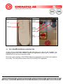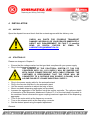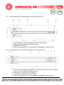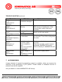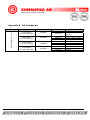
1
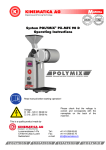
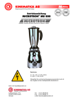
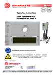
Operating Instructions for POLYTRON® System PT 7100 VOLTAGE 230 V, 50/60 Hz Ensure that the supply voltage is correct and in agreement with the data on the rating plate. This is a quality product of Luzernerstrasse 147a CH-6014 Luzern Switzerland Tel.: Fax: e-mail: +41-41-259 65 65 +41-41-259 65 75 [email protected] TABLE OF CONTENT: 1 INTRODUCTION .......................................................................................................... 3 1.1 1.2 1.3 2 SAFETY .......................................................................................................................7 2.1 2.2 2.3 2.4 3 POLYTRON DISPERSING-AGGREGATES ...................................................... 15 TECHNICAL SPECIFICATIONS.......................................................................... 17 INSTALLATION ......................................................................................................... 18 4.1 4.2 5 SUMMARY ............................................................................................................ 7 SAFETY CONCEPT .............................................................................................. 7 RESIDUAL DANGERS ........................................................................................ 10 WARNINGS ......................................................................................................... 11 DESCRIPTION OF THE EQUIPMENT ....................................................................... 13 3.1 3.2 4 OPERATING INSTRUCTIONS .............................................................................. 3 ORGANISATIONAL MATTERS ............................................................................. 5 WARNING NOTICES ............................................................................................ 6 UNPACK ............................................................................................................. 18 STARTING UP..................................................................................................... 18 MAINTENANCE ......................................................................................................... 19 5.1 5.2 DRIVE ................................................................................................................. 20 CLEANING AND MAINTENANCE OF THE AGGREGATES................................ 20 6 TROUBLE SHOOTING .............................................................................................. 23 7 ACCESSORIES ......................................................................................................... 24 8 WARRANTY ............................................................................................................... 25 APPENDIX A. DIMENSIONAL DRAWINGS ................................................................ 26 APPENDIX B. BILL OF MATERIALS .......................................................................... 28 Operating Instructions PT 7100 english / Release 1.0 / 20.09.2006 page 2 of 28 1 INTRODUCTION This chapter gives information on the the structure of this document. It will assist you in making use of it and show how to find the required information quickly. 1.1 OPERATING INSTRUCTIONS PLEASE READ THESE OPERATING INSTRUCTIONS BEFORE SWITCHING ON OR OPERATING THE EQUIPMENT. THEY DESCRIBE THE USE OF THE POLYTRON PT 7100, ITS INSTALLATION AND MAINTENANCE AND THE APPROPRIATE REPLACEMENT PARTS AND ACCESSORIES. THEY WILL HELP YOU AVOID ERRONEOUS USE AND SUBSEQUENT DAMAGE. ALTHOUGH POLYTRON UNITS ARE DESIGNED FOR EASE OF SERVICE, THIS DOES NOT RELEASE YOU FROM THE OBLIGATION TO INSPECT YOUR EQUIPMENT CAREFULLY AND TO CLEAN IT THOROUGHLY. KINEMATICA AG is a specialist manufacturer of machines and equipment for dispersion and mixing technology. An important objective of these operating instructions is to fully inform you, the user, about the correct and safe use of our equipment. In order to achieve this, it is essential that you should carefully study chapter 2, “Safety”, and follow the instructions in this book. Operating Instructions PT 7100 english / Release 1.0 / 20.09.2006 page 3 of 28 1.1.1 RANGE OF VALIDITY The information in these operating instructions relates to the POLYTRON® identified as follows: Manufacturer: Brand name: Product name: Order No. 21006009 21006006 21006007 21006008 KINEMATICA AG, CH-6014 Luzern POLYTRON® POLYTRON® PT 7100 Identification POLYTRON® PT 7100 drive, 230V, US & JP (*) (and other countries with 100..115V supply) POLYTRON® PT 7100 drive, 230V, with CH-plug POLYTRON® PT 7100 drive, 230V, with EU-plug POLYTRON® PT 7100 drive, 230V, with GB-plug (*)REMARK: The version of the POLYTRON® System PT 7100 for countries with 100…115V supply will be shipped not with cable connectors but with cable strands. The customer is responsible that the drive will be connected to a suitable 230V source (1-phase), such as one phase of 3-phase industrial supply. Operating Instructions PT 7100 english / Release 1.0 / 20.09.2006 page 4 of 28 1.1.2 TARGET AUDIENCE These operating instructions are intended for all authorised users of our machines/equipment. We distinguish different user roles, taking account of the different demands placed on the user by the activity to be carried out. You will find the definitions of user roles with the demands on the user in chapter 2, “Safety”. You can fulfil one or more of these roles, provided that you meet the corresponding demands. 1.2 ORGANISATIONAL MATTERS If you are unable to find the answer to any question in the operating instructions, please contact the equipment manufacturer directly. 1.2.1 LOCATION OF THE OPERATING INSTRUCTIONS The operating instructions can only be of use to you if you always have them at hand. They should therefore always be kept at the place where the equipment is used. 1.2.2 MANUFACTURER CONTACT ADDRESS KINEMATICA AG Luzernerstrasse 147a CH-6014 Lucerne TEL: +41 41 259 65 65 FAX: +41 41 259 65 75 e-mail: [email protected] Operating Instructions PT 7100 english / Release 1.0 / 20.09.2006 page 5 of 28 1.3 WARNING NOTICES Please be aware of the meaning of the following warning signs: SAFETY INSTRUCTIONS MUST BE OBSERVED TO ENSURE SAFE OPERATION . THIS SYMBOL INDICATES HIGH VOLTAGE, WITH RISK TO HEALTH AND ENVIRONMENT. CAUTION! BEWARE OF HOT SURFACE. CAUTION! DEVICE NOT DESIGNED FOR USE IN EXPLOSION DANGER ENVIRONMENT. Operating Instructions PT 7100 english / Release 1.0 / 20.09.2006 page 6 of 28 2 SAFETY This chapter is directed at all users of KINEMATICA laboratory equipment. It includes information on safe and optimum use. 2.1 SUMMARY Any incorrect use of the installed equipment can be dangerous. Inadequately trained users can cause material damage and personal injury. This chapter informs you about the safety concept and the requirements for safe and optimum use of the equipment. All those authorised to operate, service and repair the equipment are required to study chapter 2, “Safety”. 2.2 SAFETY CONCEPT The safety concept sets down the entitlement to use the equipment and the responsibilities of the individual users. The machines and equipment are designed and constructed according to the state of the art and the recognised safety rules. 2.2.1 INTENDED USE OF THE EQUIPMENT The equipment is designed and constructed for the following use: Dispersion and homogenisation of pumpable fluid products in accordance with the technical specifications (see point 3.5) and compatibility with the materials coming into contact with the products. If you use the equipment for any purpose other than those listed, the manufacturer cannot be held liable for any resulting damage. 2.2.2 IMPROPER USE Any use other than the “intended use” without the written approval of the manufacturer or any operation outside the technical limits of use is improper use. Operating Instructions PT 7100 english / Release 1.0 / 20.09.2006 page 7 of 28 2.2.3 USER ROLES To guarantee safety, we place requirements on the users of the equipment that must be met without fail. Only persons meeting the requirements are authorised to work with the equipment. We describe all those who work with the equipment as users. Since the requirements of these users are very much dependent on their activity, we distinguish the following user roles. Contract partner: The manufacturer can impose legal obligations on the contract partner when the equipment is purchased. The contract partner is obliged to ensure that the equipment is properly used. Operating company: The operating company ensures that the equipment is properly used and authorises persons who are entitled to work with the equipment in any one of the defined user roles. They are under the obligation to instruct the users. Note: Contract partner and operating company can be the same person. Service technician: The service technician is an employee of the operating company and looks after the equipment in special operating mode(s). He is a specialist with mechanical, electrical and electronic professional training. The service technician undertakes commissioning, decommissioning service and repair of the equipment. He must be appropriately trained to be able to carry out the service work required. Operator: The operator turns the equipment on and off. In the event of an alarm signal he informs the service technician. Operating Instructions PT 7100 english / Release 1.0 / 20.09.2006 page 8 of 28 2.2.4 DANGER AREA System/equipment The system danger area includes the whole system/equipment including the connecting lead and controls. Proximity danger area This refers to all areas within a defined distance of the equipment. User danger area This danger area includes all persons working with the equipment. 2.2.5 AREAS OF RESPONSIBILITY In order that the system/equipment can be used safely and without risk, the users in various roles bear the responsibility for particular danger areas. Contract partner: The contract partner bears the responsibility for the “proximity danger area”. Operating company: The operating company bears the responsibility for the “user danger area”. Only those users may be authorised to operate the system/equipment who fulfil all requirements of the user roles concerned. In doing so, attention must be paid to the following points: It is to be ensured that all users of the system/equipment have fully read and understood chapter 2, “Safety” and act accordingly in a safety-conscious manner. It is to be ensured that no unauthorised person carries out work with the system/equipment. It is to be ensured that users are informed of the possible risks and dangers connected with the system/equipment. It is to be ensured that those being trained or engaged in general training are under the permanent supervision of a trained and authorised person. Operating Instructions PT 7100 english / Release 1.0 / 20.09.2006 page 9 of 28 Service technician: The service technician bears the responsibility for the “system/equipment danger area”. He ensures that the system/equipment is at all times free from technical faults, safe and functions correctly. 2.2.6 GENERAL SAFETY RULES Observe the following general safety rules: follow these operating instructions, in addition, observe the legal obligations and requirements for accident prevention and environmental protection of the country in which you operate the equipment, do not make any modifications to the equipment without the written authorisation of the manufacturer, only original replacement parts may be used for repairs, before any service work on the equipment, it must be ensured that the electrical supply is switched off, after any service, maintenance or repair work has been carried out on the system/equipment, it must be given a test run by the service technician. depending on the place at which it is installed, circumstances may require that hearing protection is worn when remaining in the vicinity of the equipment for long periods. 2.3 RESIDUAL DANGERS When the system/equipment is used in accordance with rules and regulations, residual dangers are minimal. Residual danger Tripping over feed or return lines Breakage of glass containers Spitting of the product Countermeasures These should be laid appropriately. Hearing loss due to loud noise. According to the application ear protection must be used. Tilting of the device Use stable, non-slip base Wear protective clothing (goggles etc.). Operating Instructions PT 7100 english / Release 1.0 / 20.09.2006 page 10 of 28 IN EVERY CASE THE ELECTRICAL INSTALLATION HAS TO BE DONE BY TECHNICIAN! 2.4 WARNINGS Ensure that the rated voltage of the equipment matches the supply. Before changing any dispersing aggregate, the line cord has to be plugged out When a electrical power blackout occurs, the device has to be switchedoff using the main switch, avoiding the device to restart automatically. IT IS IMPORTANT THAT THE MAINS SUPPLY WHERE THE DEVICE IS PLUGGED IN COMPLIES WITH THE INFORMATION ON THE TYPE LABEL AND THE INTERNATIONAL STANDARDS FOR POWER SUPPLIES. IF NOT, SUCCESSFUL OPERATION CANNOT BE GUARANTEED In the event that hazardous chemicals or materials that endanger health can influence the surroundings or use of the equipment, appropriate countermeasures must be taken. At long term use the aggregate and the coupling may get hot – danger of skin burn. The equipment may not be operated in explosive areas It is not allowed to work with fluids which are highly inflammable. It is not allowed to mix materials which can cause strong exothermal reactions Operating Instructions PT 7100 english / Release 1.0 / 20.09.2006 page 11 of 28 WARNINGS: continued THE DEVICE MAY ONLY BE KINEMATICA SERVICE STATIONS. Ensure that enough free space is available at the backside of device, so that effective air flow and cooling is assured. Insufficient cooling may lead to a decrease of power output. The device has to be placed in a manner that dirt or fluids cannot penetrate through the ventilation slots at back side of the drive. POLYTRON dispersion aggregates may not be operated dry – the lower sleeve bearing is cooled and lubricated by the medium being processed. Running dry will destroy the sleeve bearing. The dispersing aggregates should be cleaned after every operation. Never pull the coupling during operation – the aggregate could fall out of the coupling. When the line cord is plugged, never touch the saw teeth of the aggregate – danger of injuries due to rotating shafts and blades OPENED BY AUTHORISED KINEMATICA AG products comply with all the usual CE directives, carry the CE marking and are delivered with a corresponding declaration of conformity. Operating Instructions PT 7100 english / Release 1.0 / 20.09.2006 page 12 of 28 3 DESCRIPTION OF THE EQUIPMENT The PT 7100 system conforms to all current and relevant CE regulations, carries the CE sign and is supplied with the relevant certificate of conformity. The POLYTRON System PT 7100 prepares the finest dispersions and homogenisations and is suitable for use with working volumes up to 40 litres (depending on the viscosity of the product and the dispersing aggregate used). The drive can be equipped with a wide range of POLYTRON® dispersing-aggregates. The aggregates are easy to change using the quick-coupling. Using the adapter (optional, order no.: 11095000), PTA-aggregates can also be equipped. For a ready-to-use system you need: Drive PT 7100 A dispersing aggregate A mains connection according to the type label The drive unit PT 7100 is equipped with a 1’500 W motor and will be started using the main switch placed at the front side. The speed will be adjusted using the turning knob on the front side of the device. Within the speed range of up to 12’000 rpm, the integrated closed loop speed control will tune the speed to any adjusted value, independent from load changes. The automatic telescopic stand is driven by an electric motor and can be adjusted using the remote controller THE AUTOMATIC TELESCOPIC STAND IS DESIGNED FOR 10 % DUTY CYCLE. THAT MEANS AFTER A RUN OF 2 MINUTES THE STAND MUST NOT BE USED FOR 8 MIN, LETTING IT COOLING DOWN. Furthermore the electronic control system is equipped with safety functions with automatic shut down to prevent the drive being overheated or blocked. A detailed description of possible errors and countermeasurements is listed in chapter 6 „TROUBLE SHOOTING“ On the following pages pictures and a description of the main components of the complete system PT 7100 can be found. Operating Instructions PT 7100 english / Release 1.0 / 20.09.2006 page 13 of 28 FRONT SIDE BACK connection for remote controller adjusting foot for stand power inlet for automatic stand Operating Instructions PT 7100 english / Release 1.0 / 20.09.2006 page 14 of 28 REMOTE CONTROLLER FREQUENCY CONVERTER release switch UP DOWN speedadjustment display main switch 3.1 POLYTRON DISPERSING-AGGREGATES A wide range of dispersing aggregates with diameters up to 60 mm are available. For questions concerning POLYTRON® dispersing aggregates please get in contact with KINEMATICA or your local specialist dealer. Due to the quick coupling, POLYTRON® dispersing aggregates can be fitted and replaced very easily. The three pictures below show the mounting of an aggregate. Operating Instructions PT 7100 english / Release 1.0 / 20.09.2006 page 15 of 28 For easy mounting, the crown head of the aggregate and the coupling should be free of dirt. Push the slider of the coupling upwards, at the same time push the aggregate into the coupling. Push the aggregate upwards and at same time twist it a little until it has snapped in and the slider returns downwards To remove the aggregate, proceed in reverse direction. CAUTION !: BEFORE PUSHING UP THE SLIDER OF THE COUPLING, HOLD YOUR DISPERSING AGGREGATE IN ONE HAND AVOIDING THE AGGREGATE TO FALL DOWN WHEN PUSHING UP THE SLIDER. Operating Instructions PT 7100 english / Release 1.0 / 20.09.2006 page 16 of 28 CAUTION! WHEN REPLACING AN AGGREGATE THE LINE CORD HAS TO BE DISCONNECTED FROM THE POWER SUPPLY CAUTION! AT LONGTERM USE AT HIGH LOADS, THE AGGREGATE & THE COUPLING CAN HEAT UP TO HIGH TEMPERATURE LEVELS – DANGER OF SKIN BURN. 3.2 TECHNICAL SPECIFICATIONS Drive PT 7100 motor type supply voltage supply frequency max. speed input power output power soft-start noise emission (drive only) direction of rotation ambient temperature relative humidity standards protection type max. period of continuous operation dimensions weight (drive only) ac motor 3-phase 230 V ~ 50/60 Hz 12’000 rpm 2’000 W 1’500 W Yes lower than 70 dB(A) clockwise, seen from above 0 – 40°C 95% max. Manufactured according to EN / IEC regulations for EMC & SAFETY IP 20 100 % see drawing 44 kg Telescopic Stand Travel Retracted height Speed Force (max. 150 mm excentric) supply voltage Duty time Operating Instructions PT 7100 english / Release 1.0 / 20.09.2006 500 mm 700 mm 20 mm/s 350 N 230 V ~ , 50 Hz S3, 10%, 2 min duty / 8 min page 17 of 28 4 INSTALLATION 4.1 UNPACK Open the dispatch box and check that the contents agrees with the delivery note. CHECK ALL PARTS FOR POSSIBLE TRANSPORT DAMAGE. INFORM US OR YOUR DEALER IMMEDIATELY ABOUT ANY DISAGREEMENT OR FAULT. If possible SEND US DIGITAL PHOTOS BY EMAIL TO [email protected] . 4.2 STARTING UP Please see images in Chapter 3 Ensure that the voltage marked on the type label complies with your power supply Plug in the frequency converter THE VERSION OF THE POLYTRON® SYSTEM PT 7100 FOR COUNTRIES WITH 100…115V SUPPLY WILL BE SHIPPED NOT WITH CABLE CONNECTORS BUT WITH CABLE STRANDS. THE CUSTOMER IS RESPONSIBLE THAT THE DRIVE WILL BE CONNECTED TO A SUITABLE 230V SOURCE (1-PHASE), SUCH AS ONE PHASE OF 3-PHASE INDUSTRIAL SUPPLY.. Plug in the power supply cable for the automatic stand Plug in the remote controller for the automatic stand Use the remote controller to adjust the heigt of drive Mount a suitable dispersing aggregate (not provided) Immerse the aggregate in the product using the remote controller. The optimum depth of immersion of the dispersion attachment is about 70 % of the total depth of product in the container. Never immerse the upper coupling head and upper hole of the dispersing aggregate. Turn on the main switch at the frequency converter Turn on the release switch at the frequency converter Set the desired speed using the speed adjustment Remark: Operating Instructions PT 7100 english / Release 1.0 / 20.09.2006 page 18 of 28 In some cases it can be advantageous to place the vessel exzentric in order to get more turbulences for better mixing of the product. POLYTRON DISPERSING AGGREGATES MAY NOT BE OPERATED DRY – THE LOWER SLEEVE BEARING IS COOLED AND LUBRICATED BY THE MEDIUM BEING PROCESSED. RUNNING DRY WILL DESTROY THE SLEEVE BEARING. THE DISPERSING AGGREGATES SHOULD BE CLEANED AFTER EVERY OPERATION. NEVER TOUCH THE ROTATING AGGREGATE – DANGER OF SEVERE CUT-INJURIES. 5 MAINTENANCE Your POLYTRON unit is designed for ease servicing. Nevertheless, it is essential to inspect your equipment carefully and to clean it thoroughly. Drawings of the separate components are to be found in the appendix. THE EQUIPMENT MUST BE DISCONNECTED FROM THE ELECTRICAL SUPPLY: DURING ANY WORK ON THE EQUIPMENT, IN ORDER TO AVOID ANY PERSONAL INJURY OR OTHER DAMAGE WHEN CHANGING OR REMOVING THE DISPERSING AGGREGATE BEFORE WORKING AT THE DRIVE, AT LEAST 10 MIN MUST BE WAITED AFTER POWER SUPPLY IS DISCONNECTED. Operating Instructions PT 7100 english / Release 1.0 / 20.09.2006 10 min! page 19 of 28 5.1 DRIVE Under normal working conditions, the PT 7100 drive requires no servicing. Parts such as ball bearings and sleeves of the motor and the aggregate are subjected to natural wear. We strongly recommend that service work and repairs should be carried out only by authorised KINEMATICA service centres or by KINEMATICA directly, where original replacement parts are available. NONWARRANTY CLAUSE Any unauthorised modification or manipulation of the unit or its equipment leads to immediate annulment of the warranty. 5.2 CLEANING AND MAINTENANCE OF THE AGGREGATES EC-aggregates, (EC stands for EASY CLEAN) are easy to disassemble and clean. With some restrictions(*) they can be sterilised in an autoclave by several methods. In the following three chapters the de/assembling procedures will be described. (*) Depending on the frequency and the intensity of the sterilisation process, the life span of the bearings may be reduced due to loss of grease during evacuation in a autoclave. CAUTION! BE AWARE OF SHARP EDGES AND TEETH WHEN DE/ ASSEMBLING AGGREGATES – DANGER OF CUT-INJURIES Operating Instructions PT 7100 english / Release 1.0 / 20.09.2006 page 20 of 28 5.2.1 Dis/assembling of EC-aggregates with size Ø5 and Ø7 mm 1. 2. 3. 4. Push the shaft (1) from the right side out of the stator pipe. Remove the slide bearing(2) from the shaft. Remove the o-ring(6). After the cleaning process, reassemble the aggregate in reverse order. 5.2.2 Dis/assembling of EC-aggregates with size Ø 12 und Ø 20 mm 1. Fix the crown head(3) using the tool. Unscrew the rotor (5) using a suitable tool. Pull out the shaft(1)of the stator tube. 2. Remove the o-ring(9) out of the groove. 3. Unscrew the crown head from the shaft. 4. After the cleaning process, reassemble the aggregate in reverse order. Operating Instructions PT 7100 english / Release 1.0 / 20.09.2006 page 21 of 28 5.2.3 Dis/assembling of EC-aggregates with size Ø30+ 1. Fix the crown head (3) using the tool. Unscrew the rotor (8) using a suitable tool. Pull out the shaft (2) of the stator tube. 2. Unscrew the stator(7). 3. Pull out the shaft (2) of the stator tube(1). 4. Remove the o-ring (9) out of the groove. 5. Unscrew the crown head(3). 6. After the cleaning process, reassemble the aggregate in reverse order. 5.2.4 Criteria for replacement of the ball bearings Basically, it is the operating company that determines when and how often the bearings are to be changed. They should, however, be changed at the latest if: rotor and stator are touching there is an increase in vibration, the rotor projects above the edge of the stator. For a replacement of the ball bearings please contact a certified KINEMATICA service center or KINEMATICA directly. Any unauthorised modification or manipulation of the unit or its equipment leads to immediate annulment of the warranty. Operating Instructions PT 7100 english / Release 1.0 / 20.09.2006 page 22 of 28 6 TROUBLE SHOOTING PROBLEM Unusual noises Drive stops Vibrations Drive does not start REASON Damaged drive bearings Damaged aggregate ball bearings /sleeves Rotor/stator interference Inadequate ventilation Thermal overload Bent shaft Worn bearing(s) Defective coupling Defective internal control Drive is blocked Main switch is ON but freq. conv. is not active Power supply not connected Operating Instructions PT 7100 english / Release 1.0 / 20.09.2006 CORRECTIVE MEASURES Change ball bearings. Trace & replace defective parts (shaft, bearings) Change ball bearings / sleeves Trace and replace defective parts (shaft, bearings) Check if ventilation slots are clear. Cool down the device & restart Check manner of use & ventilation. Cool down the device & restart. Replace shaft Replace bearing(s) Trace and replace defective parts Contact authorised KINEMATICA service centre or directly to KINEMATICA AG Check the aggregate for solid particles which may be blocking the rotor, remove the particles, turn off the drive and restart operation. Check that supply cables are well plugged. page 23 of 28 TROUBLE SHOOTING continued PROBLEM Display shows: “C r F” [Load circuit of capacitor] Display shows: “E E F” [EEPRON-error] REASON Loadrelais or Load Resistance damaged Failure in internal Memory Display shows: “O b F” [Overvoltage on runout ] Display shows: “O H F” [Overloaded frequency converter] Breaking of drive is too fast. Powering load Frequency converter is overheated Display shows: “O P F” [Malfunction of motorphase] Break of one phase at converter output. Motor contactor is open. Motor not connected. Motor current disturbance Supply voltage to high. Disturbance in power supply system. Display shows: “O S F” [Overvoltage] CORRECTIVE MEASURES Replace frequency converter Check environment of the drive for EMC sources of interference. If this does not help, replace frequency converter Use speed adjustment to decrease speed, not the main switch Check load of the drive, ventilation of the converter. Turn off for cooling down the motor Check connection between motor an converter. If this does not help, contact nearest authorised KINEMATICA service centre or directly to KINEMATICA AG Check power supply system. 7 ACCESSORIES A large selection of special homogenising vessels is available, which can improve the efficiency of the processing of your product. Closed vessels to withstand vacuum or pressure can also be supplied. Ask your dealer or contact KINEMATICA AG directly. Operating Instructions PT 7100 english / Release 1.0 / 20.09.2006 page 24 of 28 8 WARRANTY KINEMATICA AG guarantees that their equipment will run free of any fault related to materials or manufacturing faults for 24 months. If thorough testing shows a fault to be due to either of the above causes, KINEMATICA AG guarantees that the equipment will be repaired or replaced free of charge. The warranty does not cover parts that are subject to normal wear. It is void if any person other than an employee of KINEMATICA AG or their appointed representative has made modifications to the equipment or if the damage is due to failure to comply with the operating instructions, to carelessness, accident, incorrect use or incorrect supply voltage. KINEMATICA AG reserves the right to make technical changes to the equipment without modifying equipment delivered earlier in the same way. In the event of technical problems, for spare parts requirements or for advice, contact our regional appointed agent, your prefered dealer or us directly at: KINEMATICA AG Luzernerstr. 147a CH-6014 Luzern SWITZERLAND Tel. +41-41-259 65 65 Fax +41-41-259 65 75 eMail [email protected] Operating Instructions PT 7100 english / Release 1.0 / 20.09.2006 page 25 of 28 Appendix A. dimensional drawings min 411 travel 500 max. 910 1202 to 1702 215 500 600 Operating Instructions PT 7100 english / Release 1.0 / 20.09.2006 page 26 of 28 210 164 600 Operating Instructions PT 7100 english / Release 1.0 / 20.09.2006 page 27 of 28 Appendix B. bill of materials Assemby Group Main Identification Order No. POLYTRON® PT 7100 ® POLYTRON PT 7100, 230 V/US 21006009 POLYTRON® PT 7100, 230 V/CH 21006006 POLYTRON® PT 7100, 230 V/EU 21006007 POLYTRON® PT 7100, 230 V/GB 21006008 Operating Instructions PT 7100 english / Release 1.0 / 20.09.2006 Production-No. 9158088 9341730 9158088 9835419 9305799 9158088 9835418 9305800 9158088 9835426 9305838 Product-Identification PT 7100, 230 V, 115 V Line cord with cable strands PT 7100, 230 V Line cord with CH -plug CH -plug PT 7100, 230 V Line cord with EU-plug EU-plug PT 7100, 230 V Line cord with GB-plug GB-plug page 28 of 28