1
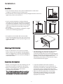
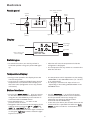
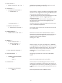
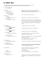
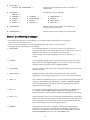
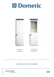
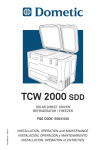
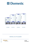
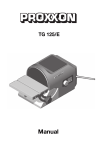
ML 360 CS
ML 380 CS
MP 360 CS
MP 380 CS
820 9505 23 - ed0113
OPERATING INSTRUCTIONS
Dometic S.à r.l.
op der Hei 17
L - 9809 Hosingen, Luxembourg
COPY OF THE ORIGINAL OPERATING INSTRUCTIONS
CONTENTS
page
Important Information
General _____________________________________________________________4
Safety ______________________________________________________________4
Transport ___________________________________________________________4
Environmental Protection _____________________________________________4
Installation
Location ____________________________________________________________5
Cleaning / Disinfection ________________________________________________5
Electrical Connection _________________________________________________5
Electronics
Fascia panel_________________________________________________________6
Display _____________________________________________________________6
Switching on ________________________________________________________6
Temperature Display __________________________________________________6
Button functions _____________________________________________________6
Setting the language __________________________________________________7
The “SETTINGS”-Menu ________________________________________________7
The “EXTRA” - Menu __________________________________________________9
Status- and Warning messages ________________________________________10
Alarm and error messages ____________________________________________11
Use and Operation
Important advise for storage __________________________________________12
Alarm situations ____________________________________________________12
Alarm History _______________________________________________________12
Rechargeable battery ________________________________________________13
External Alarmfunction _______________________________________________13
Safety thermostat ___________________________________________________13
Interior fittings______________________________________________________13
Temperature recorder (optional) _______________________________________14
RS485 Interface _____________________________________________________14
Cleaning ___________________________________________________________14
Fan _______________________________________________________________14
Lighting ___________________________________________________________15
Heater_____________________________________________________________15
Maintenance and repair ______________________________________________15
3
Important Information
General
!
• Keep these operating instructions ready at hand
and leave them with the machine, so that all
users can find out about the functions and safety
regulations.
• Ensure that there is sufficient room around the
unit for air circulation. Please refer to the
installation information regarding this point.
• For translations into foreign languages, the
original German operating instructions are
binding.
• All installation work and adjustments to the unit
must only be carried out by qualified personnel.
Work performed by persons with insufficient
technical knowledge may adversely affect the
performance of the unit or cause physical injury
or damage to the equipment.
• The units must only be used by adults. Do not
allow children to play with the units or touch the
controls.
• All servicing and repairs must only be carried out
by a qualified customer service engineer. Only
genuine spare parts must be used.
• Ensure that the connecting cable is not squeezed
or bent when the unit is being installed or moved.
• Before cleaning or carrying out maintenance
work, always switch the machine off and
disconnect the mains plug. Always pull the plug
and never the cable. If the plug is not accessible,
switch off at the safety device.
• The unit's cooling system contains refrigerant.
Both the unit and the products stored inside can
be severely damaged if this system starts to leak.
Make sure, therefore, that no sharp or pointed
objects come into contact with the cooling
system.
• The sound intensity level produced by the
equipment is lower than 70 dBA (measured in a
distance of 1 meter).
• Refrigerators of the ML- and MP-series are
designed for storage and cooling of preparations
that are subject to cold chain and temperature
sensitive. TThey are not intended for the storage
of blood or blood components.
• The units are not intended to be used for cooling
of foodstuffs.
• Before using the unit, read these operating
instructions carefully, including all the
information on operating safety, use and
maintenance.
Safety
Transport
• The unit must be transported in an upright
position only (maximum inclination 45°).
• Check whether the unit has been delivered
undamaged. If you find that damage has occurred
in transit, immediately contact the delivery
service or relevant sales outlet, submitting the
delivery note or proof of purchase.
• Do not operate a unit that has been damaged in
transit! If you are unsure, contact your sales
outlet and ask them.
Environmental Protection
• Make your contribution to saving the
environment. Bear in mind that orderly and
proper disposal is required. Packaging materials
and devices are always recyclable and should be
taken for recycling.
• Before scrapping an old unit, remove the door so
that children cannot lock themselves inside while
playing.
• Before scrapping the unit, arrange for the lead
accumulator to be removed and disposed of
separately.
• When disposing of the unit, make sure that it
does not get too hot, as combustible gas would
cause the insulating foam to froth up.
4
!
min 70 mm
Location
POWER FAIL
O
min 70 mm
POWER FAIL
ALARM HISTORY
O
I
min 30 cm
Installation
ALARM HISTORY
I
ENTER
ENTER
ALARM TEST
ALARM TEST
POWER FAIL
O
ALARM HISTORY
I
ENTER
ALARM TEST
• The air must be allowed to circulate freely all
round the unit as good air circulation is essential
for trouble-free operation. There must always be
a gap of at least 70mm all round the unit. Upright
units must always be at least 30cm away from
the ceiling.
• Do not locate the unit below a ceiling fan or right
next to air-conditioning equipment.
min
7070
mm
min
mm
POWER FAIL
O
POWER FAIL
ALARM HISTORY
I
O
ALARM HISTORY
I
ENTER
ENTER
ALARM TEST
ALARM TEST
ALARM HISTORY
POWER FAIL
O
min
7070
mm
min
mm
I
ALARM HISTORY
POWER FAIL
O
ENTER
I
ENTER
ALARM TEST
ALARM TEST
min 30 cm
min 30 cm
• The unit must be set up in a dry well-ventilated place. Avoid direct
sunlight or locating it close to a heat source.
• Ensure that the unit is steady and perfectly straight and does not knock
against any of the units next to it.
• Two spacers are included with some models.
These must be attached to the rear of the unit as
shown in the diagram, before positioning the unit
against the wall.
Cleaning / Disinfection
• Clean or disinfect the unit inside and outside
before using it. Use only gentle cleaning agents.
Never use aggressive or caustic cleaning agents,
scouring powder, steel wool, abrasive sponges or
chemical solvents.
• For disinfecting, we recommend all the surface
disinfecting agents commonly used by the
customer, provided they are recommended by the
German Association for Hygiene and Microbiology
(DGHM) or other national organisations. For
disinfecting small areas, we recommend using a
concentrated alcoholic agent.
Electrical Connection
• To prevent problems with other electrical
equipment causing this unit to malfunction, it
should be connected to a separate circuit. Never
connect the unit to a single socket with other
electrical equipment by means of a multi-socket.
• Make sure that the plug of the unit is easily
accessible so that if need be it can be easily
disconnected without having to move other
equipment or furniture.
• Before connecting the unit and switching it on for
the first time, allow it to stand for 30 minutes.
• Before connecting the unit, check whether the
details on the nameplate in the interior
correspond to local values.
• The unit must only be connected to an earthed
socket, secured by protective earth conductor
and adequate fault-current circuit breaker.
5
POWER FAIL
O
I
Electronics
Fascia panel
LEFT, RIGHT,
220VUP, DOWN
buttons
10:32
220V
10:32
red LED
(Alarm)
BACKbutton
Display
220V
10:32
Key switch
MENUbutton
ENTERbutton
green LED
(Power)
Light button
Display
Mute-button
220V
10:32
temperature
status-, warning- and
alarm-messages
DOOR OPEN
BATTERY FAIL
220V
10:32
DOOR OPEN
BATTERY FAIL
220V
10:32
input voltage
current time
220V
10:32
DOOR OPEN
BATTERY FAIL
DOOR OPEN
BATTERY FAIL
door heater
or :
DOOR OPEN
battery
BATTERY
FAIL
Switching on
• To switch the unit on, turn the key switch in
horizontal position. The green power LED lights
up.
• After the self-test, the temperature inside the
refrigerator is displayed.
• The compressor will only switch on a certain time
after the self-test.
Temperature Display
• The temperature unit is dependent on the setting
“TEMP.UNIT” in the SETTINGS menu. (°C - Celsius
or °F -Fahrenheit).
• The display is carried out in steps of 0.1° or 1°
- depending on the setting “RESOLUTION” in the
SETTINGS menu.
• During normal operation the display shows the
internal temperatur
• In the case of a combined fridge/freezer the two
temperatures are indicated on the display one
above the other (refrigerator unit on top, freezer
unit below).
Button functions
• Pressing the MENU-button 3 gives you access
to the menu area. Choose the respective menu
using the UP- and DOWN-keys. The selection is
confirmed with the ENTER-button.
• Press the BACK-key ) to return to the
previous screen or menu.
• Navigation within the menus and changing of the
settings are done using the UP- p , DOWN- q,
LEFT- t und RIGHT u keys.
• In normal display mode the inner light is switched
on using the “light-key”. In Menu-mode the lightkey has no function.
• Use the ENTER-key 8 to confirm the actual
selection. This applies both for menu selection
and for parameter value. The change of a
parameter only becomes effective when
confirmed with the ENTER-key.
• In the case of an alarm, the acoustic alarm can be
switched off for a specified time with the “mute
button”. In Menu-mode the “mute button” is out
of function.
6
220
10:3
Setting the language
3
• The factory language setting of the electronics is
ENGLISH. To convert to another language,
proceed as follows :
press the MENU-key.
q select EXTRA
8
q LANGUAGE
8
q select your language
8
The “SETTINGS”-Menu
• The parameters contained in the “SETTINGS” menu partially intervene in the function of
the appliance. Access to the SETTINGS menu can therefore be protected by a password.
It is recommended to use this protection to limit access to the parameters.
3
q
q
q
q
press the MENU-key
w select “SETTINGS” 8
w USER PASSWORD :
0XXX 8
SET POINT 8
w SET : X.X °C
SET POINT 2 8
w SET 2 : X.X °C
DATE/TIME 8
w SET DATE/TIME 8
w HH:MM
dd MMM yy 8
▼ SELECT 12h/24H 8
w 12h DISPLAY pq 24h DISPLAY 8
ALARMS 8
w SET LOW ALARM 8
w LOW ALARM : X.X °C 8
q
q
q
q
SET HIGH ALARM 8
w HIGH ALARM : X.X °C 8
SET LOW ALARM 2 8
w LOW ALARM 2 : X.X °C 8
SET HIGH ALARM 2 8
w HIGH ALARM 2 : X.X °C 8
REMOTE DOOR ALARM 8
w REMOTE DOOR ALARM
ENABLE : 0 pq 1 8
In the factory setting this password is set to the value
“0000” so that by pressing the 8 - button you get
directly into the SETTINGS menu.
The temperature set point is the set temperature of the
refrigerator. The set point can be altered
between the prescribed limit values in stages of 0.5 K.
Temperature set point in freezer unit for combined
appliances.
Setting current time and date.
Changing between 12-hour and 24-hour display
The lowest admissible internal temperature of the
refirgerator. If the temperature falls below this value a
temperature alarm is triggered.
The highest admissible internal temperature of the
refrigerator. If the temperature exceeds this value a
temperature alarm is triggered.
The lowest admissible internal temperature of the
freezer unit. If the temperature reaches this value a
temperature alarm is triggered.
The highest admissible internal temperature of the
freezer unit. If the temperature reaches this value a
temperature alarm is triggered.
Activation of the remote alarm on opening door
0 = remote alarm off / 1 = remote alarm on.
7
q
q
DOOR HEATER 8
w DOOR HEATER OFF
q
q
REMOTE ACTIVATION 8
w REMOTE OFF pq ON 8
pq
255 8
SERVICE 8
w RESET SERVICE TIME 8
w RESET COUNTER 8
w YES pq NO 8
HIDE SERVICE WARNING 8
USER PASSWORD 8
w
q
ALARM TEST 2 8
COMM. ADDRESS 8
w COMM. ADDR: 0
q
q
ON 8
ALARM TEST 8
w ALARM TEST ACTIVATION 8
w ALARM TEST 8
q
q
pq
CHANGE USER PASSWORD:
0XXX
XXXX 8
CALIBRATION 8
w
CALIBRATION PASSWORD:
0XXX 8
Switching door heater on and off for appliances with
glass doors. (see Chapter “Heater”)
This function is used for simulation a temperature alarm
situation of the refrigerator. Pressing the ENTER-button
will launch the following alarm test cycle:
1. Phased increase of the internal temperature until the
upper alarm limit is reached. Triggering of the
temperature alarm.
2. Phased reduction of the internal temperature until
the lower alarm limit is reached. Triggering of the
temperature alarm.
The same functions as described above for the freezer
unit in combination appliances.
The remote alarm function can be switched on and off
for an alarm test.
With the aid of the built-in RS485 interface several
appliances can be networked with each other. If this is
the case every individual appliance must receive a
separate communication address.
(setting of 0 – 255)
After the expiry of a given operating time a “SERVICE”
message appears on the display to call attention to the
fact that a regular maintenance is due. The counter for
this service time can be put back with this function.
This function is for cancelling the “service”
message.
Changing the password to access the “SETTINGS”
MENU.
Enter the new password twice and confirm.
This function is for calibrating the sensors. As each
setting in the calibration compromises the function of
the appliance, this function is protected by a password
in the factory and must only be used by trained service
staff!
Enter the password to the calibration menu
8
The “EXTRA” - Menu
• The “EXTRA” menu only contains parameters without influence on the function of the
appliance and are therefore accessible for any use without a password.
3
w
press the MENÜ-key
q select “EXTRA” 8
HISTORY 8
w SHOW HISTORY 8
(see chapter “Alarm history” for further details)
Display for alarm situations. With the aid of the UP and
DOWN buttons you can scroll down the list
DELETE HISTORY 8
w DELETE HISTORY:
NO pq YES 8
BUZZER 8
w VOLUME 8
w BUZZER VOLUME pq 8
q MUTE TIME 8
w MUTE TIME : 0 pq 60 8
q
q
q
DISPLAY 8
w BRIGHTNESS 8
w DISPLAY BRIGHTNESS
- ■ + 8
q CONTRAST 8
w DISPLAY CONTRAST 8
- ■ + 8
q POS / NEG 8
w POSITIVE pq NEGATIVE
q
q
q
q
VOLTAGE IND. 8
w LINE VOLTAGE
pq
NONE 8
AMBIENT PROBE 8
w AMBIENT pq NONE 8
ADD.PROBE 8
w
q
q
BACKL. TIMEOUT 8
w TIME OUT: : 0 pq 127 8
Setting the volume of the acoustic alarm signal
On the occurrence of an alarm, the acoustic signal can
be switched off for a given time by activating the ENTER
button. The given time is determined by this parameter.
It can be changed from 0 to 60 minutes in stages of1I
minute.
Setting the parameters for the display
Setting the brightness with the t and u keys.
Setting the contrast with the t and u keys.
8
Changing the display from positive (blue/white) to
negative display (white/blue).
Duration of the display indication on pressing the button
during a power failure.
(100 = approx. 10 Sec, 50 = approx. 5 Sec.)
(see chapter “Alarm situations”)
Shows the input voltage of the appliance on the display.
If an ambient temperature sensor is connected to the
appliance , the temperature measured by this sensor
can be indicated on the display.
Enables the additional display of the temperature
values of one of the following sensors
(if connected):
No value is displayed.
The value of the regulation sensor is displayed.
NONE 8
REGULATION 8
RESOLUTION 8
w RES.: 0.1° pq 1°
YES : deletes the entire history data.
8
Setting the resolution of the temperature display. The
temperature can be displayed with or without decimal
place.
9
q
q
TEMP. UNIT 8
w CELSIUS pq FAHRENHEIT 8
LANGUAGE 8
w ENGLISH 8
q GERMAN 8
q FRENCH 8
q DUTCH 8
q ITALIAN 8
q
DIAGNOSTICS 8
q
PARAMETERS 8
Display of the temperature value in °Celsius or in
°Fahrenheit.
Changing the menu language.
q
q
q
q
SPANISH 8
PORTUGUESE
DANISH 8
SWEDISH 8
q
8
q
q
q
NORWEGIAN 8
FINNISH 8
MALAYSIAN 8
RUSSIAN 8
Display of the current status of the appliance
(only for service purposes).
Display of the current setting of all parameters
Status- and Warning messages
• The electronics generate various status or warning messages depending on the setting or
the condition of the appliance.
• If one or several messages are to be displayed at the same time in one line, these
messages appear alternately on the display.
w
DOOR OPEN
This message appears as soon as the door of the appliance is
opened. If the door is not closed again after a preset time, an alarm is
triggered. This alarm is not entered in the history list.
The message or the alarm disappears as soon as the door is
closed.
w
HISTORY
This message indicates that a new entry has been made in the alarm
history list. The message disappears as soon as the history has been
displayed once with the function “SHOW HISTORY”.
w
ALARM TEST
Appears during an alarm test. The message disappears as soon as the
test has finished.
w
ALARM TEST 2
Appears during an alarm test of the freezer unit with combined
appliances. The message disappears as soon as the test has finished.
w
AMB ..°C
If an ambient temperature sensor is connected to the appliance and the
display in the EXTRA menu activated (3 - EXTRA - AMBIENT PROBE),
this message appears followed by the currently measured ambient
temperature in the display.
w
REG ..°C
If the display of the regulating sensor is activated in the EXTRA menu
(3 - EXTRA - ADD. PROBE - REGULATION) this message appears
followed by the currently measured control temperature in the display.
w
REG 2 ..°C
With the display of the control temperature activated with combination
appliances, this message appears followed by the currently measured
control temperature of the freezer unit in the display alternately with
the control temperature of the refrigerating unit.
w
SERVICE
If the appliance has been running for a preset time this message
appears on the display to indicate that a cleaning or maintenance
procedure is required. The message can be cancelled with the “HIDE
SERVICE WARNING” function in the SETTINGS menu.
10
w
HIGH AMBIENT TEMP.
If an ambient temperature sensor is connected to the appliance and if
this value rises above a given value this message appears on the
display. The appliance will however function normally. The maximum
value stored in the electronics depends on the temperature class of the
appliance in question and cannot be changed.
w
LOW AMBIENT TEMP.
analogous to “HIGH AMBIENT TEMP.” however with minimum value.
Alarm and error messages
• The following alarm messages can be generated by the electronics. Refer to
the chapter “Alarm situations” for further information
w
DOOR OPEN
see status-message “DOOR OPEN”
w
HIGH ALARM
This alarm message appears as soon as the internal temperature
exceeds the given upper alarm limit. A temperature warn alarm is
stored in the Alarm History. The alarm message disappears as soon as
the temperature reaches the upper alarm limit again.
w
LOW ALARM
This alarm message appears as soon as the internal temperature falls
below the given lower alarm limit. A temperature cold alarm is stored in
the Alarm History. The alarm message disappears as soon as the
temperature reaches the lower alarm limit again.
w
HIGH ALARM 2
as described above but for the freezer unit in combination
appliance.
w
LOW ALARM 2
as described above but for the freezer unit in combination
appliance.
w
POWERFAIL
This message appears if the power supply is interrupted with the
appliance switched on.
A power failure alarm is stored in the alarm history. The alarm message
disappears as soon as the power supply is restored.
• If one of the following error messages appears on the display, a fault or a
malfunction has occurred and the affected component must be repaired or
replaced by the service staff.
w
BAT.1 LOW/FAIL
w
BAT.2 LOW/FAIL
w
SENS. REG. FAIL
Failure of the control sensor. The appliance continues to run in
“FAILSAFE” mode.
w
SENS. REG-FR. FAIL
Failure of the control sensor of the freezer unit in combination
appliances. The appliance continues to run in “FAILSAFE” mode
w
SENS. DIS. FAIL
Failure of the display sensor. In this case the display function is taken
over by the control sensor.
w
SENS. DIS-2 FAIL
Failure of the display sensor of the freezer unit in combination
appliances. In this case the display function is taken over by the control
sensor of the freezer unit.
w
SENS. AMB. FAIL
Failure of the ambient temperature sensor.
This message appears if the internal main battery is faulty or flat. At
the same time the battery symbol also appears on the display.
This message appears if the optional additional battery is faulty or flat.
At the same time the battery symbol also appears on the display.
11
w
E1 / CFGERROR
Configuration fault: Fault in the parameter setting. The appliance does
not start.
w
E2
Electronics fault. The function of the appliance is stopped.
w
COM ERROR
No communication between interface and mainboard. The function of
the appliance is stopped.
w
FAILSAFE MODE
Serious fault, however the appliance continues to run in "FAILSAFE”
mode. i.e. the compressor switches on and off according to the set
rhythm.
Use and Operation
Important advise for storage
• Make sure that the loaded goods do not tilt to the
backside.
• Make sure that the loading does not touch the
reference bottle of the display sensor.
• Do not overload the unit.
• The goods should only be stored in the provided
drawers and/or racks.
• The loading must never obstruct the air-inletopenings inside the unit.
Alarm situations
After a given time (setting: EXTRA - DISPLAY BACKL. TIMEOUT ) the display switches off again.
The acoustic alarm can be suppressed for a set
time by pressing the ENTER button. During a
powerfail phase no parameters can be changed.
• If the internal temperature rises above the upper
limit during a powerfail phase a temperature
alarm is triggered and entered into the History
list. In the case of a door alarm the red LED lights
up and an acoustic signal sounds. In addition the
corresponding alarm message appears on the
display
• On the occurrence of an alarm situation attempts
must be made to find out the reason for the
alarm and remove it as quickly as possible. If that
is not successful the necessary measures must
immediately be taken so that the stored goods do
not sustain any damage.
• At a temperature alarm the red LED alarm lights
up and an acoustic signal sounds. In addition the
corresponding alarm message appears on the
display.
• In the case of a powerfail alarm the green power
LED and the red LED alarm flash and an acoustic
signal sounds. The display is switched off but be
temporarly switched on again by pressing any
key.
Alarm History
• The alarm history list can be accessed via the
“SHOW HISTORY” function in the EXTRA menu.
Within the list you navigate by means of the UP
and DOWN buttons. The first and last entry in the
list are marked “BEGIN OF LIST” and “END OF
LIST”
• The alarm history list contains all relevant data
on temperature and powerfail events. The list
contains up to 20 alarm situations.
• The status message “HISTORY” indicates that
new entries have been made in the list.
• The following information is stored in the Alarm History :
w
Temperature alarm :
ALARM :
type of alarm (HIGH ALARM or LOW ALARM)
START :
Start date and time of alarm situation
END :
End date and time of alarm situation
AVG :
Average temperature on the display sensor during the alarm situations.
MAX / MIN :
Maximum or minimum temperature value on the display sensor during the
alarm situation (depending on the type of temperature alarm)
12
w
Powerfail alarm :
ALARM :
START :
END :
AVG :
POWERFAIL
Start date and time of alarm situation
End date and time of alarm situation
Average temperature on the display sensor during the alarm situations
• To delete the alarm history, select the function “DELETE HISTORY” from the EXTRA menu.
Rechargeable battery
• The monitoring functions of the electronics
during an interruption of the power supply for at
least 48 hours are maintained by an integrated
rechargeable battery.
• This battery is automatically charged when the
appliance is connected.
• If the capacity of the battery is no longer
sufficient to take over the control function, the
error message “BAT.1 LOW/FAIL” appears on the
display.
• At the first starting up it may happen that the
message „BAT.1 LOW/FAIL” appears. The message
will disappear as soon as the battery is charged.
• The battery should be pre-emptively replaced
every 2 years. This replacement must only be
carried out by a recognised service technician.
Before dismantling the battery the appliance
must be switched off and the plug pulled out.
• The battery is a lead-acid storage battery that
must be disposed of separately in the case of a
fault.
External Alarmfunction
• There are two terminals with three floating
contacts on the back of the unit that can be used
to trigger an additional external alarm (visual or
audible).
• The upper contacts correspond to temperatureand door-alarm, the lower contacts correspond to
a powerfail-alarm.
• Pressing the ENTER-key in an alarm situation
only switches off the internal audible alarm. The
key does not interfere with the external alarm.
The external alarm signal is only switched off
once the cause of the alarm has been eliminated.
• A voltage of between 12V DC and a maximum of
250V AC can be connected at the contacts. The
maximum load must not exceed 8A. The minimum
power rating is 100mA / 5V.
TEMPERATURE-ALARM
DOOR-ALARM
POWERFAIL-ALARM
Resting state
Resting state
Alarm
Alarm
Safety thermostat
• All units are fitted with a safety thermostat. This
thermostat switches off the compressor as soon
as the inside temperature falls below +2°C, to
prevent the goods being harmed by freezing.
Interior fittings
• Depending on the model series, heightadjustable drawers or racks are included as
standard fittings.
• The load must be evenly distributed over the
drawers or racks.
• Pull out the drawers using the handles only.
• To remove the drawers (e.g. to clean them), pull
the draw out to the stop and then lift.
• The appliances are designed in such a way that
they have optimal function with the original
fittings. If interior fittings from other suppliers
are to be used, this must be definitely agreed
with the manufacturer.
13
Temperature recorder (optional)
• The recorder is used to record the temperature
response over a certain period. This period can
either be set to 7 days (preset) or 24 hours, as
required. To change the setting, proceed as
follows: raise the lever with the recording stylus
and take the lock nut off the recorder axis. You
can now remove the recorder disk. Now pull the
recorder axis to remove the assembly from the
housing. The switch with which to set the
required time period is located on the side of the
assembly.
• The disks for the two time periods are different.
Make sure that you insert the correct disk.
• The clockwork for the recorder is powered by a
1.5V AA battery. This is located on the underside
of the recorder assembly.
!
• To replace the stylus, take the old stylus out of
the stylus retainer and push the new one into the
guides until it stops. Be careful not to touch the
stylus with your fingers.
• When re-assembling, make sure that the lock nut
is sited correctly.
RS485 Interface
• The unit is equiped with an RS485 interface. You
can use this interface to connect the unit to a PC
or to network it to other refrigerating equipment.
• For information about connection options and
software, contact your local service centre.
Cleaning
• The refrigerator should be cleaned and if
necessary disinfected before you use it for the
first time and then at regular intervals thereafter.
• Only use gentle cleaning agents. Never use
aggressive or caustic cleaning agents, scouring
powder, steel wool, abrasive sponges or chemical
solvents. When cleaning, make sure that no fluids
of any kind run into the ventilation housing.
• Before restarting the unit after cleaning, the
interior must be thoroughly dried.
Fan
• When units are fitted with internal ventilation, it
is vital that the interior fan is always in working
order.
• To prevent warm outside air being sucked in
unnecessarily when the door is open, the fan
switches off when the door is opened.
• The airflow to the fan must never be impeded.
The ventilation slots must therefore never be
blocked or covered.
14
Lighting
• The lighting consists of a long-lasting and
maintenance-free
LED lamp.
220V
10:32
• If the LED should fail, it must be completely
replaced. This change may only be done by
customer service or by a qualified electrical
technician.
• The devices are equipped with an optional
interior lighting.
• The interior light is turned on with every door
opening, but it can also be switched on or off with
the appropriate button on the electronics.
Heater
220V
• Models with glass door are equipped with a door
heater.
• If the door mists over, this heater can be switched
on or off via the function “DOOR HEATER” in the
SETTINGS menu.
220V
10:32
• When the10:32
heater is switched on
the heater
symbol
appears in the display.
DOOR OPEN
BATTERY FAIL
DOOR OPEN
BATTERY FAIL
Maintenance and repair
Important :
Before cleaning or carrying out maintenance
work, switch the device off completely and pull
out the mains plug.
• All service work and repairs may only be carried
out by qualified Customer Service technicians.
Only original spare parts may be used.
• Dust must be removed regularly from the
condenser/liquefier in the machine compartment
with the aid of a handbrush or a vacuum cleaner.
This cleaning interval is specified by the factory
and is shown by a “SERVICE” message on the
display.
• The battery should be replaced every 2 years as a
preventative measure.
• A defective connection cable may not be
repaired. It must be replaced by customer service
or by a qualified electrical technician.
15