1
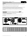
Operating instructions Installation / Operation PTFE-seated butterfly valve series K Introduction The following information and instructions are important for perfect installation and safe operation of the valve. Prior to installation and initial use of the valve, the qualified staff in charge of installing and operating the valve has to be instructed according to this information. Proper use The PTFE-seated butterfly valve series K may only be used to stop, throttle and control media flows within the permissible pressure/temperature limits. The suitability of the product-related parts used and their chemical resistance properties have to be clarified before start-up of the plant. The usual flow rate must not be exceeded. Vibrations, water hammers and cavitation as well as abrasive components result in damage of the valve and affect its service life. Valves must not be used to support the pipeline nor as a step-up. This includes the different kinds of operation like hand levers, gear operators, actuators, feedback and control systems. When using a hand lever, handwheel and manual emergency operation, take care that there is enough space for a proper operation. Earthing the valve If the butterfly valve is supplied with anti-static device and used in potentially explosive zones, the earthing strap supplied with the valve must be connected effectively at site with the potential compensation cable before the valve is put into operation. \K-PTFE-Ausgekleidet-Einbauanleitung (GB).doc (GR) 13.07.2010 1/4 Operating instructions Installation / Operation PTFE-seated butterfly valve series K Transport and storage The valve must be transported and stored dry and clean. In humid rooms, a drying material or heating must be used to avoid condensation. During transport and intermediate storage the butterfly valve should not be outside a temperature range of -15°C and +30°C. The transport packaging protects the valve against soiling and damage. Impact and vibrations must be avoided. The outer paintwork (coating) must remain undamaged, otherwise the faulty spots must be repaired immediately. The factory-adjusted basic setting (position of the disc at delivery) must not be changed. Conditions for mounting the valve The PTFE-seated butterfly valve series K is installed between pipeline flanges acc. to DIN2501 or ANSI B16.5. The pipeline must not have any axial or angular offset, since otherwise the disc could be damaged and the PTFE-seat can become deformed, which is not permitted. Due to the PTFE-seat design the butterfly valve is "self-sealing" to the flanges and does not require additional flange gaskets. Pre-condition: The flange sealing surfaces have been checked to make sure that they have a smooth surface structure. Residues (welding beads) must be removed. No cross marks may be visible. Use PTFE flange gaskets with metal back-up ring only in exceptional case. Make sure that the PTFE flange gaskets cover the whole sealing surface of the flange connection. The "clearance" of the mating flanges - including inner coatinghas to be sufficient to allow the disc to be fully opened without touching (ØDi ØL + 6 mm). This must be checked before the valve is installed and compared with the space necessary for the valve according to the table. DN 50 65 80 100 125 150 200 250 300 350 400 500 D 43 46 46 52 56 56 60 68 78 78 102 127 ØL 33 48 64 91 117 137 190 240 290 330 377 475 X 6 10 17 27 37 46 70 91 111 131 144 182 Transport packaging Transport packaging protects the interior of the valve from soiling and damage. Do not remove the packaging until the valve is going to be installed. Installation position Basically the butterfly valve series K can be installed in any position. The recommended position, however, is with the shaft being horizontal. The lower disc edge should open in flow direction. K-PTFE-Ausgekleidet-Einbauanleitung (GB).doc (GR) 13.07.2010 2/4 Operating instructions Installation / Operation PTFE-seated butterfly valve series K Installation The PTFE-seated butterfly valve series K has to be switched to the fully closed position or a slightly angled position. The position of the disc must be within the face-to-face dimension of the valve. Spread the mating flanges and insert the valve carefully between the flanges. If the pipeline is to be welded at site, temporary fitting blocks should be installed instead of the butterfly valve, since flying sparks and welding residues can damage the valve seat due to high temperatures. Never leave the butterfly valve installed when welding of the pipeline/flanges has to be completed. Center the butterfly valve using the flange screws. The outside diameter of the valve body is used for full centering! Remove the flange-spreaders and tighten the flange screws slightly and evenly crosswise with the disc fully closed. During this procedure, check that the valve is centered between the mating flanges. Open and close the valve several times and cross-tighten the flange screws once again with the disc in closed position. (Tightening torque: please refer to below table). Check that the disc has adequate clearance. When installing the lug type butterfly valve as end-in-line valve, the free port must be secured by a blind flange. Tightening torque for flange screws DN 40 50 65 80 100 125 150 200 250 300 350 400 500 NPS 1 ½ 2 2 ½ 3 4 5 6 8 10 12 14 16 20 Tightening torque [Nm] 30 30 35 35 40 55 80 100 100 120 130 170 170 K-PTFE-Ausgekleidet-Einbauanleitung (GB).doc (GR) 13.07.2010 3/4 Operating instructions Installation / Operation PTFE-seated butterfly valve series K Mounting of actuators It must be ensured that the actuator is centred on the valve shaft. The weight of a mounted actuator must not place a one-sided load on the shaft of the valve: if necessary actuators must be supported without fixing. External loads must not be applied to actuators, this can damage or destroy the valve. Initial operation The butterfly valve has been tested for leakage using air or water. Residues of the test medium may still be on the contact surfaces of the valve. Possible reactions with the operating medium must be observed. Prior to initial operation, the pipeline must be flushed effectively with the valve fully opened to eliminate soiling and to avoid damage to the sealing surfaces. The valve must not be switched during the flushing process. During a system pressure test the following pressures must not be exceeded: 1,5 x PN with disc in open position 1,1 x PN with disc in closed position Impermissible operation Never operate the butterfly valve without actuating devices and/or locking of the shaft. Do not operate the valve in the cavitation area. Do not exceed the pressure/temperature range. Avoid all foreign particles on the sealing surfaces. Removing the valve Before removing the butterfly valve make sure that the pipe section is depressurised and evacuated. In case of toxic, caustic and other outgasing media the pipe section must also be ventilated. Safety classification is the responsibility of the system operator. The butterfly valve is removed by loosening the flange screws and sufficient spreading of the mating flanges. The valve disc must be closed at an angle within the face-to-face dimension of the valve to prevent damage to the disc. Actuators either have to be dismounted before the valve is removed or they have to be secured against unauthorized or unintentional operation. Disposal / repair of the valve After having removed the valve it has to be disassembled and cleaned to prevent injuries caused by residues of the medium. If the valve is returned to the manufacturer, a safety data sheet relating to the media must be included. Subject to modifications without notice. Edition: 2010-07-13 K-PTFE-Ausgekleidet-Einbauanleitung (GB).doc (GR) 13.07.2010 4/4 Operating instructions Maintenance / Mounting PTFE-seated butterfly valve series K Maintenance The valves do not require any special maintenance. Disassembly Valves with hand lever: Loosen the lateral screw joint of the hand lever and pull the hand lever off the valve stem (3). If only the seat (2) or the disc (3) have to be replaced, the throttle plate can be left mounted. Remove the throttle plate by loosening the screws to replace the bearing (6). Valves with actuator: Loosen the fastening screws between the MULTITOP mounting plate (29) and the actuator or between the valve and the bracket and remove the actuator to replace the bearing (6). Remove the MULTITOP mounting plate (29) from the valve by loosening the fastening screws (31) and the clamping sleeves (30). If only the seat (2) or the disc (3) has to be replaced, the actuator may remain on the valve. Turn the disc to "OPEN" position. Loosen and remove the two body screws (8). Pull off the lower part of the body (1b). The lower part or the body can easily be pulled off by pressing screw drivers into the body split. Pull the disc (3) with the seat (2) out of the upper part of the body (1a). If the disc (3) is to be reused, it should be heated together with the seat (2) to at least 100 °C (better 150 °C). This can be achieved in a water bath (boiling, 100°C) or better in a heating furnace. After warming the disc / seat unit, the seat ring becomes pliable. Deform the seat into an oval and pull it first over the lower stem part of the disc. Thereafter, pull the seat upwards. Allocate the thrust pads (5), disc spring washers or compression springs (7) and the adjusting washers (if present) to the upper and lower body part (1a/1b) in the same way as they were found. Comment: Four disc spring washers are used per body half for DN 50 to DN 150 and DN 500. One compression spring is used per body half for DN 200 to DN 400. Check all part for flawless condition and renew them, if required. Only use original GEFA spare parts. Assembly Thoroughly clean all parts and check them for wear. Parts that show wear or corrosion must be replaced to ensure operational safety in future. Equip the thrust pads (5) with a new FPM O-ring (10), if required. Allocate the disc spring washers or compression springs (7) to the body halves (exchange them, when they are corroded). Insert the adjusting washers into the body parts in the original pattern. Check the disc (3) and slide a new FEP O-ring (9) over both stem parts and into the groove of the disc. Heat the seat (2) in the form it is delivered as spare part with inlayed elastomer (4) in an heating furnace to 150°C (maximum 15 minutes) or in boiling water to 100°C. Pull the hot seat (2) over the long stem part of the prepared disc (3). Clamp the flat of the disc with a vice (use aluminium jaws). Pull the seat over the short stem part. For this purpose, the seat is distorted into an oval. Place the disc spring washers or compression spring (7) and the thrust pad (5) into the upper part of the body (1a). Insert the complete disc (3) / seat (2) unit into the upper part of the body (1a). Place the disc spring washers or compression spring (7) and the thrust pad (5) into the lower part of the body (1b). Assemble the upper and lower part of the body (1a/1b) and fasten them with the body screws (8). Each body half has a small moulded cam at the body split that shows the correct position of the body halves in relation to each other. Insert the bearing with the O-rings (6) into the upper body part (1a) if the bearing has to be replaced. After the assembly the disc has to be switched for several times (at least 4x) by 180°. Check the seat and the stem tightness. Test pressure 1.1 times nominal pressure. Valves with hand lever: Loosely attach the throttle plate with the screws to the top flange. Slide the hand lever onto the stem and position the throttle plate. Tighten the fastening screws of the throttle plate and attach the lever with the lateral screw joint. Valves with actuator: Attach the whole actuator unit, align it and fasten it with screws. Mounting of the MULTITOP mounting plate. Position the mounting plate (29) on the body. Insert the spring dowel sleeves (30) through the mounting plate into the body. The slot in the spring dowel sleeve must point in the force direction (see arrow in the assembly drawing) to achieve a rigid connection. Do not insert the mounting plate without using spring dowel sleeves, as the transverse forces cannot be absorbed by the screws. Insert the cylinder screws (31) and tighten them. Slide a square adapter (32) onto the stem, if required. Prevent the square adapter from sliding down the stem by using the attached washer (33), if required. \K-PTFE-Ausgekleidet-Wartungsanleitung (GB) (GR) 10.12.2014 1/2 Operating instructions Maintenance / Mounting PTFE-seated butterfly valve series K 1a 1b 2 3 4 5 Upper part of the body Lower part of the body Seat Disc Elastomer Thrust pad 6 7 8 9 10 29 Subject to modifications without notice K-PTFE-Ausgekleidet-Wartungsanleitung (GB) (GR) 10.12.2014 Bearing with O-ring Disc spring washer/compression spring Body screw O-ring O-ring MULTITOP mounting plate 30 31 32 33 34 35 Spring dowel sleeve Cylinder screw Square adapter Retaining washer Washer Hexagonal nut Edition: 2014-12-10 2/2