1
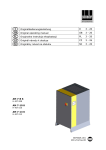
Birox 80, Birox 90, Birox 100,
Birox 150, Birox 200
Mehrzweckpumpe
Multi-purpose pump
Pompa uniwersalna
Pompă universală
Montage- und Betriebsanleitung
Installation and Operating Instructions
Instrukcja montażu i eksploatacjiInstallation and
Instrucţiuni de montaj şi exploatare
Mehr als Pumpen
2
Konformitäts-Erklärung
DE
Declaration of Conformity
EN
Wir Biral AG erklären in alleiniger Verantwortung,
dass die Produkte
We Biral AG declare under our sole responsibility
that the products
Birox
Birox
auf die sich diese Erklärung bezieht, mit folgenden
Richtlinien des Rates zur Angleichung
der Rechtsvorschriften der EG Mitgliedstaaten
übereinstimmen:
– Maschinen (2006/42/EG)
Norm: EN 12100-1
– Elektrische Betriebsmittel zur Verwendung
innerhalb bestimmter Spannungsgrenzen
(2006/95/EG)
Normen: EN 60335-1:2002
– Elektromagnetische Verträglichkeit (2004/108/EG)
Normen: EN 61000-6-1
Deklaracja zgodności
PL
to which this declaration relates, are in conformity
with the Council Directives on the approximation
of the laws of the EC Member States relating to:
– Machinery (2006/42/EC)
Standard: EN12100-1
– Electrical equipment designed for use
within certain voltage limits (2006/95/EC)
Standards: EN 60335-1:2002
– Electromagnetic compatibility (2004/108/EC)
Standards: EN 61000-6-1
Declaraţie de conformitate
RO
My - firma Biral - oświadczamy na własną
odpowiedzialność, że wyroby
Noi, Biral AG, declarăm pe proprie răspundere
că produsele
Birox
Birox
do których odnosi się niniejsza deklaracja,
są zgodne z dyrektywami Rady w sprawie
zbliżenia
ustawodawstw Państw Członkowskich:
– Dyrektywa maszynowa UE (2006/42/EG)
Norma: EN 12100-1
– Elektryczne środki pracy do stosowania
w określonych granicach napięcia (2006/95/EG)
Normy: EN 60335-1:2002
– Kompatybilność elektromagnetyczna
(2004/108/EG)
Normy: EN 61000-6 -1
la care se referă această declaraţie corespund
cu următoarele Directive ale Consiliului
pentru armonizarea prevederilor legale
ale statelor membre CE:
– Utilaje (2006/42/CE)
Norma: EN 12100-1
– Echipamente electrice pentru utilizarea
în cadrul anumitor limite de tensiune (2006/95/CE)
Normele: EN 60335-1:2002
– Compatibilitate electromagnetică (2004/108/CE)
Normele: EN 61000-6-1
Authorized representative for the completion
of the technical documentation:
Productmanager Watersupply
Südstrasse 10, CH-3110 Münsingen, Schweiz
Münsingen, 1st September 2010
Biral AG, Südstrasse 10, CH-3110 Münsingen
Phone +41 (0) 31 720 90 00, Fax +41 (0) 31 720 94 42
Mail: [email protected], www.biral.ch
Peter Gyger
Technical Director
3
deutsch
1. Sicherheitshinweise
1.1 Allgemeines
Diese Montage- und Betriebsanleitung enthält grundlegende
Hinweise, die bei Aufstellung, Betrieb und Wartung zu beachten
sind. Sie ist daher unbedingt vor Montage und Inbetriebnahme
vom Monteur sowie dem zuständigen Fachpersonal/Betreiber zu
lesen. Sie muss ständig am Einsatzort der Anlage verfügbar sein.
Es sind nicht nur die unter diesem Abschnitt «Sicherheitshinweise»
aufgeführten, allgemeinen Sicherheitshinweise zu beachten,
sondern auch die unter den anderen Abschnitten eingefügten,
speziellen Sicherheitshinweise.
1.2 Kennzeichnung von Hinweisen
Die in dieser Montage- und Betriebsanleitung
enthaltenen Sicherheitshinweise, die bei Nichtbeachtung Gefährdungen für Personen hervorrufen können, sind mit allgemeinem Gefahrensymbol «Sicherheitszeichen nach DIN 4844-W9»
besonders gekennzeichnet.
Dieses Symbol steht für Warnung vor
gefährlicher elektrischer Spannung.
«Sicherheitszeichen nach DIN 4844-W8».
Achtung
Dieses Symbol finden Sie bei Sicherheitshinweisen, deren Nichtbeachtung Gefahren
für die Maschine und deren Funktionen
hervorrufen kann.
Direkt an der Anlage angebrachte Hinweise wie zum Beispiel
– Drehrichtungspfeil
– Kennzeichen für Fluidanschlüsse
müssen unbedingt beachtet und in vollständig lesbarem Zustand
gehalten werden.
1.3 Personalqualifikation und -schulung
Das Personal für Montage, Bedienung, Wartung und Inspektion
muss die entsprechende Qualifikation für diese Arbeiten
aufweisen. Verantwortungsbereich, Zuständigkeit und die
Überwachung des Personals müssen durch den Betreiber genau
geregelt sein.
1.4 Gefahren bei Nichtbeachtung der Sicherheitshinweise
Die Nichtbeachtung der Sicherheitshinweise kann sowohl eine
Gefährdung für Personen als auch für die Umwelt und Anlage
zur Folge haben. Die Nichtbeachtung der Sicherheitshinweise
kann zum Verlust jeglicher Schadenersatzansprüche führen.
4
deutsch
Im einzelnen kann Nichtbeachtung beispielsweise folgende
Gefährdungen nach sich ziehen:
– Versagen wichtiger Funktionen in der Anlage
– Versagen vorgeschriebener Methoden
zur Wartung und Instandhaltung
– Gefährdung von Personen durch elektrische
und mechanische Einwirkungen
1.5 Sicherheitsbewusstes Arbeiten
Die in dieser Montage- und Betriebsanleitung aufgeführten
Sicherheitshinweise, die bestehenden nationalen Vorschriften
zur Unfallverhütung sowie eventuelle interne Arbeits-, Betriebsund Sicherheitsvorschriften des Betreibers, sind zu beachten.
1.6 Sicherheitshinweise für den Betreiber/Bediener
Gefährdungen durch elektrische Energie sind auszuschliessen
(Einzelheiten hierzu siehe zum Beispiel in den Vorschriften
des NIN (CENELEC) und der örtlichen Energieversorgungsunternehmen).
1.7 Sicherheitshinweise für Montage-, Wartungsund Inspektionsarbeiten
Der Betreiber hat dafür zu sorgen, dass alle Montage-, Wartungsund Inspektionsarbeiten von autorisiertem und qualifiziertem
Fachpersonal ausgeführt werden, das sich durch eingehendes
Studium der Montage- und Betriebsanleitung ausreichend
informiert hat.
Grundsätzlich sind Arbeiten an der Anlage nur im Stillstand
durchzuführen.
Unmittelbar nach Abschluss der Arbeiten müssen alle Sicherheitsund Schutzeinrichtungen wieder angebracht bzw. in Funktion
gesetzt werden.
Vor der Wiederinbetriebnahme sind die im Abschnitt
«Elektrischer Anschluss» aufgeführten Punkte zu beachten.
1.8 Eigenmächtiger Umbau und Ersatzteilherstellung
Umbau oder Veränderungen an Pumpen sind nur nach Absprache
mit dem Hersteller zulässig. Originalersatzteile und vom Hersteller
autorisiertes Zubehör dienen der Sicherheit.
Die Verwendung anderer Teile kann die Haftung für die daraus
entstehenden Folgen aufheben.
1.9 Unzulässige Betriebsweisen
Die Betriebssicherheit der gelieferten Pumpen ist nur bei
bestimmungsgemässer Verwendung entsprechend Abschnitt
«Verwendungszweck» der Montage- und Betriebsanleitung
gewährleistet. Die in den technischen Daten angegebenen
Grenzwerte dürfen auf keinen Fall überschritten werden.
2. Transport / Lagerung
Die Pumpen werden vom Werk in einer zweckmässigen Verpackung
geliefert.
5
deutsch
3. Verwendungszweck
Die Mehrzweckpumpe aus hochwertigem rostfreiem Edelstahl,
für transportablen und stationären Einsatz, mit eingebauter
Niveausteuerung. Bei Dauerbetrieb muss die Pumpe voll mit
Förderflüssigkeit überdeckt sein.
3.1 Förderflüssigkeiten
Zur Förderung von leicht verschmutztem Wasser mit Festbestandteilen
(siehe technische Daten) ohne aggressive Beimengungen.
Einsatzgebiete
– Kellerentwässerung
– Waschküchenentwässerung
– Schacht- und Grubenentleerung
– Auspumpen von Behältern
– Grundwasserabsenkung
Die Pumpe eignet sich nicht für die Förderung von:
– Fäkalien
– Medien mit langfaserigen Bestandteilen
– Brennbaren oder explosiven Medien
(Öl, Benzin, Farbverdünner u.ä.)
– Aggressive Medien (z. B. Kondensat,
Rückspülwasser von Enthärtungsanlagen)*
– Benutzung der Pumpe in Schwimmbecken
nicht zulässig gemäss EN 60 335-2-41
– Trockenlauf nicht gestattet
– Für den Einsatz in explosionsgefährdeten
Umgebungen (ATEX)
* Hinweis: Schutzanode-Set verwenden
4. Installation
4.1 Transportabler Betrieb
Pumpe immer am Handgriff, nie am Kabel,
Druckschlauch oder Niveauschalter
tragen oder aufhängen.
– Zum Absenken in einen Schacht oder eine Grube, immer ein Seil
oder eine Kette am Handgriff befestigen
– Druckleitung: flexible, knickfreie Schlauchleitung verwenden
(Biral-Zubehör)
4.2 Stationärer Betrieb
– Pumpe auf festen und stabilen Untergrund stellen
– Druckleitung: Die feste Rohrleitung (Kunststoffleitung)
nur von Hand in den Druckstutzen einschrauben.
Rohrleitung spannungsfrei montieren
– Bei Rücklauf- oder Rückstaugefahr Rückschlagklappe
und Absperrschieber in die Druckleitung einbauen
(Hinweis:
wenn möglich ausserhalb des Sammelschachtes montieren)
– Der Niveauschalter muss sich frei bewegen können
6
deutsch
4.3 Elektrischer Anschluss Birox 80 / 90 / 100 / 150 (1× 230 V)
Für Ihre Sicherheit
– Netzspannung gemäss den Angaben auf dem Typenschild
kontrollieren
– Die Pumpe ist mit dem Stecker an eine vorschriftsmässig
installierte fehlerstromgeschützte Steckdose anzuschliessen
Betrieb der Pumpe darf nur über
Fehlerstromschutzschalter erfolgen
(max. Nennauslösestromstärke
der Fehlerstromschutzschalter FI 30 mA,
DIN VDE 0100T739
SEV-Vorschrift, NIN (CENELEC)
– Bei Blockieren des Laufrades wird die Pumpe durch den eingebauten
thermischen Motorschutz ausgeschaltet. Eine Wiedereinschaltung
der Pumpe erfolgt nach Abkühlen des Motors automatisch
– Vor jeder Arbeit an der Pumpe Netzspannung ausschalten
(Stecker ziehen).
4.4 Elektrischer Anschluss Birox 100 / 150 / 200 (3 × 400 V)
Der elektrische Anschluss muss von einem
Fachmann in Übereinstimmung mit den
örtlichen Vorschriften vorgenommen werden.
Achten Sie darauf, dass die auf dem Typenschild
angegebenen elektrischen Daten, mit der
vorhandenen Stromversorgung übereinstimmen.
Anschluss ans Stromversorgungsnetz
Die Pumpe muss gemäss dem folgenden Schema
ans Stromversorgungsnetz angeschlossen werden.
Motorschutzschalter gemäss der
Stromaufnahme des Pumpenmotors
(siehe Typenschild am Pumpenmotor) einstellen.
Spannung 3 × 400 V
PE
U1
V1
W1
gelb/grün
(L1)
(L2)
(L3)
7
deutsch
Zum Prüfen der Drehrichtung das Pumpen-Aggregat an einem Seil
oder einer Kette aufhängen und den Motor kurz laufen lassen
(einschalten und wieder ausschalten). Wenn die Drehrichtung des
Laufrades stimmt, schlägt die Pumpe im Gegenuhrzeigersinn zurück.
Die Drehrichtung kann durch Umklemmen von zwei Phasen geändert
werden.
Drehrichtung
Pumpe
Rückschlag
Pumpe
Pumpe schwenkt aus!
5. Inbetriebnahme
Betrieb der Pumpe darf nur über
Fehlerstromschutzschalter erfolgen
(max. Nennauslösestromstärke
der Fehlerstromschutzschalter 30 mA,
DIN VDE 0100T739
SEV-Vorschrift, NIN (CENELEC)
Der an der Pumpe angebaute Niveauschalter ermöglicht eine
wasserstandsabhängige automatische Ein- bzw. Ausschaltung
der Pumpe.
Achtung
Der Niveauschalter
muss sich frei bewegen können.
Die Pumpe ist nach dem Eintauchen in das Fördermedium
und dem Anschliessen an eine Steckdose sofort betriebsbereit.
Längerer Trockenlauf oder Schlürfbetrieb
ist nicht zulässig.
8
deutsch
Wenn die Pumpe (Variante A) nicht fördert,
weil Luft in der Druckleitung ist, muss ein Loch 3 mm
(siehe Bild 20 9940) vorsichtig gebohrt werden.
Bei der Variante B ist das Lüftungsloch bereits unter
der Abdeckung vorhanden.
(gilt für Birox 90, Birox 100, Birox 150, Birox 200)
Vor jeder Arbeit an der Pumpe Netzspannung
ausschalten (Stecker ziehen).
Markierung
Entlüftungsloch bohren
Variante A: ohne Entlüftungsloch
Bei Ausführung
mit Abdeckung
ist das Lüftungsloch
bereits vorhanden
Variante B: mit Entlüftungsloch
6. Wartung
Die Pumpe ist wartungsfrei.
– Bei transportabler Verwendung die Pumpe nach jedem Einsatz
durch Fördern von Frischwasser reinigen, um Schmutzablagerungen
und Verkrustungen zu vermeiden.
– Bei stationärer Verwendung von Zeit zu Zeit die Funktion
des Niveauschalters überprüfen.
deutsch
9
7. Abmessungen
Birox 80
EIN
ENCL.
ON
Birox 90
EIN
ENCL.
ON
AUS
DÉCL.
OFF
Birox 100/150
AUS
DÉCL.
OFF
* Abhängig von der Einstellung
des Schwimmerschalters
EIN
ENCL.
ON
AUS
DÉCL.
OFF
Masse in mm
Birox 100/150
Birox 200
deutsch
10
8. Technische Daten
Birox 80 Birox 90 Birox 100 Birox 100 Birox 150 Birox 150 Birox 200
Anschluss
R 11/4
R 11/2
R2
R2
R2
R2
R2
Korngrösse
20 mm
40 mm
40 mm
40 mm
40 mm
40 mm
50 mm
mit Schwimmerschalter
•
•
•
ohne Schwimmerschalter
•
•
•
•
•
•
•
Kabel
10 m
10 m
10 m
10 m
10 m
10 m
10 m
Typ 12
Typ 12
Typ 12
Stecker
SEV
VDE, ÖVE
Spannung
•
Schuko
Schuko
Schuko
1× 230 V
50 Hz
1× 230 V
50 Hz
1× 230 V
50 Hz
Typ 12
Schuko
3 × 400 V 1× 230 V
50 Hz
50 Hz
3 × 400 V 3 × 400 V
50 Hz
50 Hz
Leistungsaufnahme P1 =
0,5 kW
0,9 kW
1,3 kW
1,3 kW
1,6 kW
1,6 kW
1,8 kW
Leistungsabgabe
0,37 kW
0,6 kW
0,9 kW
0,9 kW
1,2 kW
1,2 kW
1,3kW
Nennstrom
2,5 A
4,1 A
5,8 A
2,2 A
7,2 A
2,5 A
3,0 A
Schutzart
IP 68
IP 68
IP 68
IP 68
IP 68
IP 68
IP 68
Isolationsklasse
F
F
F
F
F
F
F
Motorschutz (eingebaut)
•
•
•
1)
•
1)
1)
P2 =
Anzahl Anläufe pro Stunde
30
30
30
30
30
30
Mediumtemperatur max.
40 °C
40 °C
40 °C
40 °C
40 °C
40 °C
40 °C
Eintauchtiefe max.
7m
7m
7m
7m
7m
7m
7m
Gewicht
7 kg
8,5 kg
9 kg
9 kg
10 kg
10 kg
12,6 kg
1) Motorschutz
30
bauseits
8.1 Zubehör
1 Kunststoffschlauch
1
2 Schlauchbride
2
Birox 80:
Nr. 05 3591.2699 (11/4”)
Birox 90:
Nr. 05 3591.3999 (11/2”)
Birox 100/150/200:
Nr. 05 3591.4199 (2”)
Birox 80:
Nr. 05 2351.0700
Birox 90:
Nr. 05 2351.0800
Birox 100/150/200:
Nr. 05 2351.1000
Birox 80:
Nr. 05 3775.3862 (11/4”)
Birox 90:
Nr. 05 3775.3962 (11/2”)
Birox 100/150/200:
Nr. 05 3775.4199 (2”)
3
3 Anschlussbogen
20 9965.1
11
deutsch
8.2 Werkstoffe
Birox 80 / Birox 90 / Birox 100 / Birox 150 / Birox 200
Pumpengehäuse
Aisi 304 (V2A)
Laufrad
Aisi 304 (V2A)
Motorgehäuse
Aisi 304 (V2A)
Welle
X2CrNiMo17132 1.4404
Kabel
HO7 RNF
Schwimmerschalter
Neoprene / PPH
Technische Änderungen vorbehalten
Kennlinien gelten für sauberes Wasser bei 20 °C, Tolereanz ±10%
9. Störungssuche
Unter normalen Betriebsbedingungen haben Biral-Pumpen keinen
Wartungsbedarf. Gelegentlich kann es notwendig werden, den
hydraulischen Teil zu reinigen oder das Laufrad auszuwechseln.
Störung
Mögliche Ursache
Die Pumpe fördert kein Wasser,
der Motor dreht nicht
1. Fehlen von Spannung im Netz
2. Stecker schlecht eingesteckt
3. Fehlerstromschutzschalter
hat ausgelöst
4. Laufrad blockiert
5. Beschädigung des Motors
oder des Kondensators
6. Schwimmer schaltet nicht ein
Behebung
2. Prüfen ob Spannung
im Netz ist und Stecker
gut eingesteckt ist
3. Fehlerstromschutzschalter
einschalten. Falls dieser
wieder auslöst einen
Elektriker aufsuchen
4. Laufrad von möglichen
Behinderungen befreien
5. Wiederverkäufer
benachrichtigen
6. Schwimmer anheben auf
Stellung «EIN» (s. Seite 9).
Schwimmer auf und ab
bewegen bis Pumpe
einschaltet
Die Pumpe fördert kein Wasser,
der Motor dreht
1. Filter verstopft
2. Rohrleitung verstopft
3. Laufrad abgenutzt
1. Filter reinigen
2. Verstopfung beheben
3. Laufrad ersetzen
Die Pumpe fördert
eine berenzte Wassermenge
1. Filter teilweise verschmutzt
2. Rohrleitung verstopft
3. Laufrad abgenutzt
1. Fremdkörper entfernen
2. Verstopfung beheben
3. Laufrad ersetzen
Unstetige Funktion
(einphasige Ausführung)
1. Festkörper verhindern die freie
die freie Rotation des Laufrads
2. Temperatur der Flüssigkeit zu hoch
1. Fremdkörper entfernen
3. Defekter Motor
2. Medientemperatur
40° C zulässig
3. Wiederverkäufer
benachrichtigen
12
english
1. Safety information
1.1 General remarks
These installation and operating instructions contain items
of information of fundamental importance which must be taken
into account during assembly, operation and maintenance.
They should therefore be read without fail before installation
and commissioning by the fitter and also the responsible
specialist staff/operator. They must always be available
for consultation at the plant’s place of deployment.
Not only are the general safety hints included in this «Safety Hints»
section to be observed, but also the special items of safety
information included in the other sections.
1.2 Identification of notices
The safety information contained in these
installation and operating instructions,
non-compliance with which can lead
to danger for people, are specially marked
with the general danger symbol
«Safety sign according to DIN 4844-W9».
This symbol is a warning of dangerous
electric voltage.
«Safety sign according to DIN 4844-W8».
Warning
You will find this symbol in the case of safety
information non-compliance with which
can endanger the machine and its functions.
Information signs mounted directly on the plant, such as,
for example
- arrow indicating direction of rotation
- symbols for fluid connections
must be obeyed without fail and be kept in a fully legible state.
1.3 Staff qualification and training
The staff deployed for assembly, operating, maintenance
and inspection tasks must show that they have the appropriate
qualifications for such work. The field of responsibility,
competence and supervision of the staff must be stipulated
exactly by the operator.
1.4 Risks in the event of non-compliance
with the safety information
Non-compliance with the safety information can result in both
danger for persons and also for the plant and the environment.
Non-compliance with the safety information can lead to the loss
of claims for damages of any kind.
13
english
In detail, non-compliance, for example, may result
in the following risks:
- failure of important functions in the plant
- failure of prescribed methods for servicing and maintenance
- danger to persons through electrical and mechanical causes
1.5 Safety-conscious work
The safety information contained in these installation and
operating instructions, the existing national regulations
for the prevention of accidents, as well as any internal working,
operating and safety regulations stipulated by the operator
must be observed.
1.6 Safety information for the operator/operating personnel
Any risks from electric power must be eliminated (For details see,
for example, the regulations published by NIN (CENELEC)
and the I.E.E.).
1.7 Safety information for installation, maintenance
and inspection works
The operator has to ensure that all installation, maintenance
and inspection works are carried out by authorised and qualified
specialist personnel who have informed themselves adequately
about the requirements by a thorough study of the installation
and operating instructions.
Basically, any works on the plant should only be carried out
when it is at a standstill and not carrying any electrical current.
Directly after completion of the works, all safety and protective
installations must be mounted or activated again.
Before re-commissioning, the points listed in the section
«Electrical connection» must be observed.
1.8 Unauthorised reconstruction and production of spares
Reconstruction of or changes to pumps are only permissible
after consultation with the manufacturer. Genuine spare parts
and accessories authorised by the manufacturer serve the cause
of safety.
The use of other parts can cancel any liability for the resultant
consequences of this.
1.9 Improper operating methods
The operating reliability of the pumps supplied is only guaranteed
with appropriate application of the section «Intended application»
of the Installation and Operating Instructions. The limit values
given in the technical data must not be exceeded on any account.
2. Transport/storage
The pumps are delivered ex works in suitable packaging.
Warning Pumps with electronic components must
be protected from moisture.
14
english
3. Intended applications
The multi-purpose pump is made of high-quality stainless steel,
intended for mobile and stationary use and equipped
with a built-in level control. For continuous operation the pump
must be fully covered with the feed liquid!
3.1 Liquids delivered
For delivering slightly dirty water with solid components
(see Technical Data) without aggressive impurities.
Fields of use
– Draining cellars
– Draining laundries
– Emptying shafts and pits
– Pumping out containers
– Lowering the level of groundwater
The pump is not suitable for delivering:
– Faeces
– Media containing long fibres
– Flammable or explosive media
(oil, petrol, paint thinners, etc.)
– Aggressive Media (e.g. condensation,
backwash water from softening systems)*
– Use of the pump in swimming pools is not
permissible according to EN 60 335-2-41
– Dry running is not permitted
– For installation in an explosive environment
(ATEX)
* Note: use anode protection set
4. Installation
4.1 Mobile operation
Always carry or suspend the pump by the handle
and never by the cable, pressure hose or level switch.
– To lower the pump into a shaft or pit, always fasten a rope
or a chain to the handle
– Pressure line: use a flexible, bend-free hosepipe (Biral accessory)
4.2 Stationary operation
– Place the pump on the bottom of the shaft
– Pressure line: the fixed pipeline (plastic pipe) should be screwed
into the pressure connections only by hand.
Mount the pipeline without tension, if necessary use a hose adapter
– Install a non-return valve in the pressure line if there
is a danger of back-flow or backup
– The level switch must be capable of moving freely
15
english
4.3 Electrical connection for Birox 80 / 90 / 100 / 150 (1× 230 V)
For your safety
– Check mains voltage by comparing with the rating plate
– The pump should be connected with the plug to a properly
installed socket with fault current protection
The pump may be operated only via a fault current
protection switch (max. rated release current
strength of the fault current protection switch
FI 30 mA
DIN VDE 0100T739
SEV Regulation, NIN (CENELEC)
– When the rotor is blocked, the pump is switched off
by the built-in thermal motor protection. The pump automatically
switches on again after the motor has cooled.
– Always switch off the mains voltage before working on the pump
(disconnect the plug).
4.4 Electrical connection of Birox 100 / 150 / 200 (3 × 400 V)
The electrical connection must be made
by a specialist in compliance with the local
regulations. Ensure that the electrical data
stated on the rating plate is in agreement
with the available power supply:
Connection to power supply network
The pump must be connected to the power supply network according
to the following diagram.
Set the motor protection switch according
to the current consumption of the pump
motor (see rating plate on pump motor).
Voltage 3 × 400 V
PE
U1
V1
W1
yellow/green
(L1)
(L2)
(L3)
16
english
To test the direction of rotation, suspend the pump unit
from a rope or a chain and allow the motor to run briefly
(switch on and switch off again). If the direction of rotation
of the rotor is correct, the pump kicks back in the counterclockwise
direction. The direction of rotation can be changed by changing
the connections of two phases.
Direction of rotation
of pump
Pump
kick-back
Pump swings out!
5. Commissioning
The pump may be operated only via
a fault current protection switch
(max. rated release current strength
of the fault current protection switch 30 mA
SEV Regulation, NIN (CENELEC)
The level switch mounted on the pump allows the pump to be
switched on and off automatically depending on the water level.
Important The level switch must be capable
of moving freely.
After immersion in the medium to be delivered and connection
to a socket, the pump is immediately ready for operation
Long periods of dry running or operation
with insufficient medium are not permissible.
17
english
If there is no delivery from the pump (version A)
because there is air in the pressure pipe, a 3 mm
hole (see fig. 20 9940) must be drilled carefully.
In version B the vent hole is already present
under the cover (applies to Birox 90, Birox 100,
Birox 150, Birox 200).
Always switch off the mains voltage before
working on the pump (disconnect the plug).
Mark
Drill vent hole
Version A: without vent hole
The vent hole
is already
present in versions
with cover.
Version B: with vent hole
6. Maintenance
The pump is maintenance-free.
– During mobile use, clean the pump by delivering fresh water each
time after use, in order to avoid dirt deposits and crusts.
– During stationary use, check the functioning of the level switch
from time to time.
english
18
7. Dimensions
Birox 80
EIN
ENCL.
ON
Birox 90
EIN
ENCL.
ON
AUS
DÉCL.
OFF
Birox 100/150
AUS
DÉCL.
OFF
* Dependent on setting
of float switch
EIN
ENCL.
ON
AUS
DÉCL.
OFF
Dimensions in mm
Birox 100/150
Birox 200
english
19
8. Technical data
Birox 80 Birox 90 Birox 100 Birox 100 Birox 150 Birox 150 Birox 200
Connection
R 11/4
R 11/2
R2
R2
R2
R2
R2
Granular size
20 mm
40 mm
40 mm
40 mm
40 mm
40 mm
50 mm
with float switch
•
•
•
without float switch
•
•
•
•
•
•
•
10 m
10 m
10 m
10 m
Cable
Plug
SEV
VDE, ÖVE
•
10 m
10 m
10 m
Typ 12
Typ 12
Typ 12
Typ 12
Schuko
Schuko
Schuko
1× 230 V
50 Hz
1× 230 V
50 Hz
1× 230 V
50 Hz
3 × 400 V 1× 230 V
50 Hz
50 Hz
3 × 400 V 3 × 400 V
50 Hz
50 Hz
Power consumption P1 =
0,5 kW
0,9 kW
1,3 kW
1,3 kW
1,6 kW
1,6 kW
1,8 kW
Power output
0,37 kW
0,6 kW
0,9 kW
0,9 kW
1,2 kW
1,2 kW
1,3kW
Voltage
P2 =
Schuko
Nominal current
2,5 A
4,1 A
5,8 A
2,2 A
7,2 A
2,5 A
3,0 A
Protection
IP 68
IP 68
IP 68
IP 68
IP 68
IP 68
IP 68
Isolation class
F
F
F
F
F
F
F
Motor protection (mounted)
•
•
•
1)
•
1)
1)
Max starts/hour
30
30
30
30
30
30
30
40 °C
40 °C
40 °C
40 °C
40 °C
40 °C
Permissible water temperature max. 40 °C
Immersion depth max.
7m
7m
7m
7m
7m
7m
7m
Weight
7 kg
8,5 kg
9 kg
9 kg
10 kg
10 kg
12,6 kg
1) Motor
protection by customer
8.1 Accessoires
1 Synthetic hose
1
2 Hose band clip
2
Birox 80:
Nr. 05 3591.2699 (11/4”)
Birox 90:
Nr. 05 3591.3999 (11/2”)
Birox 100/150/200:
Nr. 05 3591.4199 (2”)
Birox 80:
Nr. 05 2351.0700
Birox 90:
Nr. 05 2351.0800
Birox 100/150/200:
Nr. 05 2351.1000
Birox 80:
Nr. 05 3775.3862 (11/4”)
Birox 90:
Nr. 05 3775.3962 (11/2”)
Birox 100/150/200:
Nr. 05 3775.4199 (2”)
3
3 Connection bend
20 9965.1
20
english
8.2 Materials
Birox 80 / Birox 90 / Birox 100 / Birox 150 / Birox 200
Pump casing
Aisi 304 (V2A)
Impeller
Aisi 304 (V2A)
Motor casing
Aisi 304 (V2A)
Shaft
X2CrNiMo17132 1.4404
Cable
HO7 RNF
Float switch
Neoprene / PPH
Subject to technical changes
Characteristic curves valid for clean water at 20 °C, tolerance ±10%
9. Trouble shooting
No maintenance is required when Birox range pumps operate
in normal conditions. Occasionally maintenance of liquid ends
and replacement of impeller may be required.
Fault
Possible cause
Pump does not deliver,
Motor does not run
1. No electric current supplying
2. Incorrect plupping in
3. Circuit-breaker come into
operation
4. Impeller blocked
5. Motor or capacitor damaged
6. Float switch does not switch on
Remedy
2. Verify presence of electric
current supply and plug in
3. Reinforce circuit-breaker.
Please call electrician
in case circuit-breaker
comes again into operation
4. Remove obstacles
5. Call dealer
6. Raise float switch to «ON»
position (see page 18).
Move float switch up
and down until pump
switches on.
Pump does not deliver,
Motor runs
1. Filter obstructed
2. Non return valve blocked
3. Air in delivery pipe
1. Clean filter
2. Clean or replace valve
3. Drill hole 3 mm dia.
(see fig. page 35)
Pump delivers reduced water
1. Filter partially obstructed
2. Delivery pipe partially obstructed
3. Impeller worn off
1. Clean filter
2. Remove obstacles
3. Replacer impeller
Intermittent working
1. Solids obstruct impeller
2. Too warm liquid
1. Remove obstacles
2. Max. liquid temperature
40° C
3. Call dealer
3. Defekter Motor
21
polski
1. Wskazówki bezpieczeństwa
1.1 Ogólnie
Niniejsza instrukcja montażu i eksploatacji zawiera podstawowe
wskazówki, których należy przestrzegać przy montażu, podczas
pracy i konserwacji. Dlatego ma ją bezwzględnie przeczytać
monter jak też uprawniony, właściwy personel/użytkownik przed
przystąpieniem do montażu i uruchomienia. Instrukcja musi
przez cały czas być dostępna w miejscu użytkowania urządzenia.
Należy przestrzegać nie tylko podanych w niniejszej sekcji,
ogólnych wskazówek bezpieczeństwa, ale również specjalnych
wskazówek dotyczących bezpieczeństwä podanych w innych
sekcjach.
1.2 Zaznaczanie wskazówek
Wskazówki bezpieczeństwa zawarte w niniejszej
instrukcji montażu i eksploatacji, które w przypadku
ich nieprzestrzegania mogą stanowić zagrożenie
dla osób, są specjalnie zaznaczone ogólnym
symbolem zagrożenia “Znaki bezpieczeństwa
wg DIN 4844-W9”.
Ten symbol ostrzega przed
niebezpiecznym napięciem elektrycznym.
“Znaki bezpieczeństwa wg DIN 4844-W8”
Uwaga
Ten symbol znajduje się przy wskazówkach
bezpieczeństwa, których nieprzestrzeganie
może powodować zagrożenie dla maszyny
i jej działania.
Tablice umieszczone bezpośrednio na urządzeniu, np.
– strzałka kierunku obrotów
– Oznaczenia przyłączy cieczy
muszą być bezwzględnie przestrzegane i utrzymywane
w całkowicie czytelnym stanie.
1.3 Kwalifikacje i szkolenie personelu
Personel zajmujący się montażem, obsługą, konserwacją i kontrolą
musi posiadać odpowiednie kwalifikacje. Zakres odpowiedzialności,
kompetencje personelu i nadzór muszą być dokładnie ustalone
przez użytkownika.
1.4 Zagrożenia wynikające z nieprzestrzegania wskazówek
bezpieczeństwa
Nieprzestrzeganie wskazówek bezpieczeństwa może stwarzać
zagrożenie zarówno dla osób jak też dla środowiska i urządzenia.
Nieprzestrzeganie wskazówek bezpieczeństwa może prowadzić
do utraty jakichkolwiek roszczeń odszkodowawczych.
22
polski
Nieprzestrzeganie pociąga za sobą przykładowo następujące
zagrożenia:
– nieprawidłowe działanie sprzętu,
– nieprawidłowy skutek przepisanych metod
konserwacji i napraw,
– zagrożenie dla osób w wyniku elektrycznych
i mechanicznych oddziaływań.
1.5 Bezpieczna praca
Należy przestrzegać podanych w niniejszej instrukcji montażu
i eksploatacji wskazówek bezpieczeństwa, obowiązujących
krajowych przepisów zapobiegania wypadkom jak też
ewentualnych, wewnętrznych przepisów użytkownika,
a dotyczących przepisów eksploatacji i bezpieczeństwa.
1.6 Wskazówki bezpieczeństwa dla użytkownika/obsługującego
Należy wykluczyć zagrożenia prądem elektrycznym (szczegóły
znajdują sięnp. w przepisach NIN (CENELEC), VDE
i lokalnego zakładu energetycznego).
1.7 Wskazówki bezpieczeństwa dotyczące montażu,
konserwacji i kontroli
Użytkownik ma zadbać o to, aby wszelkie prace montażowe,
konserwacyjne i przeglądowe były wykonywane przez uprawniony
i wykwalifikowany personel, który jest dostatecznie zaznajomiony
ze sprzętem przez wnikliwe przestudiowanie instrukcji montażu
i eksploatacji.
Prace przy urządzeniu w zasadzie należy prowadzić tylko wtedy,
gdy jest ono zatrzymane i nie znajduje się pod napięciem.
Bezpośrednio po zakończeniu prac założyć z powrotem wszystkie
urządzenia zabezpieczające i ochronne względnie je włączyć.
Przed ponownym uruchomieniem przestrzegać punktów podanych
w sekcji “Podłączenie elektryczne”.
1.8 Samodzielne przeróbki i wytwarzanie części zamiennych
Przebudowa pomp lub wprowadzenie w nich zmian są dozwolone
tylko po uzgodnieniu z producentem. Oryginalne części zamienne
i dodatkowe wyposażenie autoryzowane przez producenta służą
bezpieczeństwu.
Stosowanie innych części może wykluczyć odpowiedzialność
za skutki z tego wynikające.
1.9 Niedozwolony sposób eksploatacji
Bezpieczeństwo eksploatacji dostarczonych pomp jest zapewnione
jedynie w przypadku eksploatacji zgodnej z przeznaczeniem
zgodnie z rozdziałem “Zastosowanie” zawartym w instrukcji montażu
i eksploatacji. W żadnym wypadku nie wolno przekraczać wartości
granicznych podanych w danych technicznych.
2. Transport/ magazynowanie
Pompy fabrycznie są wysyłane w odpowiednim opakowaniu.
23
polski
3. Zastosowanie
Uniwersalna pompa z nierdzewnej stali szlachetnej o wysokiej jakości
do zastosowań stacjonarnych i przenośnych, z wbudowanym układem
sterowania poziomem. W przypadku pracy ciągłej pompa musi być
całkowicie zakryta pompowaną cieczą.
3.1 Pompowane ciecze
Do pompowania lekko zanieczyszczonej wody zawierającej ciała stałe
(patrz dane techniczne), bez agresywnych domieszek.
Obszary zastosowań
– Usuwanie wody z piwnic
– Do odwadniania pralni
– Opróżnianie szybów i dołów
– Wypompowywanie zbiorników
– Obniżanie poziomu wód gruntowych
Pompy nie nadają się do pompowania:
– fekaliów
– cieczy zawierających składniki o długich włóknach
– cieczy palnych lub wybuchowych
(olej, benzyna, rozcieńczalniki do farb, itp.)
– cieczy agresywnych (z.B. Kondensat,
woda po płukaniu w instalacjach zmiękczania)*
– Wykorzystanie pompy w basenach pływackich
nie jest dozwolone zgodnie z EN 60 335-2-41
– Nie jest dozwolona praca na sucho
– Do stosowania w otoczeniu zagrożonym
wybuchem (ATEX)
* Wskazówka: zastosować zestaw anody ochronnej
4. Montaż
4.1 Przenośny tryb pracy
Pompę zawsze nosić lub wieszać za uchwyt nigdy za kabel, wąż ciśnieniowy lub czujnik poziomu.
– Do opuszczania w studnię lub dół zawsze do uchwytu
zamocować linę lub łańcuch.
– Przewód tłoczny: stosować wąż elastyczny bez załamań
(wyposażenie dodatkowe firmy Biral)
4.2 Stacjonarny tryb pracy
– Postawić pompę na mocnym i stabilnym podłożu.
– Przewód tłoczny: Sztywną rurę (przewód z tworzywa)
wkręcać w króciec tłoczny tylko ręką.
Przewód rurowy zamontować bez naprężeń.
– W przypadku zagrożenia cofką w przewodzie tłocznym zamontować
klapę zwrotną i zasuwę odcinającą
(Wskazówka:
montować na zewnątrz studni, jeśli to jest możliwe).
– Czujnik poziomu musi swobodnie się poruszać.
24
polski
4.3 Podłączenie elektryczne Birox 80/90/100/150 (1× 230 V)
Ze względów bezpieczeństwa
– Sprawdzać napięcie sieci na zgodność z danymi
na tabliczce znamionowej
– Pompę podłączyć za pomocą wtyku do przepisowo zamontowanego
gniazda wtykowego, zabezpieczonego wyłącznikiem różnicowoprądowym.
Praca pompy może odbywać się jedynie poprzez
wyłącznik różnicowo-prądowy
(max znamionowy prąd zadziałania
wyłącznika FI 30 mA,
DIN VDE 0100T739
Przepisy SEV, NIN (CENELEC)
– W przypadku zablokowania wirnika pompę wyłącza wbudowane
termiczne zabezpieczenie silnika. Ponowne załączenie
pompy następuje automatycznie po ochłodzeniu silnika.
– Przed każdą czynnością do wykonania przy pompie należy
wyłączyć napięcie zasilania (wyciągnąć wtyk).
4.4 Podłączenie elektryczne Birox 100/150/200 (3 × 230 V)
Elektryczne podłączenie może wykonywać
uprawniony elektryk zgodnie z lokalnymi przepisami.
Należy zwracać uwagę, czy podane na tabliczce
znamionowej dane elektryczne są zgodne
z rzeczywistym napięciem zasilania.
Podłączenie do sieci elektrycznej
Pompę należy podłączyć do sieci elektrycznej
zgodnie z poniższym schematem.
Ustawić stycznik silnikowy według poboru
prądu przez silnik pompy
(patrz tabliczka znamionowa silnika pompy).
Napięcie 3 × 400 V
PE
U1
V1
W1
żółto-zielony
(L1)
(L2)
(L3)
25
polski
W celu sprawdzenia kierunku obrotów zawiesić agregat pompowy
na linie lub łańcuchu i uruchomić na krótko silnik
(włączyć i ponownie wyłączyć). Jeśli kierunek obrotów się zgadza,
to pompa odbija w lewo. Kierunek obrotów można zmienić
zamieniając dwie fazy na zaciskach.
Kierunek obrotów
Pompa
Odbicie
Pompa
Pompa wychyla się!
5. Uruchomienie
Praca pompy może odbywać się jedynie
poprzez wyłącznik różnicowo-prądowy
(max znamionowy prąd zadziałania
wyłącznika 30 mA,
DIN VDE 0100T739
Przepisy SEV, NIN (CENELEC)
Czujnik poziomu znajdujący się przy pompie umożliwia
zależnie od poziomu wody załączanie i wyłączanie pompy.
Uwaga
Czujnik poziomu
musi swobodnie się poruszać.
Pompa po zanurzeniu do pompowanej cieczy i podłączeniu
do gniazda wtykowego jest natychmiast gotowa do pracy.
Dłuższa praca na sucho lub z kawitacją̈
nie jest dozwolona.
26
polski
Jeśli pompa (wariant A) nie pompuje, ponieważ
w przewodzie tłocznym znajduje się powietrze, to należy
ostrożnie nawiercić otwór 3 mm (patrz rys. 20 9940).
W przypadku wariantu B otwór wentylacyjny już jest
i znajduje się pod pokrywą
(to dotyczy Birox 90, Birox 100, Birox 150, Birox 200).
Przed każdą czynnością do wykonania
przy pompie należy wyłączyć napięcie zasilania
(wyciągnąć wtyk).
Znakowanie
Nawiercić otwór wentylacyjny
Wariant A:
bez otworu wentylacyjnego
Przy wykonaniu
z pokrywą
otwór wentylacyjny
już jest
Wariant B:
z otworem wentylacyjnym
6. Konserwacja
Pompa nie wymaga konserwacji.
– W przypadku przenośnego stosowania pompę należy oczyścić
świeżą wodą po każdym użyciu, aby uniknąć odkładania
się brudu i osadów.
– W czasie stacjonarnego stosowania od czasu do czasu
sprawdzić działanie czujnika poziomu.
polski
27
7. Wymiary
Birox 80
Birox 90
ZAŁ
PORNIT
ON
ZAŁ
PORNIT
ON
WYŁ
OPRIT
OFF
WYŁ
OPRIT
OFF
Birox 100/150
* Zależnie od ustawienia
czujnika pływakowego
ZAŁ
PORNIT
ON
WYŁ
OPRIT
OFF
Wymiary w mm
Birox 100/150
ZAŁ
PORNIT
ON
WYŁ
OPRIT
OFF
Birox 200
ZAŁ
PORNIT
ON
WYŁ
OPRIT
OFF
polski
28
8. Dane techniczne
Birox 80
Birox 90
11/4
11/2
R
Birox 100 Birox 100 Birox 150 Birox 150 Birox 200
R2
R2
R2
R2
R2
40 mm
40 mm
40 mm
40 mm
50 mm
•
•
•
•
•
10 m
10 m
10 m
10 m
10 m
10 m
Typ 12
Typ 12
Przyłącze
R
Wielkość ziarna
20 mm
z czujnikiem pływakowym
•
•
•
bez czujnika pływakowego
•
•
Kabel
10 m
Typ 12
Wtyk
SEV
VDE, ÖVE
Spannung
40 mm
•
Typ 12
bolec ochr. bolec ochr. bolec ochr.
1× 230 V
50 Hz
1× 230 V
50 Hz
1× 230 V
50 Hz
bolec ochr.
3 × 400 V 1× 230 V
50 Hz
50 Hz
3 × 400 V 3 × 400 V
50 Hz
50 Hz
Pobór mocy
P1 =
0,5 kW
0,9 kW
1,3 kW
1,3 kW
1,6 kW
1,6 kW
1,8 kW
Oddawana moc
P2 =
0,37 kW
0,6 kW
0,9 kW
0,9 kW
1,2 kW
1,2 kW
1,3kW
Prąd znamionowy
2,5 A
4,1 A
5,8 A
2,2 A
7,2 A
2,5 A
3,0 A
Stopień ochrony
IP 68
IP 68
IP 68
IP 68
IP 68
IP 68
IP 68
Klasa izolacji
F
F
F
F
F
F
F
Zabezpieczenie silnika (wbudowane) •
•
•
1)
•
1)
1)
Liczba rozruchów na godz.
30
30
30
30
30
30
30
Temperatura cieczy, max
40 °C
40 °C
40 °C
40 °C
40 °C
40 °C
40 °C
Głębokość zanurzenia, max
7m
7m
7m
7m
7m
7m
7m
Ciężar
7 kg
8,5 kg
9 kg
9 kg
10 kg
10 kg
12,6 kg
1) Zabezpieczenie
silnika - zapewnia klient
8.1 Wyposażenie
1 Wąż z tworzywa
1
2 Obejma węża
2
Birox 80:
Nr 05 3591.2699 (11/4”)
Birox 90
Nr 05 3591.3999 (11/2”)
Birox 100/150/200:
Nr 05 3591.4199 (2”)
Birox 80:
Nr 05 2351.0700
Birox 90
Nr 05 2351.0800
Birox 100/150/200:
Nr 05 2351.1000
3
3 Kolano przyłączeniowe Birox 80:
Nr 05 3775.3862 (11/4”)
Birox 90
Nr 05 3775.3962 (11/2”)
Birox 100/150/200:
Nr 05 3775.4199 (2”)
20 9965.1
29
polski
8.2 Materiały
Birox 80 / Birox 90 / Birox 100 / Birox 150 / Birox 200
Korpus pompy
Aisi 304 (V2A)
Wirnik
Aisi 304 (V2A)
Obudowa silnika
Aisi 304 (V2A)
Wał
X2CrNiMo17132 1.4404
Kabel
HO7 RNF
Czujnik pływakowy
Neopren/PPH
Zmiany techniczne zastrzeżone!
Charakterystyki odnoszą się do czystej wody w temperaturze 20 °C, tolerancja ±10%
9. Przyczyna zakłócenia
W normalnych warunkach pompy Biral nie wymagają żadnej
konserwacji. Jednakże od czasu do czasu może okazać
się konieczne oczyszczenie części hydraulicznej lub wymiana wirnika.
Usterka
Przyczyna
Pompa nie tłoczy wody,
silnik się nie obraca
1 Brak napięcia w sieci
2 Wtyk źle włożony
3. Zadziałał wyłącznik różnicowoprądowy
4. Wirnik blokuje
5. Uszkodzenie silnika
lub kondensatora
6. Pływak nie załącza
Sposób usunięcia
2 Sprawdzić, czy jest napięcie
sieciowe i czy wtyk
jest dobrze wetknięty
3 Włączyć wyłącznik różnicowoprądowy Jeśli ten
znów zadziała
wezwać elektryka
4. Usunąć możliwe
przeszkody
5. Powiadomić
sprzedawcę
6. Podnieść pływak do
położenia “ZAŁ” (p. strona 27)
Pływak podnosić i opuszczać
do momentu, aż pompa
się załączy
Pompa nie tłoczy wody,
silnik się obraca
1. Zapchany filtr
2. Zapchana rura
3. Zużyty wirnik
1. Oczyścić filtr
2. Usunąć zapchanie
3. Wymienić wirnik
Pompa tłoczy
ograniczoną ilość wody
1. Filtr częściowo zabrudzony
2 Zapchana rura
3. Zużyty wirnik
1. Usunąć obce ciała
2 Usunąć zapchanie
3 Wymienić wirnik
Niestabilne działanie
(wykonaniëjednofazowe)
1. Ciała stałe uniemożliwiają swobodne 1. Usunąć obce ciała
obracanie się wirnika
2. Za wysoka temperatura Flücieczy
2. Max temperatura cieczy
40° C dozwolona
3. Uszkodzony silnik
3. Powiadomić
sprzedawcę
30
română
1. Reguli de securitate
1.1 Generalităţi
Acest manual de montaj şi funcţionare conţine indicaţii de bază,
ce trebuie respectate la instalare, în timpul funcţionării şi pentru
întreţinere. Aşadar, acesta trebuie să fie citit obligatoriu înaintea
montajului şi punerii în funcţiune de către montator, precum şi
de personalul specializat autorizat/operator. Acesta trebuie să fie
disponibil întotdeauna la locul de utilizare al instalaţiei.
Nu trebuie respectate numai regulile de securitate generale
incluse în această secţiune „Reguli de securitate”, ci şi regulile
de securitate incluse în celelalte secţiuni.
1.2 Semne de avertizare
Regulile de securitate incluse în acest manual
de montaj şi utilizare, care în cazul nerespectării
pot conduce la pericole pentru persoane,
sunt marcate în mod special cu simbolul general
pentru pericole „Semn de siguranţă conform
DIN 4844-W9”.
Acest simbol reprezintă avertizarea
cu privire la tensiunea electrică periculoasă.
„Semn de siguranţă conform DIN 4844-W8”.
Atenţie
Acest simbol se regăseşte la instrucţiunile
de siguranţă, a căror nerespectare poate cauza
pericole pentru utilaj şi funcţiile acestuia
Indicaţiile aplicate direct pe instalaţie, ca de exemplu
– Săgeata pentru direcţia de rotaţie
– Marcaje pentru racordurile cu lichid
trebuie respectate obligatoriu şi păstrate
în stare perfect lizibilă.
1.3 Calificarea şi instruirea personalului
Personalul pentru montaj, funcţionare, întreţinere şi control
trebuie să deţină calificarea corespunzătoare pentru aceste lucrări.
Domeniul de responsabilitate, competenţa şi supravegherea
personalului trebuie stabilite cu precizie de către utilizator.
1.4 Pericole în cazul nerespectării reguliilor de securitate
Nerespectarea regulilor de securitate poate avea drept urmare
atât periclitarea persoanelor, cât şi a mediului şi instalaţiei.
Nerespectarea regulilor de securitate poate conduce la pierderea
oricăror pretenţii de despăgubire.
În special, nerespectarea poate cauza:
– Defectarea funcţiilor importante din cadrul instalaţiei
– Defectarea metodelor prevăzute pentru reparaţii şi întreţinere
– Punerea în pericol a persoanelor din cauze electrice şi mecanice
31
română
1.5 Lucrul în siguranţă
Trebuie respectate regulile de securitate incluse în aceste
instrucţiuni de montaj şi exploatare, prevederile naţionale
în vigoare pentru prevenirea accidentelor, precum şi eventualele
prevederi interne referitoare la lucru, funcţionare şi siguranţă.
1.6 Reguli de securitate pentru operator/utilizator
Trebuie eliminate pericolele cauzate de energia electrică
(pentru detalii vezi prevederile NIN (CENELEC), VDE
şi ale companiei locale de furnizare a energiei electrice).
1.7 Reguli de securitate pentru lucrările de montaj,
întreţinere şi control
Utilizatorul trebuie să se asigure că toate lucrările de montaj,
întreţinere şi control sunt efectuate de personal autorizat şi calificat,
care s-a informat suficient prin studierea manualului de montaj
şi utilizare.
În principiu, lucrările la instalaţie trebuie efectuate numai
când aceasta este în repaus şi deconectată de la tensiune.
Imediat după încheierea lucrărilor, toate dispozitivele de siguranţă
şi protecţie trebuie montate la loc, respectiv repuse în funcţiune.
Înaintea repunerii în funcţiune, trebuie respectate punctele
incluse în secţiunea „Racordarea electrică”.
1.8 Modificările neavizate şi producerea pieselor de schimb
Reechiparea sau modificările la pompe sunt permise numai în
urma discuţiei cu producătorul. Piesele de schimb originale şi
accesoriile autorizate de producător ajută la menţinerea siguranţei.
Utilizarea altor piese degrevează producătorul de orice
responsabilitate asupra consecinţelor.
1.9 Moduri de utilizare nepermise
Siguranţa operării pompelor livrate se garantează numai
în cazul utilizării corespunzătoare, în conformitate cu secţiunea
„Scopul utilizării” din instrucţiunile de montaj şi exploatare.
Valorile limită menţionate în datele tehnice nu trebuie depăşite
în niciun caz.
2. Transportul/ Depozitarea
Pompele sunt livrate din fabrică într-un ambalaj corespunzător.
32
română
3. Scopul utilizării
Pompa universală din oţel inoxidabil de înaltă calitate, pentru utilizarea
mobilă şi staţionară, cu comandă integrată a nivelului.
În cazul funcţionării continue, pompa trebuie să fie acoperită complet
de lichidul pompat.
3.1 Lichide pompate
Pentru pomparea apei uşor murdare cu componente solide
(vezi datele tehnice), fără amestecuri agresive.
Domenii de utilizare
– Drenarea pivniţelor
– Drenarea spălătoriilor
– Golirea puţurilor şi a beciurilor
– Golirea recipientelor
– Scăderea nivelului apei freatice
Pompa nu este adecvată pentru pomparea de:
– Fecale
– Fluide cu componente cu fibre lungi
– Fluide inflamabile sau explozive
(ulei, benzină, dilüant etc.)
– Fluide agresive (de ex. condens, apă pentru
spălare inversă de la instalaţiile de dedurizare)*
– Utilizarea pompei în bazine de înot
nu este permisă conform EN 60 335-2-41
– Funcţionarea pe uscat nu este permisă
– Pentru utilizarea în medii cu pericol
de explozie (ATEX)
* Indicaţie: utilizaţi setul de anozi de protecţie
4. Instalare
4.1 Funcţionare mobilă
Transportaţi sau suspendaţi intotdeauna pompa
de maner şi niciodată de cablu, de furtunul sub presiune
sau de comutatorul de nivel.
– Pentru coborârea pompei într-un puţ sau o groapă, fixaţi întotdeauna
o frânghie sau un lanţ de mâner
– Conducta sub presiune: utilizaţi o conductă flexibilă, fără îndoire
(accesorii Biral)
4.2 Funcţionare staţionară
– Aşezaţi pompa pe o bază solidă şi stabilă
– Conducta sub presiune: Înşurubaţi conducta fixă
(conductă din plastic) doar manual în duzele sub presiune.
Montaţi conducta când pompa nu este sub tensiune
– În cazul pericolului de revenire sau refulare, montaţi o vană
de refulare şi un robinet de închidere pe conducta sub presiune
(Indicaţie:
dacă este posibil, montaţi în afara puţului de colectare)
– Comutatorul de nivel trebuie să se poată deplasa liber
33
română
4.3 Racordarea electrică Birox 80 / 90 / 100 / 150 (1× 230 V)
Pentru siguranţa dvs.
– Verificaţi tensiunea de reţea conform datelor de pe plăcuţa de date
– Pompa trebuie să se racordeze cu ştecherul într-o priză
protejată împotriva curentului de defect şi instalată corespunzător
Funcţionarea pompei trebuie să se realizeze numai prin
comutatorul de protecţie împotriva curentului de defect
(intensitatea max. a curentului nominal de declanşare
al comutatorului de protecţie împotriva curentului
de defect FI 30 mA, DIN VDE 0100T739 Directiva SEV,
NIN (CENELEC)
– În cazul blocării rotorului, pompa este oprită prin intermediul
protecţiei termice integrate a motorului. Repornirea pompei
se realizează automat după răcirea motorului
– Înaintea fiecărei lucrări la pompă, opriţi tensiunea de reţea
(scoateţi ştecherul).
Pompa trebuie racordată la reţeaua de alimentare cu curent electric
conform următoarei scheme.
4.4 Racordarea electrică Birox 100 / 150 / 200 (3 × 400 V)
Racordarea electrică trebuie efectuată de către
un specialist în conformitate cu prevederile locale.
Aveţi grijă ca datele electrice indicate pe plăcuţa
de date să corespundă cu alimentarea cu curent
electric existentă.
Racordarea la reţeaua de alimentare cu curent electric
Pompa trebuie racordată la reţeaua de alimentare cu curent electric
conform următoarei scheme.
Setaţi comutatorul de protecţie a motorului conform
consumului de curent al motorului pompe
(vezi plăcuţa de date de pe motorul pompei).
Tensiune 3 × 400 V
PE
U1
V1
W1
galben/verde
(L1)
(L2)
(L3)
34
română
Pentru verificarea direcţiei de rotaţie, suspendaţi agregatul pompei
de o frânghie sau un lanţ şi lăsaţi motorul să funcţioneze pentru scurt
timp (porniţi-l şi opriţi-l din nou). Dacă direcţia de rotaţie a rotorului
corespunde, pompa refulează în sens antiorar. Direcţia de rotaţie
se poate modifica prin reconectarea a două faze.
Direcţia de rotaţie
a pompei
Refulare pompă
Pompa oscilează!
5. Punerea în funcţiune
Funcţionarea pompei trebuie să se realizeze numai
prin comutatorul de protecţie împotriva curentului
de defect (intensitatea max. a curentului nominal
de declanşare al comutatorului de protecţie
împotriva curentului de defect 30 mA,
DIN VDE 0100T739 Directiva SEV, NIN (CENELEC)
Comutatorul de nivel montat pe pompă permite pornirea şi oprirea
automată a pompei în funcţie de nivelul de apă.
Atenţie
Comutatorul de nivel
trebuie să se poată deplasa liber.
După imersarea în fluidul pompat şi racordarea la o priză,
pompa este gata de funcţionare.
Funcţionarea pe uscat pentru perioade lungi de timp sau
funcţionarea cu fluid insuficient nu este permisă.
35
română
Dacă pompa (varianta A) nu pompează, deoarece există
aer în conducta sub presiune, trebuie efectuat cu grijă
un orificiu de 3 mm (vezi figura 20 9940).
La varianta B, orificiul de aerisire există deja sub capac.
(valabil pentru Birox 90, Birox 100, Birox 150, Birox 200)
Înaintea fiecărei lucrări la pompă, opriţi tensiunea
de reţea (trageţi ştecherul).
Marcare
Efectuarea orificiului de aerisire
Varianta A: fără orificiu de aerisire
La construcţia
cu capac,
orificiul de aerisire
există deja
Varianta B: cu orificiu de aerisire
6. Întreţinerea
Pompa nu necesită întreţinere.
– La utilizarea mobilă a pompei, după fiecare folosire curăţaţi
prin pomparea de apă proaspătă, pentru a evita depunerile
de murdărie şi formarea crustelor.
– La utilizarea staţionară, verificaţi din când în când funcţionarea
comutatorului de nivel.
română
36
7. Dimensiuni
Birox 80
Birox 90
ZAŁ
PORNIT
ON
ZAŁ
PORNIT
ON
WYŁ
OPRIT
OFF
WYŁ
OPRIT
OFF
Birox 100/150
* În funcţie de reglarea comutatorului
cu flotor
ZAŁ
PORNIT
ON
WYŁ
OPRIT
OFF
Dimensiuni în mm
Birox 100/150
ZAŁ
PORNIT
ON
WYŁ
OPRIT
OFF
Birox 200
ZAŁ
PORNIT
ON
WYŁ
OPRIT
OFF
română
37
8. Date tehnice
Birox 80
Birox 90
Birox 100 Birox 100 Birox 150 Birox 150 Birox 200
Racord
R 11/4
R 11/2
R2
R2
R2
R2
R2
Granulaţie
20 mm
40 mm
40 mm
40 mm
40 mm
40 mm
50 mm
cu flotor
•
•
•
fără flotor
•
•
•
•
•
•
•
Cablu
10 m
10 m
10 m
10 m
10 m
10 m
10 m
SEV
Tip 12
Tip 12
Tip 12
Tip 12
VDE, ÖVE
Schuko
Schuko
Schuko
Schuko
1× 230 V
50 Hz
1× 230 V
50 Hz
1× 230 V
50 Hz
3 × 400 V 1× 230 V
50 Hz
50 Hz
3 × 400 V 3 × 400 V
50 Hz
50 Hz
0,5 kW
0,9 kW
1,3 kW
1,3 kW
1,6 kW
Ştecher
Tensiune
Putere absorbită
P1 =
Putere
P2 =
Curent nominal
1,6 kW
1,8 kW
0,37 kW
0,6 kW
0,9 kW
0,9 kW
1,2 kW
1,2 kW
1,3kW
2,5 A
4,1 A
5,8 A
2,2 A
7,2 A
2,5 A
3,0 A
Clasa de protecţie
IP 68
IP 68
IP 68
IP 68
IP 68
IP 68
IP 68
Clasa de izolare
F
F
F
F
F
F
F
Protecţia motorului (montată)
•
•
•
1)
•
1)
1)
30
30
30
30
30
30
40 °C
40 °C
40 °C
40 °C
40 °C
40 °C
7m
7m
7m
7m
7m
7m 7m
8,5 kg
9 kg
9 kg
10 kg
10 kg
12,6 kg
Număr de porniri pe oră
Temperatura max. a fluidului
40 °C
Adâncimea de imersare max.
Greutate
7 kg
1) Dispozitiv
30
de comandă pentru protecţia motorului
8.1 Accesorii
1 Furtun din plastic
1
2 Bridă pentru furtun
2
Birox 80:
Nr. 05 3591.2699 (11/4”)
Birox 90:
Nr. 05 3591.3999 (11/2”)
Birox 100/150/200:
Nr. 05 3591.4199 (2”)
Birox 80:
Nr. 05 2351.0700
Birox 90:
Nr. 05 2351.0800
Birox 100/150/200:
Nr. 05 2351.1000
Birox 80:
Nr. 05 3775.3862 (11/4”)
Birox 90:
Nr. 05 3775.3962 (11/2”)
Birox 100/150/200:
Nr. 05 3775.4199 (2”)
3
3 Cot de racordare
20 9965.1
38
română
8.2 Materiale
Birox 80 / Birox 90 / Birox 100 / Birox 150 / Birox 200
Carcasa pompei
Aisi 304 (V2A)
Rotor
Aisi 304 (V2A)
Carcasa motorului
Aisi 304 (V2A)
Arbore
X2CrNiMo17132 1.4404
Cablu
HO7 RNF
Comutator cu flotor
Neopren/PPH
Ne rezervăm dreptul de a efectua modificări tehnice
Caracteristicile sunt valabile pentru apă curată până la 20 °C,
toleranţă de ±10%
9. Detectarea avariilor
În condiţii de funcţionare normale, pompele Biral nu necesită întreţinere.
Ocazional poate fi necesară curăţarea componentei hidraulice sau
înlocuirea rotorului.
Defecţiune
Cauză posibilă
Pompa nu pompează apă,
Motorul nu se roteşte
1. Lipsa tensiunii în reţea
2. Ştecherul este introdus greşit
3. Comutatorul de protecţie împotriva
curentului de defect s-a declanşat
4. Rotor blocat
5. Deteriorarea motorului
sau a condensatorului
6. Flotorul nu porneşte
Remediu
2. Verificaţi dacă există
tensiune în reţea şi dacă
ştecherul este introdus corect
3. Porniţi comutatorul de
protecţie împotriva curentului
de defect. Dacă acesta
se declanşează din nou,
apelaţi la un electrician
4. Eliberaţi rotorul
de posibilele obstacole
5. Anunţaţi
distribuitorul
6. Ridicaţi flotorul până
la poziţia „PORNIRE”
(vezi pagina 36).
Deplasaţi flotorul în sus ţi în
jos până când porneşte pompa
Pompa nu pompează apă,
Motorul se roteşte
1. Filtru obturat
2. Vană de refulare obturată
3. Aer în conductă
1. Curăţaţi filtrul
2. Curăţaţi sau înlocuiţi vana
3. Efectuaţi un orificiu de 3 mm
în diametru
(vezi fig. de la pag. 35)
Pompa pompează
o cantitate redusă de apă
1. Filtru parţial obturat
2. Conductă parţial obturată
3. Rotor uzat
1. Curăţaţi filtrul
2. Îndepărtaţi corpurile străine
3. Înlocuiţi rotorul
Funcţionare discontinuă
(construcţie monofazată)
1. Corpuri străine împiedică
rotaţia liberă a rotorului
2. Temperatura lichidului prea mare
1. Îndepărtaţi corpurile străine
3. Motor defect
2. Temperatura max. admisă
a fluidului 40° C
3. Anunţaţi distribuitorul
Biral GmbH
Freiherr-vom-Stein-Weg 15
D-72108 Rottenburg am Neckar
T +49 (0) 7472 16 33 0
F +49 (0) 7472 16 34 0
E-Mail: [email protected]
www.biral.de
Biral Pompen B.V
Printerweg 13 3821 AP
Postbus 2650 3800 GE
NL-Amersfoort
T +31(0) 33 455 94 44
F +31(0) 33 455 96 10
E-Mail: [email protected]
www.biral.nl
Mehr als Pumpen
08 0201.2120_01 - Printed in Switzerland
Nr. 11/14 Biral AG
Südstrasse 10
CH-3110 Münsingen
T +41(0) 31 720 90 00
F +41(0) 31 720 94 42
E-Mail: [email protected]
www.biral.ch