1
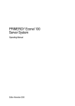
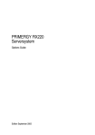
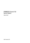
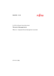
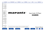
PRIMERGY SX650 Storage Blade
Operating Manual
Edition November 2008
Pfad: W:\Anwendungsdaten\FCT\tim_local\work\WALTER\OBJ_DOKU-3585-002.fm
© cognitas. Gesellschft für Technik-Dokumentation mbH 2008
Comments… Suggestions… Corrections…
The User Documentation Department would like to
know your opinion of this manual. Your feedback helps
us optimize our documentation to suit your individual
needs.
Feel free to send us your comments by e-mail to
[email protected].
Certified documentation
according to DIN EN ISO 9001:2000
To ensure a consistently high quality standard and
user-friendliness, this documentation was created to
meet the regulations of a quality management system
which complies with the requirements of the standard
DIN EN ISO 9001:2000.
cognitas. Gesellschaft für Technik-Dokumentation mbH
www.cognitas.de
Copyright and Trademarks
Copyright © 2008 Fujitsu Siemens Computers GmbH.
All rights reserved. Delivery subject to availability; right of technical modifications reserved.
All hardware and software names used are trade names and/or trademarks of their respective
manufacturers.
Contents
1
Preface . . . . . . . . . . . . . . . . . . . . . . . . . . . . . . 5
1.1
Concept and target groups for this manual
1.2
Documentation overview
1.3
Notational conventions
1.4
Technical Data . . . . . . . . . . . . . . . . . . . . . . . . . . 8
2
Important notes . . . . . . . . . . . . . . . . . . . . . . . . . 11
2.1
Notes on safety . . . . . . . . . . . . . . . . . . . . . . . . . 11
2.2
ESD label . . . . . . . . . . . . . . . . . . . . . . . . . . . . 13
2.3
CE conformity
2.4
RFI suppression . . . . . . . . . . . . . . . . . . . . . . . . 14
2.5
Notes on transport . . . . . . . . . . . . . . . . . . . . . . . 14
2.6
Environmental protection . . . . . . . . . . . . . . . . . . . 15
3
Installation . . . . . . . . . . . . . . . . . . . . . . . . . . . 17
3.1
Installation procedure . . . . . . . . . . . . . . . . . . . . . 18
3.2
Unpacking the storage blade . . . . . . . . . . . . . . . . . 18
3.3
Configuring a Second Storage Blade . . . . . . . . . . . . . 19
3.4
Shutting down the server blade . . . . . . . . . . . . . . . . 21
3.5
Installing the storage blade in the BX600 S3 basic unit or
removing it . . . . . . . . . . . . . . . . . . . . . . . . . . . 22
4
Installation and operation . . . . . . . . . . . . . . . . . . . 29
4.1
Control panel . . . . . . . . . . . . . . . . . . . . . . . . . . 29
4.2
Starting up the storage blade . . . . . . . . . . . . . . . . . 30
SX650
. . . . . . . . . . 6
. . . . . . . . . . . . . . . . . . . . 6
. . . . . . . . . . . . . . . . . . . . . 7
. . . . . . . . . . . . . . . . . . . . . . . . . 14
Operating Manual
Pfad: W:\Anwendungsdaten\FCT\tim_local\work\WALTER\OBJ_DOKU-3586-002.fm
© cognitas. Gesellschft für Technik-Dokumentation mbH 2008
Contents
5
Hot-plug components . . . . . . . . . . . . . . . . . . . . . . 31
5.1
hot-plug hard disk drives . . . . . . . . . . . . . . . . . . . . 31
5.2
Handling hard disk drives and HDD modules . . . . . . . . . 33
5.3
Removing/Installing the dummy module . . . . . . . . . . . . 34
5.4
Removing a hard disk module . . . . . . . . . . . . . . . . . 35
6
Troubleshooting and tips . . . . . . . . . . . . . . . . . . . . 39
Index
. . . . . . . . . . . . . . . . . . . . . . . . . . . . . . . . . . . . 41
Operating Manual
SX650
1
Preface
Figure 1: PRIMERGY SX650 Storage Blade
The PRIMERGY SX650 Storage Blade serves as a storage subsystem for the
PRIMERGY BX620 S4 server blade and its successors. The PRIMERGY
SX650 Storage Blade has 5 slots for 2.5-inch SAS or SATA hard disk modules
and occupies one slot in the PRIMERGY BX600 S3 basic unit.
You can connect one or two SX650 storage blades to one BX620 S4 server
blade. A second SX650 storage blade connected to a BX620 S4 server blade
must be configured for this purpose, see page 19.
The SX650 Storage Blade is connected to its associated server blade with a
special SAS cable.
SX650
Operating Manual
5
Pfad: W:\Anwendungsdaten\FCT\tim_local\work\WALTER\OBJ_DOKU-3587-002.fm
© cognitas. Gesellschft für Technik-Dokumentation mbH 2008
Concept and target groups for this manual
1.1
Preface
Concept and target groups for this manual
This operating manual describes how to install, set up and operate your server.
This operating manual is intended for those responsible for installing the
hardware and ensuring that the system runs smoothly. It contains all the information you need to put your PRIMERGYSX650 into operation.
To understand the various expansion options, you will need to be familiar with
the fields of hardware and data transmission and you will require a basic
knowledge of the underlying operating system.
1.2
Documentation overview
More information on your PRIMERGY SX650 Storage Blade can be found in the
following documents:
– “Safety notes and other important information” manual
– “Warranty” manual
– “Returning used devices” manual
I PRIMERGY manuals are available in PDF format on the ServerBooks
DVD. The ServerBooks DVD is part of the ServerView Suite supplied with
every server.
The PDF files of the manuals can also be downloaded free of charge
from the Internet. The overview page showing the online documentation
available on the Internet can be found using the URL:
http://manuals.fujitsu-siemens.com. The PRIMERGY server documentation
can be accessed using the Industry standard servers navigation option.
If you need a replacement copy of the ServerBooks DVD, send the
details of your server to the following e-mail address: [email protected]
6
Operating Manual
SX650
Preface
1.3
Notational conventions
Notational conventions
The following notational conventions are used in this manual:
Text in italics
“Quotation marks”
indicates commands or menu items.
indicate names of chapters and terms that are being
emphasized.
Ê
describes activities that must be performed in the order
shown.
V CAUTION!
I
SX650
pay particular attention to texts marked with this symbol.
Failure to observe this warning may endanger your life,
destroy the system or lead to the loss of data.
indicates additional information, notes and tips.
Operating Manual
7
Pfad: W:\Anwendungsdaten\FCT\tim_local\work\WALTER\OBJ_DOKU-3587-002.fm
© cognitas. Gesellschft für Technik-Dokumentation mbH 2008
Technical Data
1.4
Preface
Technical Data
electrical data
Energy consumption
Thermal dissipation
110 W (full configuration)
110 W
Compliance with regulations and standards
Product safety and
ergonomics
Electromagnetic
IEC 60950-1 / EN 60950-1, UL/CSA 60950-1,
CNS 14336 / GB 4943 / EN 50371
FCC class A
compatibility
CNS 13438 class A; VCCI class A
AS/NZS CISPR 22 class A / GB 9254 class A
GB 17625
Interference emissions EN 55022 class A
Harmonic current EN 61000-3-2
Flicker
EN 61000-3-3
Interference immunity
CE marking
EN 55024, EN 300386
Low Voltage Directive 2006/95/EC
to EU directives
(Product Safety)
Electromagnetic Compatibility 2004/108/EC
Certification
Product safety
Global
Europe
CB
ENEC
Germany
USA/Canada
Japan
GS, CE
CSAUS / CSAC
VCCI
China/Taiwan
BSMI
8
Operating Manual
SX650
Preface
Technical Data
Mechanical specifications
Width
Depth
Height
286 mm
470 mm (520 mm incl. handles and plugs)
43 mm (1 slot in basic unit)
Weight
Max. ca. 9,2 (Ausbau-abhängig) (depending on the configuration).
Ambient conditions
Environment class 3K2
Environment class 2K2
Temperature:
Operation (3K2)
EN 60721 / IEC 721 Part 3-3
EN 60721 / IEC 721 Part 3-2
Transport (2K2)
Humidity
-20°C .... 60°C
10% .... 85%
5°C .... 35°C
Condensation during operation must be avoided!
SX650
Operating Manual
9
© cognitas. Gesellschft für Technik-Dokumentation mbH 2008
Pfad: W:\Anwendungsdaten\FCT\tim_local\work\WALTER\OBJ_DOKU-3587-002.fm
2
Important notes
This chapter provides safety instructions which you must observe when
handling your storage blade.
2.1
Notes on safety
I The following safety instructions are also provided in the manual “Safety
notes and other important information”.
This device complies with the relevant safety regulations for IT equipment. If you
have any questions about whether you can install the server in the intended
environment, please contact your sales outlet or our customer service team.
V CAUTION!
●
The actions described in this manual should only be performed by
technical specialists.
●
Equipment repairs should only be performed by service staff.
●
Any failure to observe the guidelines in this manual, and any unauthorized opening or improper repairs could endanger the user (through
electric shock, fire hazards) or damage the equipment.
●
Please note that any unauthorized opening of the server will void the
warranty and exempt the manufacturer from all liability.
●
During installation and before operating the device, observe the
instructions on environmental conditions for your device (see section
“Technical Data” on page 8).
●
If the device is brought in from a cold environment, condensation may
form on both the inside and outside of the machine.
Before operating the device, wait until it is absolutely dry and has
reached approximately the same temperature as the installation site.
Failure to observe these guidelines could cause damage to the
device.
●
SX650
Transport the device only in its original packaging or in packaging
which protects it from knocks and jolts.
Operating Manual
11
Important notes
V CAUTION!
© cognitas. Gesellschft für Technik-Dokumentation mbH 2008
Pfad: W:\Anwendungsdaten\FCT\tim_local\work\WALTER\OBJ_DOKU-3588-002.fm
Notes on safety
12
●
Check that the rated voltage of all devices is the same as the local
mains voltage.
●
Do not connect or disconnect any data transmission cables during a
thunderstorm (lightning hazard).
●
Make sure that no objects (such as bracelets or paper clips etc.) fall
into or liquids spill into the device (risk of electric shock or short
circuit).
●
Proper operation of the system (in accordance with IEC609501/EN60950-1) is only guaranteed if slot covers are installed in all
vacant slots and/or dummies in all vacant bays and the housing cover
is fitted (cooling, fire protection, RFI suppression).
Operating Manual
SX650
Important notes
2.2
ESD label
ESD label
Modules with electrostatic-sensitive components
Systems and components that might be damaged by electrostatic discharge
(ESD) are marked with the following label:
Figure 2: ESD label
When you handle components fitted with ESDs, you must observe the following
points under all circumstances:
●
Remove the power plug before installing or removing components
containing ESDs.
●
You must always discharge yourself of static charges (e.g. by touching a
grounded object) before working.
●
The equipment and tools you use must be free of static charges.
●
Only touch the components at the positions highlighted in green (touch
points).
●
Do not touch any exposed pins or conductors on a component.
●
Use a grounding cable designed for this purpose to connect yourself to the
system unit as you install components.
●
Place all components on a static-safe base.
I You will find a detailed description for handling ESD components in the
relevant European or international standards (DIN EN 61340-5-1,
ANSI/ESD S20.20).
SX650
Operating Manual
13
Pfad: W:\Anwendungsdaten\FCT\tim_local\work\WALTER\OBJ_DOKU-3588-002.fm
© cognitas. Gesellschft für Technik-Dokumentation mbH 2008
CE conformity
2.3
Important notes
CE conformity
The system complies with the requirements of the EC directives
2004/108/EC regarding “Electromagnetic Compatibility” and
2006/95/EC “Low Voltage Directive”. This is indicated by the CE
marking (CE = Communauté Européenne).
2.4
RFI suppression
All other equipment which is connected to this product must also have radio
noise suppression in accordance with EC directive 89/336/EEC.
Products which meet this requirement are accompanied by a certificate to that
effect issued by the manufacturer and/or bear the CE mark. Products which do
not meet this requirement may only be operated with the special permission of
the German Federal Approvals Office for Telecommunications (BZT).
2.5
Notes on transport
I Transport the storage blade only in its original packaging or in packaging
which protects it from knocks and jolts.
Only unpack the storage blade at the place where you want to set it up.
14
Operating Manual
SX650
Important notes
2.6
Environmental protection
Environmental protection
Environmentally-friendly product design and development
This product has been designed in accordance with the Fujitsu Siemens
Computers standard for “environmentally friendly product design and development”. This means that key factors such as durability, selection and labeling
of materials, emissions, packaging, ease of dismantling and recycling have
been taken into account.
This saves resources and thus reduces the harm done to the environment.
Energy-saving information
Devices that do not need to be constantly switched on should be switched off
until they are needed as well as during long breaks and after completion of work.
Packaging information
Do not throw away the packaging. You may need it later for transporting the
system. If possible, the equipment should only be transported in its original
packaging.
Information on handling consumables
Please dispose of printer consumables and batteries in accordance with the
applicable national regulations.
In accordance with EU directives, batteries must not be disposed of with
unsorted domestic waste. They can be returned free of charge to the manufacturer, dealer or an authorized agent for recycling or disposal.
All batteries containing pollutants are marked with a symbol (a crossed-out
garbage can). They are also marked with the chemical symbol for the heavy
metal that causes them to be categorized as containing pollutants:
Cd Cadmium
Hg Mercury
Pb Lead
Labels on plastic casing parts
Please avoid sticking your own labels on plastic parts wherever possible, since
this makes it difficult to recycle them.
SX650
Operating Manual
15
Pfad: W:\Anwendungsdaten\FCT\tim_local\work\WALTER\OBJ_DOKU-3588-002.fm
© cognitas. Gesellschft für Technik-Dokumentation mbH 2008
Environmental protection
Important notes
Return, recycling and disposal
The device must not be disposed of with domestic waste. This
device is labeled in compliance with European directive 2002/96/EG
on waste electrical and electronic equipment (WEEE).
This directive sets the framework for returning and recycling used
equipment and is valid across the EU. When returning your used
device, please use the return and collection systems available to
you. Further information can be found at www.fujitsusiemens.com/recycling.
Details regarding the return and recycling of devices and consumables within
Europe can also be found in the “Returning used devices” manual, via your local
Fujitsu Siemens Computers branch or from our recycling center in Paderborn:
Fujitsu Siemens Computers GmbH
Recycling Center
D-33106 PaderbornGermany
Tel.
+49 5251 8 18010
Fax
+49 5251 8 18015
16
Operating Manual
SX650
3
Installation
V CAUTION!
●
Follow the safety instructions in chapter chapter “Important notes” on
page 11.
●
The storage blade must not be exposed to extreme environmental
conditions (see section “Technical Data” on page 8). Protect the
storage blade from dust, humidity and heat.
●
The storage blade must be acclimatized to its operating environment
for the time specified in the table before you operate it.
Temperature difference (°C)
Minimum acclimatization time
(hours)
5
3
10
5
15
7
20
8
25
9
30
10
Table 1: Acclimatization times
In table “Acclimatization times”, temperature difference refers to the
difference between the temperature of the operating environment and
the temperature to which the storage blade was previously exposed
(outside, transport or storage temperature).
SX650
Operating Manual
17
Pfad: W:\Anwendungsdaten\FCT\tim_local\work\WALTER\OBJ_DOKU-3589-002.fm
© cognitas. Gesellschft für Technik-Dokumentation mbH 2008
Installation procedure
3.1
Installation
Installation procedure
Ê Unpacking the storage blade (see next section “Unpacking the storage
blade”).
The following step is only necessary if you want to connect two storage blades to
one server blade:
Ê Configuring a second storage blade (see page 19).
Ê Shutting down the associated server blade (see section “Shutting down the
server blade” on page 21).
Ê section “Installing the storage blade in the BX600 S3 basic unit or removing
it” on page 22Installing the storage blade in the basic unit
Ê Connecting the cables of the storage blade (see next section “Installing the
storage blade in the BX600 S3 basic unit or removing it” on page 25).
Ê Starting up the storage blade (see section “Starting up the storage blade” on
page 30 in the chapter “Installation and operation”).
3.2
Unpacking the storage blade
V CAUTION!
Make sure you observe the safety notes in the chapter “Important notes”.
Keep the original packaging of the storage blade, as you may need it for future
transport.
Ê Unpack all the individual parts.
Ê Check the delivery for damage sustained during transport.
Ê Check that the delivery corresponds to the specifications in the delivery
note.
Ê Check whether all the necessary details have been entered on the first page
of the guarantee booklet.
If the delivery is damaged or does not match the delivery note, contact your
supplier immediately!
18
Operating Manual
SX650
Installation
3.3
Configuring a Second Storage Blade
Configuring a Second Storage Blade
V CAUTION!
Make sure you observe the safety notes in the chapter “Important notes”.
You can connect two SX650 storage blades to one BX620 S4 server blade. For
the hard disk drives of both storage blades to be correctly addressed by the
server blade, the SAS ID for the second storage blade must be increased by 1.
This is done via a jumper setting on the SAS expander board of the second
storage blade.
This section describes how to make this setting. You will need to open the
housing of the second storage blade.
Figure 3: Opening the storage blade
Ê Press down the two top cover release latches (1) simultaneously to
disengage the locking mechanism of the cover plate and slide the cover
plate backward in the direction of the arrow (2).
Ê Take off the cover plate.
The server blade components are now freely accessible.
SX650
Operating Manual
19
Pfad: W:\Anwendungsdaten\FCT\tim_local\work\WALTER\OBJ_DOKU-3589-002.fm
© cognitas. Gesellschft für Technik-Dokumentation mbH 2008
Configuring a Second Storage Blade
Installation
Figure 4: Plupping the jumper
Ê Set the jumper to the position shown in the figure above, so that pins 1 and
2 of jumper block J4 are connected.
I In the default setting, the jumper is set via a single pin.
20
Operating Manual
SX650
Installation
Shutting down the server blade
Close the housing of the second storage blade now.
Figure 5: Closing the storage blade
Ê Place the cover plate evenly on the server blade chassis, leaving a gap of
approx. 1-2 cm (1 inch) from the front frame of the chassis.
Ê Slide the cover plate forward in the direction of the arrows until it stops.
3.4
Shutting down the server blade
Before installing SX650 Storage Blades in the BX600 S3 basic unit, you must
shut down the associated server blade. To do this, use the Web interface of the
BX600 S3 management blade, see the manual “PRIMERGY BX Blade Server
Systems - RemoteView Management Blade”.
SX650
Operating Manual
21
3.5
Installation
Installing the storage blade in the BX600 S3
basic unit or removing it
V CAUTION!
Make sure you observe the safety notes in the chapter “Important notes”
on page 11.
Fitting rules
© cognitas. Gesellschft für Technik-Dokumentation mbH 2008
Pfad: W:\Anwendungsdaten\FCT\tim_local\work\WALTER\OBJ_DOKU-3589-002.fm
Installing the storage blade in the BX600 S3 basic unit
1
2
3
4
5
6
7
8
9
10
Figure 6: Numbering of the server blade slots
The SX650 Storage Blades must be installed to the immediate right of the
associated server blade. So if the associated server blade is installed in slot n,
you must install the first storage blade in slot n+1 and the second storage blade
in slot n+2.
Removing the dummy module
Any unused slots in the basic unit are fitted with appropriate dummy modules to
comply with electromagnetic compatibility (EMC) regulations and to ensure
sufficient cooling of the system components.
To add a storage blade, you must first remove the dummy module from the
relevant slot.
22
Operating Manual
SX650
Installation
Installing the storage blade in the BX600 S3 basic unit
!
Figure 7: Removing the dummy module
Ê Undo the locking mechanism of the handles by pressing the green touch
points on the inside of the two handles (1). This undoes the locking handles
of the dummy module.
Ê Swivel the top handle upward and the bottom handle downward (2) simultaneously until the locking mechanism of the dummy module disengages and
releases the module.
Ê Pull the dummy module completely out of the slot (3).
V CAUTION!
Keep the dummy module for future use. If a storage blade or server blade
is removed again and not replaced with a new one, the dummy module
must be reinstalled because of cooling, EMC regulations, and fire
protection.
You install the dummy module in the same way as the storage blade. This is
described in the following section.
SX650
Operating Manual
23
Installation
Installing a storage blade
V CAUTION!
Make sure you observe the safety instructions and note the information
in section “ESD label” on page 13.
2
© cognitas. Gesellschft für Technik-Dokumentation mbH 2008
Pfad: W:\Anwendungsdaten\FCT\tim_local\work\WALTER\OBJ_DOKU-3589-002.fm
Installing the storage blade in the BX600 S3 basic unit
1
I Make sure you install the
storage blade in the correct
direction. The SAS connector
(A) must be in the bottom part of
the storage blade.
Ê Undo the locking mechanism of the
storage blade handles by first
pressing the green inside touch
points of the two handles (1).
Ê Then swivel the locking handles
outward (2) into the unlocked
position.
Ê Holding the locking handles in the
unlocked position, push the storage
blade as far as possible into the
slot.
Ê Press the locking handles inwards
until the locking mechanism of the
storage blade engages fully.
1
A
2
Figure 8: Installing a storage blade
24
Operating Manual
SX650
Installation
Installing the storage blade in the BX600 S3 basic unit
Connecting the first storage blade
Figure 9: Connecting the storage blade
Ê Connect the bottom SAS connector of the server blade and the SAS
connector of the storage blade using the supplied short SAS cable.
SX650
Operating Manual
25
Installation
Connecting the Second Storage Blade
V CAUTION!
Make sure that the SAS ID for the storage blade is set correctly, see
“Configuring a Second Storage Blade” on page 19.
© cognitas. Gesellschft für Technik-Dokumentation mbH 2008
Pfad: W:\Anwendungsdaten\FCT\tim_local\work\WALTER\OBJ_DOKU-3589-002.fm
Installing the storage blade in the BX600 S3 basic unit
Figure 10: Connecting the second storage blade
Ê Connect the upper BX620 S4 SAS connector to the SAS connector of the
second storage blade using the supplied longer SAS cable.
26
Operating Manual
SX650
Installation
Installing the storage blade in the BX600 S3 basic unit
Removing a storage blade
V CAUTION!
If you remove a storage blade and do not install a new blade in its place,
you must install a dummy module in the empty slot.
Ê Make sure the server blade to which the storage blade is connected is
switched off.
Ê Remove the miniSAS cable from the SAS connectors of the storage blade
and the server blade (see figure 9).
Ê Remove the storage blade from the basic unit in the same way as you would
remove a dummy module (see “Removing the dummy module” on page 22).
SX650
Operating Manual
27
© cognitas. Gesellschft für Technik-Dokumentation mbH 2008
Pfad: W:\Anwendungsdaten\FCT\tim_local\work\WALTER\OBJ_DOKU-3589-002.fm
4
Installation and operation
4.1
Control panel
1
2
3
4
Figure 11: Control panel
LEDs and connectors
1
2
Hard disk access (green LED)
Dark:
Hard disk drive not active.
Glows
green:
Hard disk drive active.
Hard disk drive indicator (orange LED)
Dark:
No error
Glows
orange:
Server blade is on and hard disk drive has an error.
Flashes
Reconstruction (RAID message)
slowly (1Hz)
Flashes
Indicates hard disk localization (RAID message)
quickly (3Hz)
SX650
Operating Manual
29
Pfad: W:\Anwendungsdaten\FCT\tim_local\work\WALTER\OBJ_DOKU-3590-002.fm
© cognitas. Gesellschft für Technik-Dokumentation mbH 2008
Starting up the storage blade
3
4
4.2
Installation and operation
Power indicator (green LED)
Glows:
The connected server blade is running.
Dark:
The connected server blade is not running.
SAS connector
Starting up the storage blade
Make sure the storage blade is installed in the basic unit and connected to the
associated server blade (see sections “Installing the storage blade in the BX600
S3 basic unit or removing it” on page 22 and “Connecting the first storage blade”
on page 25).
Ê Start the server blade that is connected to the storage blade either via the
Web interface of the management blade or by pressing the On/Off button on
the control panel of the server blade.
As soon as the associated server blade is in operation, the power indicator of
the storage blade lights up. You can now configure the hard disk drives of the
storage blade using the ServerView RAID Manager. For more information, see
the user manual “ServerView RAID Version 2.3”.
I You start up two storage blades on one server blade in the same way.
30
Operating Manual
SX650
5
Hot-plug components
This chapter describes how to replace or add hot-plug hard disk drives in the
PRIMERGYSX650 Storage Blade.
You can install up to five 2.5-inch SAS or SATA hard disk drives in the
PRIMERGY SX650 Storage Blade.
I You cannot operate both SAS and SATA hard disk drives together in the
same storage blade.
Fitting rules
The bays for the hard disk modules must be fitted in the order shown in the
following figure. If you install hard disk modules with different capacities, install
the modules in order of ascending capacity (0-4).
HDD 4
HDD 3
HDD 1
HDD 2
HDD 0
Figure 12: Fitting order for hard disk modules
5.1
hot-plug hard disk drives
The hard disk drives that can be ordered for the SX650 Storage Blade come
mounted in a module frame that allows you to replace defective drives and add
new ones while the system is running. The hard disk drive and the module frame
are together referred to as the hard disk module.
V CAUTION!
SX650
●
A hard disk should only be removed from the hard disk module by a
service technician.
●
All hard disk modules (drives) must be clearly labeled so that you can
replace them in their original bays should you remove them. If you mix
up the hard disks you might lose existing data.
Operating Manual
31
Hot-plug components
V CAUTION!
●
“Hot plugging” is only possible in conjunction with a corresponding
RAID configuration.
For more information on RAID configurations or RAID levels, see the
RAID controller documentation.
© cognitas. Gesellschft für Technik-Dokumentation mbH 2008
Pfad: W:\Anwendungsdaten\FCT\tim_local\work\WALTER\OBJ_DOKU-3591-002.fm
hot-plug hard disk drives
Figure 13: 2.5-inch hard disk module and dummy module
1
Hard disk module (carrier with installed hard disk drive)
2
Indicators
HDD busy (LED green)
HDD fault (LED orange)
Description see table on page 29 in section “Control panel”.
3
Handle for engaging and disengaging the hard disk module
4
Locking button
5
Indentation for a sticker with the current drive identifier
6
Dummy module
7
Locking tabs of the dummy module
32
Operating Manual
SX650
Hot-plug components
5.2
Handling hard disk drives and HDD modules
Handling hard disk drives and HDD
modules
Hard disk drives incorporated in the HDD modules are highly sensitive electromagnetic devices and must be handled with great care. Incorrect handling can
cause partial or total failure of the hard disk drives. These failures can result in
data errors and to a loss of data or to total corruption of the hard disk drive.
Observe the following rules to prevent such problems occurring:
●
Only store and transport HDD modules within the limits stipulated in the
specification.
●
When transporting HDD modules (even over short distances), always use
the original packaging (ESD label).
●
Never expose HDD modules to a temperature shock. Avoid the formation of
condensation inside and on the outside of the hard disk drive.
V CAUTION!
The HDD module must be acclimatized in its operating environment
for an acclimatization time before it is started up for the first time.
Temperature difference (°C)
Minimum acclimatization time
(operating environment/
(hours)
outside)
5
3
10
5
15
7
20
8
25
9
30
10
Table 2: Acclimatization times for HDD modules
●
Always set the HDD module down carefully, with the large surface facing
downwards to prevent it from tipping over.
SX650
Operating Manual
33
5.3
Hot-plug components
Removing/Installing the dummy module
Free slots are provided with dummy modules. Remove the dummy module
before installing an additional HDD module.
1
© cognitas. Gesellschft für Technik-Dokumentation mbH 2008
Pfad: W:\Anwendungsdaten\FCT\tim_local\work\WALTER\OBJ_DOKU-3591-002.fm
Removing/Installing the dummy module
2
1
Figure 14: Removing the dummy module
Ê Press both tabs on the dummy module together until the locking mechanism
disengages (1).
Ê Pull the dummy module out of the slot (2).
To install a dummy module, follow the same procedure in reverse order.
V CAUTION!
Store the dummy module in a safe place. If you have removed an HDD
module and do not install a new one in its place, put the dummy module
back in its place for cooling, to comply with EMC regulations (regulations
regarding electromagnetic compatibility), and for protection against fire.
Ensure that the dummy module engages correctly in the slot.
34
Operating Manual
SX650
Hot-plug components
5.4
Removing a hard disk module
Removing a hard disk module
Unlocking the hard disk module
2
1
Figure 15: Unlocking a 2.5-inch hard disk module
– Press the green locking lever to the left (1) and swivel the locking handhold
to the front (2).
SX650
Operating Manual
35
Pfad: W:\Anwendungsdaten\FCT\tim_local\work\WALTER\OBJ_DOKU-3591-002.fm
© cognitas. Gesellschft für Technik-Dokumentation mbH 2008
Removing a hard disk module
Hot-plug components
Installing a hard disk module
Figure 16: Installing a hard disk module
Ê Carefully push the hard disk module into the empty bay as far as it will go.
Ê Swivel the handle fully round in the direction of the arrow until the locking
mechanism engages.
Removing the HDD module
V CAUTION!
●
Only remove a HDD module during operation if the drive is not
currently being accessed. Observe the control LEDs for the corresponding HDD modules (see “Control panel” on page 29).
●
Under no circumstances should you remove an HDD module while
the system is in operation if you are not sure whether the hard disk
drive is operated by a RAID controller and belongs to a disk array
which is operating at RAID level 1.
An HDD module can only be replaced during operation in conjunction
with a corresponding RAID configuration.
●
All HDD modules (drives) must be uniquely identified so that they can
be reinstalled in their original mounting locations later. If this is not
done, existing data can be lost.
If you want to remove an HDD module during operation, proceed as follows:
Ê If you want to remove a HDD module that is not defective, the drive must be
first set to offline via the software (RAID controller configuration software).
Ê Unlock the HDD module as described in section “Unlocking the hard disk
module” on page 35.
Ê Pull the HDD module out a few centimeters.
36
Operating Manual
SX650
Hot-plug components
Removing a hard disk module
Ê Wait for at least 60 seconds.
I This period is necessary for the RAID controller to recognize that an
HDD module has been removed and for the hard disk drive to come
to a stop.
Ê Pull the HDD module out completely.
Ê Install the new HDD module, as described in “Unlocking the hard disk
module” on page 35 and “Installing a hard disk module” on page 36.
V CAUTION!
If you have removed an HDD module and do not install a new one in
its place, put the dummy module back in its place for cooling, to
comply with EMC regulations (regulations regarding electromagnetic
compatibility), and for protection against fire. Ensure that the dummy
module engages correctly in the slot.
SX650
Operating Manual
37
© cognitas. Gesellschft für Technik-Dokumentation mbH 2008
Pfad: W:\Anwendungsdaten\FCT\tim_local\work\WALTER\OBJ_DOKU-3591-002.fm
6
Troubleshooting and tips
V CAUTION!
Make sure you observe the safety notes in the chapter “Important notes”
on page 11.
If the power indicator of the storage blade (see figure 11 on page 29) does not
light up after you have switched on the associated server blade, note the
following:
All handling errors that may occur while operating server blades in the
PRIMERGY BX600 S3 basic unit are described in the operating manual for the
basic unit.
If a fault occurs, try to correct it as described:
– in the chapter “Troubleshooting and tips” in the operating manual for your
basic unit.
– in the chapters for the installed components,
– in the documentation for the connected devices
– in the help systems of the individual programs used.
If you do not manage to correct the problem, proceed as follows:
Ê Make a note of the steps you have taken and the situation in which the fault
occurred. Also make a note of the error messages displayed.
Ê Switch off the defective server blade or the system.
Ê Contact customer service.
SX650
Operating Manual
39
© cognitas. Gesellschft für Technik-Dokumentation mbH 2008
Pfad: W:\Anwendungsdaten\FCT\tim_local\work\WALTER\OBJ_DOKU-3592-002.fm
Index
A
acclimatization time 17, 33
ambient conditions 9
module frame 35
HDD module
acclimatization time
C
CE marking 8, 14
certification
product safety 8
compliance standards 8
connector 30
consumables 15
control panel 29
L
labels 15
Low Voltage Directive
D
display elements 29
disposal, of devices 16
dummy module
remove 22
dummy module, HDD module
SX650
8, 14
M
meaning of the symbols
7
N
norms and standards 8
notational conventions 7
notes on safety 11
P
packaging
34, 37
E
electrical data 8
electromagnetic compatibility 8, 14
EMC directive 8
EMC regulations 34, 37
environment class 9
environmental protection 15
ESD (devices sensitive to electrostatic
discharge) 13
H
hard disk drive
handling 33
hard disk module 31
module frame 31
replacing online 36
hard disk module
acclimatization time 17
dummy module 31
handling 31
install/remove 35
33
15
R
recycling, of devices 16
remove
dummy module 22
replacing online 36
return, of devices 16
RFI suppression 14
S
safety standards 8
saving energy 15
server
ambient conditions 9
compliance standards 8
safety standards 8
Steckbrücke 19
Storage Blade
zweites konfigurieren 19
storage blade
dimensions 9
electrical data 8
safety standards 8
weight 9
Operating Manual
41
© cognitas. Gesellschft für Technik-Dokumentation mbH 2008
Pfad: W:\Anwendungsdaten\FCT\tim_local\work\WALTER\OBJ_DOKU-3593-002.fm
Index
T
target group 6
technical data 8
U
unpack
W
weight
42
18
9
Operating Manual
SX650
Information on this document
On April 1, 2009, Fujitsu became the sole owner of Fujitsu Siemens Computers. This new subsidiary of Fujitsu has been renamed Fujitsu Technology Solutions.
This document from the document archive refers to a product version which
was released a considerable time ago or which is no longer marketed.
Please note that all company references and copyrights in this document have
been legally transferred to Fujitsu Technology Solutions.
Contact and support addresses will now be offered by Fujitsu Technology Solutions and have the format …@ts.fujitsu.com.
The Internet pages of Fujitsu Technology Solutions are available at
http://ts.fujitsu.com/...
and the user documentation at http://manuals.ts.fujitsu.com.
Copyright Fujitsu Technology Solutions, 2009
Hinweise zum vorliegenden Dokument
Zum 1. April 2009 ist Fujitsu Siemens Computers in den alleinigen Besitz von
Fujitsu übergegangen. Diese neue Tochtergesellschaft von Fujitsu trägt seitdem den Namen Fujitsu Technology Solutions.
Das vorliegende Dokument aus dem Dokumentenarchiv bezieht sich auf eine
bereits vor längerer Zeit freigegebene oder nicht mehr im Vertrieb befindliche
Produktversion.
Bitte beachten Sie, dass alle Firmenbezüge und Copyrights im vorliegenden
Dokument rechtlich auf Fujitsu Technology Solutions übergegangen sind.
Kontakt- und Supportadressen werden nun von Fujitsu Technology Solutions
angeboten und haben die Form …@ts.fujitsu.com.
Die Internetseiten von Fujitsu Technology Solutions finden Sie unter
http://de.ts.fujitsu.com/..., und unter http://manuals.ts.fujitsu.com finden Sie die
Benutzerdokumentation.
Copyright Fujitsu Technology Solutions, 2009