1
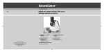
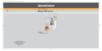
System POLYMIX® PX-MFC 90 D Operating Instructions Carefully read the manual before starting operation or disassembling! Please check that the voltage is correct and corresponds with the nameplate on the back of the machine. Voltage 100...120 V, 50/60 Hz 210...250 V, 50/60 Hz This is a quality product made by Luzernerstrasse 147a CH-6014 Luzern Switzerland Tel.: Fax: e-mail: +41-41-259 65 65 +41-41-259 65 75 [email protected] CONTENT: 1 INTRODUCTION....................................................................................................................................... 3 1.1 1.2 1.3 2 SAFETY .................................................................................................................................................... 7 2.1 2.2 2.3 2.4 3 OVERVIEW .................................................................................................................................... 13 DRIVE UNIT ................................................................................................................................... 16 GRINDING ATTACHMENTS ......................................................................................................... 16 TOOLS AND ACCESSORIES ....................................................................................................... 18 TECHNICAL SPECIFICATIONS .................................................................................................... 19 INSTALLATION...................................................................................................................................... 20 4.1 4.2 4.3 5 SUMMARY ....................................................................................................................................... 7 SAFETY CONCEPT......................................................................................................................... 7 RESIDUAL DANGERS................................................................................................................... 10 WARNINGS.................................................................................................................................... 11 DESCRIPTION OF THE MACHINE ....................................................................................................... 13 3.1 3.2 3.3 3.4 3.5 4 OPERATING INSTRUCTIONS ........................................................................................................ 3 ORGANISATIONAL MATTERS ....................................................................................................... 5 WARNING NOTICES ....................................................................................................................... 6 UNPACK......................................................................................................................................... 20 START UP...................................................................................................................................... 20 EXCHANGE OF GRINDING ATTACHMENTS .............................................................................. 23 MAINTENANCE...................................................................................................................................... 27 5.1 5.2 5.3 DRIVE SYSTEM............................................................................................................................. 28 CLEANING & MAINTENANCE ...................................................................................................... 28 SPARE PARTS LIST...................................................................................................................... 33 6 TROUBLE SHOOTING .......................................................................................................................... 34 7 ACCESSORIES ...................................................................................................................................... 35 8 WARRANTY ........................................................................................................................................... 36 APPENDIX A. DIMENSIONAL DRAWINGS ............................................................................................ 37 APPENDIX B. PARTS LISTS ................................................................................................................... 38 Manual PX-MFC 90 D english / Release 2.3 / 14.04.2010 page 2 of 39 1 INTRODUCTION This chapter gives information on the the structure of this document. It will assist you in making use of it and show how to find the required information quickly. 1.1 OPERATING INSTRUCTIONS Please read through these operating instructions before switching on or attempting to use the equipment. They describe the use of the POLYMIX PX-MFC 90 D, its installation and maintenance and the appropriate replacement parts and accessories. They will help you avoid erroneous use and consequent damage. Although POLYMIX machines are designed for ease of service, this does not release you from the obligation to inspect your equipment carefully and to clean it thoroughly. KINEMATICA AG is a specialist manufacturer of machines and equipment for dispersion and mixing technology. An important objective of these operating instructions is to fully inform you, the user, about the correct and safe use of our equipment. In order to achieve this, it is essential that you should carefully study chapter 2, “Safety”, and follow the instructions in this book. Manual PX-MFC 90 D english / Release 2.3 / 14.04.2010 page 3 of 39 1.1.1 RANGE OF VALIDITY The information in these operating instructions relates to the POLYMIX® identified as follows: Manufacturer: Brand name: Product name: Order code 35010020 35010021 35010022 35010023 35010030 35010031 35010032 35010033 KINEMATICA AG, CH-6014 Luzern POLYMIX® POLYMIX® PX-MFC 90 D Identifier Drive POLYMIX® PX-MFC 90 D, hammer-grinding attachment, tools Drive POLYMIX® PX-MFC 90 D, hammer-grinding attachment, tools Drive POLYMIX® PX-MFC 90 D, hammer-grinding attachment, tools Drive POLYMIX® PX-MFC 90 D, hammer-grinding attachment, tools Drive POLYMIX® PX-MFC 90 blade-grinding attachment, tools Drive POLYMIX® PX-MFC 90 blade-grinding attachment, tools Drive POLYMIX® PX-MFC 90 blade-grinding attachment, tools Drive POLYMIX® PX-MFC 90 blade-grinding attachment, tools 115 V, with US-power cable, 230 V, with EU-power cable, 230 V, with CH-power cable, 230 V, with GB-power cable, D, 115 V, with US-power cable, D, 230 V, with EU-power cable, D, 230 V, with CH-power cable, D, 230 V, with GB-power cable, 35031001 35031002 hammer-grinding attachment for PX-MFC 90 D blade-grinding attachment for PX-MFC 90 D 35080001 Stodger tool for stringy materials Manual PX-MFC 90 D english / Release 2.3 / 14.04.2010 page 4 of 39 1.1.2 TARGET AUDIENCE These operating instructions are intended for all authorised users of our machines/equipment. We distinguish different user roles, taking account of the different demands placed on the user by the activity to be carried out. You will find the definitions of user roles with the demands on the user in chapter 2, “Safety”. You can fulfil one or more of these roles, provided that you meet the corresponding demands. 1.2 ORGANISATIONAL MATTERS If you are unable to find the answer to any question in the operating instructions, please contact the equipment manufacturer directly. 1.2.1 LOCATION OF THE OPERATING INSTRUCTIONS The operating instructions can only be of use to you if you always have them to hand. They should, therefore, always be kept at the place where the equipment is used. 1.2.2 MANUFACTURER AND CONTACT ADDRESS KINEMATICA AG Luzernerstrasse 147a CH-6014 Luzern TEL: +41 41 259 65 65 FAX: +41 41 259 65 75 e-mail: [email protected] Manual PX-MFC 90 D english / Release 2.3 / 14.04.2010 page 5 of 39 1.3 WARNING NOTICES Please be aware of the meaning of the following warning signs: ATTENTION DANGER / WARNING! OBSERVE OPERATING INSTRUCTIONS. ATTENTION! DANGER OF ELECTRIC SHOCK. ATTENTION! WARNING OF HOT SURFACE. ATTENTION! MACHINE NOT SUITED FOR USE IN EX-AREAS Manual PX-MFC 90 D english / Release 2.3 / 14.04.2010 page 6 of 39 2 SAFETY This chapter is directed at all users of KINEMATICA laboratory equipment. It includes information on safe and optimum use. 2.1 SUMMARY Any incorrect use of the installed equipment can be dangerous. Inadequately trained users can cause material damage and personal injury. This chapter informs you of the safety concept and the requirements for safe and optimum use of the equipment. All those authorised to operate, service and repair the equipment are required to study chapter 2, “Safety”. 2.2 SAFETY CONCEPT The safety concept sets down the entitlement to use the equipment and the responsibilities of the individual users. The machines and equipment are designed and constructed according to the state of the art and the recognised safety rules. 2.2.1 INTENDED USE OF THE EQUIPMENT The equipment is designed and constructed for the following use: Cutting and milling of dry products in accordance with the technical specifications (see point 3.5) and compatibility with the materials coming into contact with the products. If you use the equipment for any purpose other than those listed, the manufacturer cannot be held liable for any resulting damage. 2.2.2 IMPROPER USE Any use other than the “proper use” without the written approval of the manufacturer or operation outside the technical limits of use is improper use. Manual PX-MFC 90 D english / Release 2.3 / 14.04.2010 page 7 of 39 2.2.3 USER ROLES To guarantee safety, we place requirements on the users of the equipment that must be met without fail. Only persons meeting the requirements are authorised to work with the equipment. We describe all those who work with the equipment as users. Since the requirements of these users are very much dependent on their activity, we distinguish the following user roles. Contract partner: The manufacturer can impose legal obligations on the contract partner when the equipment is purchased. The contract partner is obliged to ensure that the equipment is properly used. Operating company: The operating company ensures that the equipment is properly used and authorises persons who are entitled to work with the equipment in any one of the defined user roles. He is under the obligation to instruct the users. Note: Contract partner and operating company can be the same person. Service technician: The service technician is an employee of the operating company and looks after the equipment in special operating mode(s). He is a specialist with mechanical, electrical and electronic professional training. The service technician undertakes commissioning, decommissioning service and repair of the equipment. He must be appropriately trained to be able to carry out the service work required. Operator: The operator turns the equipment on and off. In the event of an alarm signal he informs the service technician. Manual PX-MFC 90 D english / Release 2.3 / 14.04.2010 page 8 of 39 2.2.4 DANGER AREA System/equipment The system danger area includes the whole system/equipment including the connecting lead and controls. Proximity danger area This refers to all areas within a defined distance of the equipment. User danger area This danger area includes all persons working with the equipment. 2.2.5 AREAS OF RESPONSIBILITY In order that the system/equipment can be used safely and without risk, the users in various roles bear the responsibility for particular danger areas. Contract partner: The contract partner bears the responsibility for the “proximity danger area”. Operating co mpany: The operating company bears the responsibility for the “user danger area”. Only those users may be authorised to operate the system/equipment who fulfil all requirements of the user roles concerned. In so doing, attention must be paid to the following points: It is to be ensured that all users of the system/equipment have fully read and understood chapter 2, “Safety” and act accordingly in a safety-conscious manner. It is to be ensured that no unauthorised person carries out work with the system/equipment. It is to be ensured that users are informed of the possible risks and dangers connected with the system/equipment. It is to be ensured that those being trained or engaged in general training are under the permanent supervision of a trained and authorised person. Manual PX-MFC 90 D english / Release 2.3 / 14.04.2010 page 9 of 39 Service technician: The service technician bears the responsibility for the “system/equipment danger area”. He ensures that the system/equipment is at all times free from technical faults, safe and functions correctly. 2.2.6 GENERAL SAFETY RULES Observe the following general safety rules: follow these operating instructions, in addition, observe the legal obligations and requirements for accident prevention and environmental protection of the country in which you operate the equipment, do not make any modifications to the equipment without the written authorisation of the manufacturer, only original replacement parts may be used for repairs, before any service work on the equipment, it must be ensured that the electrical supply is switched off, after any service, maintenance or repair work has been carried out on the system/equipment, it must be given a test run by the service technician. depending on the place at which it is installed, circumstances may require that hearing protection is worn when remaining in the vicinity of the equipment for long periods. 2.3 RESIDUAL DANGERS When the system/equipment is used in accordance with rules and regulations, residual dangers are minimal. Residual danger Tripping over connecting cables Breaking of glass containers Product spurting out Damage to hearing by continuous exposure to noise Tilting of machine Remedy Adequate installation Wear eye protection. Close lid. Wear ear protection according to duration and nature of task. Use non-slip, sturdy and horizontal base pad. Manual PX-MFC 90 D english / Release 2.3 / 14.04.2010 page 10 of 39 AN EXPERT ELECTRICIAN MUST CARRY OUT ALL ELECTRICAL INSTALLATIONS 2.4 WARNINGS • Make sure that the voltage of electric power source corresponds with machine. • Exchange grinding geometries only after electric power supply has been disconnected.. • The electric power supply system, to which the machine is connected, must comply with the requirements stipulated on the nameplate in order to ensure a flawless functioning. • If hazardous chemicals or harmful materials can impact the environment or the usage of the equipment, adequate corrective action has to be taken. • During longer operation and high load the grinding chamber can warm up significantly – risk of light burns.. • The machine must not be operated in explosion-prone rooms (highly flammable gases, fluids, solids or dust in the environment) • Make sure that during the grinding of certain products no explosive dust atmosphere is generated. If strong formation of dust occurs during grinding, work under extractor hood WARNINGS: To be continued on next page Manual PX-MFC 90 D english / Release 2.3 / 14.04.2010 page 11 of 39 WARNINGS: continuation • Only service specialists authorised by KINEMATICA AG may open the machine. • The areas around the ventilation grille and the ventilation slots at the back of the machine must always remain unobstructed in order to ensure efficient cooling. If cooling is not sufficient, performance will decrease. • The machine has to be installed in a way that no dirt or liquid can enter via the ventilation slots. • Only dry, preferably non-fatty products may be ground. • Exchange grinding geometries only after electric power supply has been disconnected. • Make sure that the grinding geometries are thoroughly cleaned after each usage. • The grinding chamber must not be opened during operation. • For the feeding of stringy materials only the optional tamper (order No. 35080001) may be used. Using other objects may cause destruction of the grinding unit and/or injuries. • Never manipulate with hands or tools in/around the open grinding chamber while electric power cable is connected. • Never grab down into the open hopper. Products made by KINEMATICA AG comply with all established and relevant CE-regulations; they carry the CE-label and are delivered with a corresponding declaration of conformity. Manual PX-MFC 90 D english / Release 2.3 / 14.04.2010 page 12 of 39 3 DESCRIPTION OF THE MACHINE The PX-MFC 90 D complies with all established and relevant CE-regulations, it carries the CE-label and is delivered with a corresponding declaration of conformity. 3.1 OVERVIEW The POLYMIX® PX-MFC 90 D is a lab mill, suited for grinding batches of dry substances. By exchanging the grinding geometries the mill can be converted into a hammer mill or a cutting mill. The mill is not designed for continuous operation. For a serviceable system you need to have: • • • • • The drive unit PX-MFC 90 D with power cable A milling-set (hammer mill set or cutting mill set) A sieve Collecting basin Power supply according to nameplate On the following page you find a picture of the complete system PX-MFC 90 D with legend and explanation of components. MAKE SURE THAT ONLY DRY SUBSTANCES WITH A FAT CONTENT AS LOW AS POSSIBLE ARE GROUND. HIGHLY HUMID OR FATTY SUBSTANCES CAN CAUSE PLUGGING AND ACCUMULATION OF MATERIALS AT THE SIEVE AND THE GRINDING GEOMETRIES. Manual PX-MFC 90 D english / Release 2.3 / 14.04.2010 page 13 of 39 Grab handle for relocation Display for rotation speed indicator and alarms Turning knob for speed adjustment Main switch . Fig. 1 Cooling air intake Cooling air outlet Connector plug for power cable Fig. 2 Manual PX-MFC 90 D english / Release 2.3 / 14.04.2010 Rubber foot (5x) page 14 of 39 Hopper lid Hopper for feeding product Metering Knurled screw for fixing/ loosening the metering Knurled screw for opening/ closing the chamber Knurled screw for fixing/ loosening the Stators (6x) Flange for NS29/32 – vessels Product outlet Manual PX-MFC 90 D english / Release 2.3 / 14.04.2010 page 15 of 39 3.2 DRIVE UNIT The drive unit PX-MFC 90 D is equipped with a strong 1000 W motor and is switched on via the main switch on the front side of the machine. The machine disposes of an integrated electronic control system. Rotating speeds between 0 – 6000 rpm can be set. Maximum power is reached between 4500 and 5000 rpm. The electronic control system disposes of safety functions, which induce an emergency shutdown in case of overheating or jamming of the drive unit, along with a corresponding alarm on the display. After an emergency shutdown the machine has to be restarted. The unit is also equipped with a safety function which prevents the motor getting started when the milling door is still open – The milling chamber has to be closed using the knurled screw to start the motor A detailed list of these error messages and remedies can be found in chapter 6 ”TROUBLE SHOOTING“ 3.3 GRINDING ATTACHMENTS For the grinding process there are 2 different grinding attachments as interchangeable kits. Hammer-grinding attachment (Order-no. 35031001) Blade-grinding attachment (Order-no. 35031002) Fig. 3 Fig. 4 Hammer-grinding stator Blade-grinding stator Hammer-rotor Blade-grinding rotor Sealing centre Sealing centre Hexagon-head screw M4 Hexagon-head screw M4 Manual PX-MFC 90 D english / Release 2.3 / 14.04.2010 page 16 of 39 It has to be assured that the Blade-grinding stator will be mounted in the right orientation – see the following two pictures “right” & “wrong” mounting. Wrong mounting of the Bladegrinding stator will damage the motor shaft due wedge effects. RIGHT WRONG ATTENTION! DURING DETACHING, EXCHANGING OF UNITS THE DRIVE MUST BE DISCONNECTED FROM POWER SUPPLY. DURING LONGER OPERATION AND HIGH LOAD BOTH THE COUPLING AND THE DISPERSION UNIT CAN HEAT UP SIGNIFICANTLY - RISK OF BURNS. Manual PX-MFC 90 D english / Release 2.3 / 14.04.2010 page 17 of 39 3.4 TOOLS AND ACCESSORIES The mill is shipped with complete set of tools for dismounting, maintaining and cleaning. For dismantling of the blade-grinding rotor a special extractor tool is provided. Please see tables below. General tool set dimension Purpose [mm] Dismantling 110 x Ø6/7 of the rotor Dismantling Ø6 x 160 of the rotor Identifier Item-no. Socket key 9341185 Rotating pin 9341186 Extractor hook 9754564 Hex wrench 9951174 Brush Scratcher 9341435 9341436 Pull out hook 9341437 Dismantling of the sieve - Needle 9341438 Cleaning of sticking products - Identifier Inboardextractor Hex wrench Hex wrench Dismantling of the stator Dismantling of the rotor insert plate Cleaning Cleaning 80 x 140 Wrench size 2.74 - Tool for blade-grinding attachment dimension Item-no. Purpose [mm] Dismantling of the blade 9754548 146 x Ø50 grinding rotor Dismantling Wrench size 9300112 of the 3 rotorblades Dismantling Wrench size 9300117 of the 2.5 statorblades Manual PX-MFC 90 D english / Release 2.3 / 14.04.2010 Picture Picture page 18 of 39 Identifier Item-no. Provided accessories dimension Purpose [mm] Rack with drawer for 12 tubes & tools 9609114 Support for tubes 245 x 135 x 84 Set of tubes (12 pc.) 9341439 Collecting milled material Ø22 x 125 3.5 Picture TECHNICAL SPECIFICATIONS Drive unit PX-MFC 90 D Motor Power supply Max. speed Three-phase a.c. motor 210...250 V, 50/60 Hz 100...120 V, 50/60 Hz 6’000 rpm Approx. 22 m/s Max. Tip speed With hammer- or blade-grinding attachment Max. granular size suitable Hammer attachment : approx. 15 mm (spherical) for grinding Blade attchment: approx. 15 mm, at any length Max. input power 1’000 W Max. output power 600 W Noise emission at max. speed approx. 72 dB(A) (no load) 0 – 40°C Ambient temperature Relative humidity 95% max. Ingress Protection IP 20 EMV acc. to IEC/EN 61000-6-2 / EN 61000-6-3 Standards safety acc. to IEC/EN 61010-2-51 International Protection Class IP 20 Duration of service 60%(S3): 10 min operation / 6 min idle Dimensions see appendix Weight 12 kg ATTACHMENTS Order-no. Materials in contact with the product (incl. grinding chamber) Hammer-grinding 35031001 SS AISI 316 L (electropolished) SS AISI 420 (hardened) Aluminium casting AlSi11Mg VITON® Manual PX-MFC 90 D english / Release 2.3 / 14.04.2010 Blade-grinding 35031002 SS AISI 316 L (electropolished) SS AISI 440 B (hardened) Aluminium casting AlSi11Mg VITON® page 19 of 39 4 INSTALLATION UNPACK 4.1 Open the transport box and check whether contents are consistent with bill of delivery. CHECK ALL PARTS FOR POSSIBLE TRANSPORT DAMAGES. IMMEDIATELY REPORT ANY INCONSISTENCY OR ERROR DIRECTLY TO US OR YOUR SPECIALIST DEALER. 4.2 START UP The drive unit is delivered ready-to-use with mounted grinding geometry. Only the supplied power cable needs to be plugged into the connector plug on the backside of the machine. • Insert the desired sieve into the process chamber. Proceed as shown in the following images. Manual PX-MFC 90 D english / Release 2.3 / 14.04.2010 page 20 of 39 ASSURE THAT THE SIEVE IS PLACED INTO GROVE OF THE STATOR CORRECTLY AND NOT JUST PLACED ON THE STATOR. SEE IMAGE BELOW. WRONG ! • • • • • • • • Check voltage on the basis of nameplate Plug in power cable Switch on main switch Shut feeding channel with metering. Fill hopper with product. Place collecting basin under outlet. Set desired rotating speed. Start dosing product. The following table offers a guideline regarding which milling set is best suited for which product. • • • • • • Hammer-grinding attachment Hard, dry cereal grains like corn Rock substance Pebbles Dry beans Salt Coffee • • • • • • Manual PX-MFC 90 D english / Release 2.3 / 14.04.2010 Blade-grinding attachment Dry grass, hay Paper scraps Fish bones Fish fins Plastic pellets with portions of glass fibres Wood chips page 21 of 39 WHEN GRINDING HARD MATERIALS ASSURE THAT ITS HARDNESS DOES NOT EXCEED MOHS 6 (APPROX. ROCKWELL-HARDNESS 58). WHEN HARDER MATERIALS SHALL BE GRINDED, PLEASE CONTACT KINEMATICA AG. Manual PX-MFC 90 D english / Release 2.3 / 14.04.2010 page 22 of 39 4.3 EXCHANGE OF GRINDING ATTACHMENTS Dismounting/Mounting of the hammer-grinding attachment Make sure that the mill is switched off and the power cable disconnected before you start dismounting/mounting. First, pull out a possibly inserted sieve. Lock the hammer-rotor from below with the supplied rotating pin (1). With the mandrel (3) inserted into the socket wrench (2), loosen the screw (2) (3) (1) Fig. 5 Loosen the remaining screws according to the picture and remove first the rotor and then the grinding ring (stator). (1) (2) If the grinding ring is stuck, use the supplied extractor hook in order to grip the grinding ring at the inside thread and pull it out. Please see Fig. 12, 13 & 14 for proper proceeding) For mounting proceed in reverse order. (3) Fig. 6 Manual PX-MFC 90 D english / Release 2.3 / 14.04.2010 page 23 of 39 Dismounting/Mounting of the blade-grinding attachment Make sure that the mill is switched off and the power cable disconnected before you start dismounting/mounting First, pull out a possibly inserted sieve. Lock the rotor from below with the supplied rotating pin (1). With the mandrel (3) inserted into the socket wrench (2), loosen the screw. (2) (1) (3) Fig. 7 Loosen the remaining screws according to Fig 8 and remove first the rotor and then the stator. Use the supplied extractor tool in order to grip the rotor at the inside groove and pull it out. As shown in Fig. 9 on the next page. Use the supplied extractor hook tool in order to grip the stator at the inside threads to pull it out. As shown in Fig. 9 on the next page. Fig. 8 Manual PX-MFC 90 D english / Release 2.3 / 14.04.2010 page 24 of 39 Place the extractor (1) in the groove. Afterwards use the rotating knob (2) so that the lips of the extractor grab the rotor. (2) (1) Fig. 9 When the rotor is grabbed, pull out the extractor with rotor, as shown in Fig. 10 and 11. Fig. 10 Always use the extractor in your hands to dis/mount the bladegrinding rotor. For mounting proceed in reverse order. Fig. 11 Manual PX-MFC 90 D english / Release 2.3 / 14.04.2010 page 25 of 39 Both blade- and hammergrinding stator should be removed using the extractor hook. Place the extractor hook (1) in the inside threads, as shown in Fig. 12 & 13 Fig. 12 (1) Fig. 13 When both hooks are inside the threads, pull out the stator using both hands, as shown in Fig. 14. Fig. 14 Manual PX-MFC 90 D english / Release 2.3 / 14.04.2010 page 26 of 39 ATTENTION! DURING DETACHING, EXCHANGING OF GRINDING GEOMETRIES THE DRIVE MUST BE DISCONNECTED FROM POWER SUPPLY. DURING LONGER OPERATION AND HIGH LOAD THE GRINDING CHAMBER CAN HEAT UP SIGNIFICANTLY RISK OF BURNS. MAKE SURE THAT GRINDING GEOMETRY GETS CLEANED THOROUGHLY AFTER EACH USAGE. NEVER TOUCH A ROTATING ROTOR OF THE GRINDING GEOMETRY. HIGH RISK OF INJURY. 5 MAINTENANCE Your POLYMIX® machine is easy to maintain; nevertheless a sound inspection and a thorough cleaning are indispensable. THE MACHINE MUST BE DISCONNECTED FROM THE ELECTRICAL POWER SOURCE DURING THE FOLLOWING ACTIVITIES IN ORDER TO PREVENT INJURIES TO PERSONAL AND/OR DAMAGES TO THE MACHINE: • EXCHANGE/REMOVAL OF GRINDING ATTACHMENTS • CLEANING OR MAINTAINING THE MACHINE Manual PX-MFC 90 D english / Release 2.3 / 14.04.2010 page 27 of 39 5.1 DRIVE SYSTEM The drive unit PX-MFC 90 D is maintenance-free under normal working conditions. Parts as bearings are subjected to normal wear. We strongly recommend to let service or repairs of the drive unit be performed only at authorised KINEMATICA service locations or directly at KINEMATICA, where original spare parts are available. Any changes that are not authorised or any manipulation will result in immediate cancellation of the warranty. 5.2 CLEANING & MAINTENANCE See chapter 3.4 for suitable tools. ATTENTION! DURING MOUNTING/DISMOUNTING PLEASE MIND SHARP EDGES AND TEETH AT GRINDING GEOMETRIES - RISK OF CUTTING. USING OF PROTECTING GLOVES IS STRONGLY RECOMMENDED 5.2.1 Hammer-grinding attachment Stator: • • • Dirty grooves can be cleaned with supplied scratch-out tool. Cleaning in ultrasonic bath is recommendable The stator can also be cleaned with water. Important is a sound drying directly afterwards in order to prevent possible formation of rust.. Rotor: • The same recommendations apply. Manual PX-MFC 90 D english / Release 2.3 / 14.04.2010 page 28 of 39 Dismounting/Mounting of the hammer-grinding rotor Push out the pins (2) of the center (1) (1) (2) Mounting in reverse order Fig. 15 5.2.2 Blade-grinding attachment Stator: • Dirty grooves can be cleaned with supplied scratch-out tool and a needle. • The 6-edge-depressions of the screws can also be cleaned with the needle. • Cleaning in ultrasonic bath is recommendable. Rotor: • The same recommendations apply. Dis- / Assemblding of the blade grinding attachment Manual PX-MFC 90 D english / Release 2.3 / 14.04.2010 page 29 of 39 Dismounting/Mounting of the Blade grinding rotor/stator Unscrew (5,6). the rotor- and stator-blades (1,2) very carefully. When mounting the stator-blades again, assure that the cutting edges are directed clockwise. (6) (1) (2) (5) When mounting the rotor-blades again, assure that they will be pressed against the wall of the rotor(3) while fastening the screws (5). (3) (4) Fig. 16 FOR FASTENING, THE SCREWS (5) & (6) MUST BE SECURED USING A “WEAK” SCREW-FASTENER SUCH AS THREEBOND 1342 – DO NOT USE “NORMAL” OR “STRONG” FASTENERS – THEN THE SCREWS MAY NOT BE ABLE TO BE UNFASTEN ANYMORE. Manual PX-MFC 90 D english / Release 2.3 / 14.04.2010 page 30 of 39 5.2.3 Grinding chamber The grinding chamber can be dismounted for cleaning purposes. Mounting/dismounting is described below: First remove the grinding rotor as described under 4.3. Loosen the 3 screws (1). The chamber can be removed. Subsequently the insert plate (2) and the felt seal (3) can be removed. For remounting proceed in reverse order. (3) (2) (1) Fig. 17 The grinding chamber can be cleaned with water and in the ultrasonic bath. Make sure that chamber is completely dry before it is remounted in order to prevent the formation of fit corrosion. CAUTION! ASSURE DURING MOUNTING THAT ALL THREADS AT THE GRINDING ATTACHMENTS AND THE MOTORSHAF ARE CLEAN AND FREE OF RESIDUES. OTHERWISE THE SCREWS MAY STUCK DURING FASTENING Manual PX-MFC 90 D english / Release 2.3 / 14.04.2010 page 31 of 39 5.2.4 Gate with hopper The gate with integrated hopper can be dismounted for cleaning purposes. Mounting/dismounting is described below: Dis/mounting of the rotary slide (1) Dismantle the screw (1) using the supplied hex wrench and pull out the rotary slide (2). Remove the O-ring (3). Rotary slide and o-ring can now be cleaned /replaced. For the mounting please proceed in reverse order. When mounting the rotary slide, assure that the groove in the slide is adjusted like in Fig. 15. (3) (2) groove Fig. 18 Dis/mounting of the guard plate in the gate (3) (2) (1) Dismantle the screws (1) using the supplied hex wrench. Remove the plate (3) and the O-ring (2) O-Ring and plate now be cleaned/ replaced. For the mounting please proceed in reverse order. Fig. 19 Manual PX-MFC 90 D english / Release 2.3 / 14.04.2010 page 32 of 39 5.3 SPARE PARTS LIST The spare parts list is separated according to the assemblies: drive, hammer-grinding attachment and blade-grinding attachment. For ordering spare parts please advise assembly, identifier and article-no. Blade-grinding attachment Hammergrinding attachment Drive PX-MFC 90 D Assembly Identifier Article-no. Position Figure no. rear guard plate 9753847 2 17 guard plate for gate 9753849 3 19 felt sealing 9754157 3 17 o-ring for gate 9341828 2 19 o-ring for rotary slide 9320067 3 18 rotary slide 9753974 2 18 rubber foot 9323028 - 2 hammer-grinding stator 9753848 - 3 center 9754186 1 15 sealing center 9753834 - 3 set of 3 hammers with pins 9754185 2 15 blade rotor 9753898 3 blade stator 9753901 4 countersink screw M5x16 9940516 5 countersink screw M4x8 9900048 6 stator blade 9753900 2 rotor blade 9753899 1 Manual PX-MFC 90 D english / Release 2.3 / 14.04.2010 16 page 33 of 39 6 TROUBLE SHOOTING PROBLEM unusual noise Heating up Vibrations Drive not running Display shows O-I Drive running out Display shows O-Uolt Drive not running Display shows U-Uolt Drive not running anymore Display shows I.t-trP Drive not running anymore Display shows E-triP Product leaking from gap between chamber and gate. CAUSE REMEDY Bearing at drive damaged Insufficient cooling Damaged bearing Overload Twisted shaft Worn bearings motor Change ball bearings, find and replace defective parts Check ventilation slots Change ball bearings Check application Replace shaft Replace bearings. Find and replace defective parts Drive overloaded Check drive for overload Unit jammed and jamming Motor or wiring defective Check wiring. Reset and restart. Too high voltage in Check power supply voltage frequency converter Set potentiometer back more slowly Braking time too short Too low voltage in Check power supply voltage frequency converter Drive overloaded 150% current for more than a minute Motor overheated Wiring of control unit to drive defective O-ring in gate defective Manual PX-MFC 90 D english / Release 2.3 / 14.04.2010 Check load Reset and restart. Check ventilation slots Check wiring Replace O-ring. page 34 of 39 7 ACCESSORIES Stodger Order-No. Is used for the active 35080001 feeding of stringy materials via the hopper, which cannot be fed by its own weight. Sieves Insert sieves can be ordered with hole diameters from 0.2 to 6.0 (*) mm and are made from stainless steel. (*) Special mesh sizes are available on request. Manual PX-MFC 90 D english / Release 2.3 / 14.04.2010 Dimensions Material 300 x 26 x 23 POM black mm Order-No. 9609088 Diameter-Ø 0.2 mm 9609089 0.5 mm 9609090 0.8 mm 9609092 1.0 mm 9609093 1.5 mm 9609094 2.0 mm 9609091 3.0 mm 9609105 4.0 mm 9609106 5.0 mm 9609107 6.0 mm Material steel 1.4034 page 35 of 39 8 WARRANTY KINEMATICA AG guarantees the flawless function of this machine manufactured by it for a period of 12 months with reference to material and manufacturing defects. . KINEMATICA AG assures free repair of the machine or free replacement of delivered defective parts, respectively, when close examination proves that it is a matter of a material and/or manufacturing defect, Exempt from the warranty are parts, which are subject to normal wear, or if someone other than KINEMATICA AG employees or their designated representatives have made changes to the equipment or the damage can be traced back to non-observance of the operating instructions, imprudence, accident, wrong utilisation or incorrect electrical voltage. . KINEMATICA AG reserves the right of technical changes to the machines, without implementing these retroactively in machines delivered earlier. In case of technical problems, need of spare parts or for advice, please contact our regional designated agent, your preferred special dealer or us directly. KINEMATICA AG Luzernerstr. 147a CH-6014 Luzern Schweiz Fax Manual PX-MFC 90 D english / Release 2.3 / 14.04.2010 Tel. +41-41-259 65 65 +41-41-259 65 75 eMail [email protected] page 36 of 39 Appendix A. Dimensional drawings Drive PX-MFC 90 D Manual PX-MFC 90 D english / Release 2.3 / 14.04.2010 page 37 of 39 Appendix B. Parts lists Assembly Main Identification Order-No. Production-No. Products Identification 9158043 Mill with hammer-grinding attachment ® POLYMIX PX-MFC 90 D 230V / CH / H 35010020 9835419 9609114 9851003 9754504 9158043 ® POLYMIX PX-MFC 90 D 230V / EU / H 35010021 9835418 9609114 9851003 9754504 9158043 ® POLYMIX PX-MFC 90 D 230V / GB / H 35010022 9835426 9609114 9851003 9754504 9158044 ® POLYMIX PX-MFC 90 D, 100..120V / H Manual PX-MFC 90 D english / Release 2.3 / 14.04.2010 35010023 9835416 9609114 9851003 9754504 Drive 230V with hammergrinding attachment Power cable CH Wooden rack Tubes Tools Drive 230V with hammergrinding attachment Power cable EU Wooden rack Tubes Tools Drive 230V with hammergrinding attachment Power cable GB Wooden rack Tubes Tools Drive 100..120V with hammer-grinding attachment Power cable US/JP Wooden rack Tubes Tools page 38 of 39 Parts lists continued Assembly Main Identification Order-No. Production-No. Products Identification 9158067 ® Mill with blade-grinding attachment POLYMIX PX-MFC 90 D 230V / CH / B 35010030 9158067 ® POLYMIX PX-MFC 90 D 230V / EU / B 35010031 9835419 9609114 9851003 9754504 9754548 9158067 ® POLYMIX PX-MFC 90 D 230V / GB / B 35010032 9835419 9609114 9851003 9754504 9754548 9158068 ® Grinding attachments 9835419 9609114 9851003 9754504 9754548 POLYMIX PX-MFC 90 D, 100..120V / B 35010033 hammer-grinding attachment 35031001 blade-grinding attachment 35031002 Manual PX-MFC 90 D english / Release 2.3 / 14.04.2010 9835419 9609114 9851003 9754504 9754548 9753834 9753848 9341587 9951135 9115343 9115344 9951135 9753902 9754548 9300112 9300117 Drive 230V with bladegrinding attachment Power cable CH Wooden rack Tubes Tools Inboard extractor Drive 230V with bladegrinding attachment Power cable EU Wooden rack Tubes Tools Inboard extractor Drive 230V with bladegrinding attachment Power cable GB Wooden rack Tubes Tools Inboard extractor Drive 100..120V with bladegrinding attachment Power cable US/JP Wooden rack Tubes Tools Inboard extractor Sealing centre Hammer-grinding stator Hammer-grinding rotor Hexagon screw M4x16 A2 Blade-grinding rotor Blade-grinding stator Hexagon screw M4x16 A2 Sealing centre Inboard extractor Wrench 3 mm Wrench 2.5 mm page 39 of 39