1
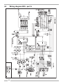
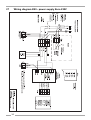
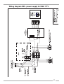
21 GB
R
ONE MORE TIME VINYL
Operating Instructions
1
Technical details OMT VINYL . . . . . . . . . . . . . . . . . . . . . . . . . . . . . . . . . . . . . . . . 3
1.1
Features . . . . . . . . . . . . . . . . . . . . . . . . . . . . . . . . . . . . . . . . . . . . . . . . . . . . . . . . . . . . . . . . . . . . . . . . . 3
1.2
Power supply . . . . . . . . . . . . . . . . . . . . . . . . . . . . . . . . . . . . . . . . . . . . . . . . . . . . . . . . . . . . . . . . . . . . . 3
1.3
Dimensions: . . . . . . . . . . . . . . . . . . . . . . . . . . . . . . . . . . . . . . . . . . . . . . . . . . . . . . . . . . . . . . . . . . . . . . 3
1.4
Optional . . . . . . . . . . . . . . . . . . . . . . . . . . . . . . . . . . . . . . . . . . . . . . . . . . . . . . . . . . . . . . . . . . . . . . . . . 3
2
Set up to play . . . . . . . . . . . . . . . . . . . . . . . . . . . . . . . . . . . . . . . . . . . . . . . . . . . . . 4
3
Component functions and adjustment . . . . . . . . . . . . . . . . . . . . . . . . . . . . . . . . . 4
3.1
Selection & Credit Computer (S&CC) . . . . . . . . . . . . . . . . . . . . . . . . . . . . . . . . . . . . . . . . . . . . . . . . . 4
3.2
3.2.1
3.2.2
3.2.3
Service programs . . . . . . . . . . . . . . . . . . . . . . . . . . . . . . . . . . . . . . . . . . . . . . . . . . . . . . . . . . . . . . . . .
How to call up service program . . . . . . . . . . . . . . . . . . . . . . . . . . . . . . . . . . . . . . . . . . . . . . . . . . . . . . . .
How to leave the service program . . . . . . . . . . . . . . . . . . . . . . . . . . . . . . . . . . . . . . . . . . . . . . . . . . . . . .
Memory ON/OFF . . . . . . . . . . . . . . . . . . . . . . . . . . . . . . . . . . . . . . . . . . . . . . . . . . . . . . . . . . . . . . . . . . .
3.3
Free play . . . . . . . . . . . . . . . . . . . . . . . . . . . . . . . . . . . . . . . . . . . . . . . . . . . . . . . . . . . . . . . . . . . . . . . . . 6
3.4
Playstimulator / continuous play . . . . . . . . . . . . . . . . . . . . . . . . . . . . . . . . . . . . . . . . . . . . . . . . . . . . . 7
3.5
Coin and credit programming . . . . . . . . . . . . . . . . . . . . . . . . . . . . . . . . . . . . . . . . . . . . . . . . . . . . . . . 8
4
Device description of the amplifier K99 . . . . . . . . . . . . . . . . . . . . . . . . . . . . . . . . 9
5
Technical data K99 . . . . . . . . . . . . . . . . . . . . . . . . . . . . . . . . . . . . . . . . . . . . . . . . . 9
6
Verification of power voltage. . . . . . . . . . . . . . . . . . . . . . . . . . . . . . . . . . . . . . . . 10
7
Position of fuses and plug connectors on the K99 . . . . . . . . . . . . . . . . . . . . . . 11
8
The first power ON . . . . . . . . . . . . . . . . . . . . . . . . . . . . . . . . . . . . . . . . . . . . . . . . 12
9
Volume control . . . . . . . . . . . . . . . . . . . . . . . . . . . . . . . . . . . . . . . . . . . . . . . . . . . 12
10
The infrared remote control . . . . . . . . . . . . . . . . . . . . . . . . . . . . . . . . . . . . . . . . . 13
11
Treble and bass control . . . . . . . . . . . . . . . . . . . . . . . . . . . . . . . . . . . . . . . . . . . . 14
12
Automatic volume correction . . . . . . . . . . . . . . . . . . . . . . . . . . . . . . . . . . . . . . . 14
13
Background Music - volume attenuation . . . . . . . . . . . . . . . . . . . . . . . . . . . . . . 14
14
External speaker connection . . . . . . . . . . . . . . . . . . . . . . . . . . . . . . . . . . . . . . . . 15
15
External amplifier connection . . . . . . . . . . . . . . . . . . . . . . . . . . . . . . . . . . . . . . . 16
16
Disabling the internal mute circuit . . . . . . . . . . . . . . . . . . . . . . . . . . . . . . . . . . . 17
17
Input selector . . . . . . . . . . . . . . . . . . . . . . . . . . . . . . . . . . . . . . . . . . . . . . . . . . . . 17
18
Trouble shooting chart. . . . . . . . . . . . . . . . . . . . . . . . . . . . . . . . . . . . . . . . . . . . . 18
18.1
Failures of the illumination, lamps and power system generally . . . . . . . . . . . . . . . . . . . . . . . . . . 18
18.2
Fuses of the power supply - which one controls what circuit . . . . . . . . . . . . . . . . . . . . . . . . . . . . 19
18.3
Faults with the coin and credit system . . . . . . . . . . . . . . . . . . . . . . . . . . . . . . . . . . . . . . . . . . . . . . . 20
18.4
Faults with the selection system (Credit system is working) . . . . . . . . . . . . . . . . . . . . . . . . . . . . . 21
18.5
Repetitive play of records, selected or non-selected ones . . . . . . . . . . . . . . . . . . . . . . . . . . . . . . . 22
18.6
Failures of the record changer after properly completed selection . . . . . . . . . . . . . . . . . . . . . . . . 22
18.7
Failures with the tone arm or the tone system . . . . . . . . . . . . . . . . . . . . . . . . . . . . . . . . . . . . . . . . . 24
OMT VINYL – edition: 13.08.2007
5
5
6
6
1
18.8
Record not properly returned to carrier . . . . . . . . . . . . . . . . . . . . . . . . . . . . . . . . . . . . . . . . . . . . . . 24
18.9
18.9.1
18.9.2
18.9.3
18.9.4
18.9.5
18.9.6
18.9.7
18.9.8
18.9.9
18.9.10
18.9.11
18.9.12
Notes . . . . . . . . . . . . . . . . . . . . . . . . . . . . . . . . . . . . . . . . . . . . . . . . . . . . . . . . . . . . . . . . . . . . . . . . . .
Note 1 . . . . . . . . . . . . . . . . . . . . . . . . . . . . . . . . . . . . . . . . . . . . . . . . . . . . . . . . . . . . . . . . . . . . . . . . . .
Note 2 . . . . . . . . . . . . . . . . . . . . . . . . . . . . . . . . . . . . . . . . . . . . . . . . . . . . . . . . . . . . . . . . . . . . . . . . . .
Note 3 A . . . . . . . . . . . . . . . . . . . . . . . . . . . . . . . . . . . . . . . . . . . . . . . . . . . . . . . . . . . . . . . . . . . . . . . .
Note 3 B . . . . . . . . . . . . . . . . . . . . . . . . . . . . . . . . . . . . . . . . . . . . . . . . . . . . . . . . . . . . . . . . . . . . . . . .
Note 3 C . . . . . . . . . . . . . . . . . . . . . . . . . . . . . . . . . . . . . . . . . . . . . . . . . . . . . . . . . . . . . . . . . . . . . . . .
Note 4 . . . . . . . . . . . . . . . . . . . . . . . . . . . . . . . . . . . . . . . . . . . . . . . . . . . . . . . . . . . . . . . . . . . . . . . . . .
Note 5 . . . . . . . . . . . . . . . . . . . . . . . . . . . . . . . . . . . . . . . . . . . . . . . . . . . . . . . . . . . . . . . . . . . . . . . . . .
Note 6 . . . . . . . . . . . . . . . . . . . . . . . . . . . . . . . . . . . . . . . . . . . . . . . . . . . . . . . . . . . . . . . . . . . . . . . . . .
Note 7 . . . . . . . . . . . . . . . . . . . . . . . . . . . . . . . . . . . . . . . . . . . . . . . . . . . . . . . . . . . . . . . . . . . . . . . . . .
Note 8 . . . . . . . . . . . . . . . . . . . . . . . . . . . . . . . . . . . . . . . . . . . . . . . . . . . . . . . . . . . . . . . . . . . . . . . . . .
Note 9 . . . . . . . . . . . . . . . . . . . . . . . . . . . . . . . . . . . . . . . . . . . . . . . . . . . . . . . . . . . . . . . . . . . . . . . . . .
Note 10 . . . . . . . . . . . . . . . . . . . . . . . . . . . . . . . . . . . . . . . . . . . . . . . . . . . . . . . . . . . . . . . . . . . . . . . . .
19
Connection diagram . . . . . . . . . . . . . . . . . . . . . . . . . . . . . . . . . . . . . . . . . . . . . . . 28
20
Circuit diagram OMT VINYL chassis . . . . . . . . . . . . . . . . . . . . . . . . . . . . . . . . . . 29
21
Wiring diagram K99 - power supply . . . . . . . . . . . . . . . . . . . . . . . . . . . . . . . . . . 30
22
Wiring diagram K99 - power amp. . . . . . . . . . . . . . . . . . . . . . . . . . . . . . . . . . . . . 31
23
Wiring diagram K99 - pre amp . . . . . . . . . . . . . . . . . . . . . . . . . . . . . . . . . . . . . . . 32
24
Wiring diagram K99 - sound controler . . . . . . . . . . . . . . . . . . . . . . . . . . . . . . . . 33
25
Wiring diagram K99 - port A . . . . . . . . . . . . . . . . . . . . . . . . . . . . . . . . . . . . . . . . . 34
26
Wiring diagram K99 - mute . . . . . . . . . . . . . . . . . . . . . . . . . . . . . . . . . . . . . . . . . . 35
27
Wiring diagram K99 - power supply Euro 230V . . . . . . . . . . . . . . . . . . . . . . . . . 36
28
Connection diagram IR remote control/amplifier K99 . . . . . . . . . . . . . . . . . . . . 38
2
25
25
25
25
26
26
26
26
26
27
27
27
27
OMT VINYL – edition: 13.08.2007
Features
1
Technical details OMT VINYL
1.1
Features
1.2
!
Stereo amplifier with automatic level control and electronic overload protection, power 2 x 55w
RMS
!
3 way stereo loudspeaker system with 6 speakers
!
100 selections (50 records) played by a high quality Tonar Magnetic System
!
Microprocessor controlling all functions including credit and bonus steps as well as record plays
and automatic memory of the top tunes
!
Playstimulator playing a record in intervals between 1 and 98 minutes automatically
!
An LED display presents playing record or credit available
!
Integrated volume control which can also be used as wired remote control
!
Connections for additional amplifier, external loudspeakers, microphone kit and output
transformer
Power supply
100 - 240v, 50/60cps
1.3
1.4
Dimensions:
Height
1520mm / 60.0inch
Width
815mm / 32.0inch
Depth
640mm / 25.25inch
Weight
157kg / 346lbs
Optional
!
Infrared remote control with selection buttons
!
Output transformer
!
Microphone kit
!
External speakers: Model LS 121
2 way speaker system, floor standing or wall mounting, cabinet with wooden pattern or black high
polish surface.
Dimensions:
Height 520mm / 20.5inch
Width 320mm / 12.6inch
Depth 250mm / 9.8inch
Musical power 120w, 8ohms
OMT VINYL – edition: 13.08.2007
3
Selection & Credit Computer (S&CC)
2
Set up to play
The ONE MORE TIME VINYL is delivered ready to play. There are several tasks to perform in order
to ensure proper operation and best sound.
1.
Open the jukebox. Apply slightly pressure against the door while turning the key. The lock is
spring loaded so the slight pressure against the door allows the key to turn easily.
2.
Remove the shipping bolts (M8x70) from the mechanism platform. There are two, one in the
rear right corner near the base of the tone arm, the other one in the front left corner near the
record carrier.
These bolts secure the platform during transport. Remove these bolts completely.
3.
Release the tie-down tone arm strap located at the base of the tone arm. This strap secures the
tone arm during transport. Check the cartridge and needle to insure proper position in the tone
arm.
4.
Place the records in the record carrier and title strips into the corresponding numerical slots in
the title strip holder. The holder can be removed completely from the machine to allow better
access by pushing the two locking springs left and right side slightly inwards.
To turn the record carrier, operate the lever marked ’rotate carrier’. The record carrier can be
turned in steps to achieve the best position for loading.
To step up credit, please use the credit button on the coin acceptor interface (Europe version) or
the credit button on the coin channel (US version).
" You should now be ready to enter a selection.
NOTE: Save the shipping guards and the tone arm strap. You will need them in case you decide to
move the jukebox to another location. Records should be taken out for transportation.
ATTENTION! Some parts of the electrical circuitary are connected to the power line (power
transformer, fluorescent tube, ballast and accociated wiring).
Never attempt any intervention to these parts unless qualified.
3
Component functions and adjustment
3.1
Selection & Credit Computer (S&CC)
The Selection and Credit Computer is the brain of the One More Time Vinyl. There are several
optional programs and programming features which can be very useful.
4
!
Service Program
This program allows to retrieve various information as well as concluding certain service checks
on the mechanism. All programs are communicated to the S&CC by means of the selection
buttons.
!
Free play
This allows free selection of multiple titles.
!
Playstimulator
The playstimulator plays a record automatically in intervals of 1 to 98 minutes.
OMT VINYL – edition: 13.08.2007
Service programs
3.2
Service programs
3.2.1
How to call up service program
2
Set slide switch ’SERVICE’ (1) to ’ON’.
Z
2.
T.T.
+2
+3
K
Press ’LT’ button (2) once.
Service
ON
OFF
GP
+
6
Korb
Location
F
6
5
4
3
2
0
GP
6
5
4
3
2
1
0
7
6
5
4
3
2
0
BS
B4
6
5
4
3
2
1
0
B3
6
5
4
3
2
1
0
B2
M
LT
1
2
4
5
T1
10
20
T
1.
1
+B
B1
ST1
ACHTUNG:
C
0047971
ST3
100 - 160 - 200
M3 M6 M
ST2
Selection &
Credit Computer
MEMORY-Stecker von OFF
auf ON umstecken, wenn
Top Tunes, Popularitätszähler
oder Kassenzähler arbeiten soll.
ATTENTION: Move MEMORY Plug from OFF
to ON if Top tunes, Pop Meter or
Cash Box Content Registration
is required.
ATTENTION: Placer la prise MEMORY en
position ON de la position OFF
si le Top Tunes, le compteur de
popularité et le contenu de la
caisse sont demandés.
ON
Memory
OFF
Button 0 - least popular titles (flops)
Pressing button 0 once indicates the least
popular record. Pressing button 0 again
shows the record with second lowest number
of plays. Press button 0 again shows the
third lowest etc..
Press button ’R’ (RESET) to terminate the
’flop’ call.
Button 1 - Top Tunes
Shows the record which was played most frequently followed by the number of plays (Max. 99). If
one record was played more often than 99 times, the counter remains in this position. Pressing
button 1 again shows the second popular record, etc.
Press button ’R’ RESET to terminate the ’Top Tune’ call.
Button 2 - cash box contents
Shows the cash box contents in basic units; basic units being the value of the lowest coin, resp. coin
value of coin output 1 on the S&CC.
Example (lowest coin 25ct):
display readout: 0 4 5 = 45 x 25ct = $ 11.25
Press button ’R’ RESET to terminate the ’cash box contents’ call.
Button 3 - clear memory
Press and hold down button 3, then press button ’R’ RESET. All counters are reset to zero.
Button 4 - display check and program number version
When you press button 4 the digital display automatically indicates the number 8 on all three digits.
Successivly ’Record Playing’, ’Hit of the House’, ’Error’ and ’Credit’ will light and the program version
number will appear, e.g. 7.01 or higher.
Button 5 - Playstimulator
The playstimulator is playing a random record automatically after a programmed time period. It is
programmable between 1 and 98 minutes. For programming please refer to chapter 3.4, on page 7.
OMT VINYL – edition: 13.08.2007
5
Free play
Button 6 - A-side solenoid
When you press button 6 the display shows 6 - 1, relay M6 of the S&CC and the A-side solenoid
should be activated while the display shows 6 - 2.
Button 7 - check of gear box motor
When you press button 7 relay M should be activated and the changer plays the B-side of the record.
Display shows 7 - 4.
After the record has been played, it will be returned into the carrier.
Button 8 - check of record carrier
When you press button 8 relay M3 is activated and the record carrier turns as long as button 8 is
pressed. The gripper arm must be in rest position. The display shows 8 - 0.
Button 9 - gripper arm position
Press button 9, test of the gripper arm position. Display shows 9 - 0 if the gripper arm is in rest
position, 9 - 1 if the gripper arm is in play position.
How to leave the service program
3.2.3
1.
Set slide switch ’SERVICE’ to ’OFF’.
1.
Press ’LT’ button. The record carrier turns to position 101.
Memory ON/OFF
Z
T.T.
+2
+3
K
ATTENTION! Statistic read outs
(service programs 0 - 2) are only
valid if the internal memory
battery is connected to Memory
ON (plug on upper pin) as
shown.
With Memory OFF (plug on lower
pin) counters are reset when the
jukebox is switched off.
Service
GP
ON
OFF
+
6
Korb
Location
F
6
5
4
3
2
0
GP
7
6
5
4
3
2
0
BS
6
5
4
3
2
1
0
B4
6
5
4
3
2
1
0
B3
6
5
4
3
2
1
0
B2
M
+B
B1
ST1
ACHTUNG:
ST3
100 - 160 - 200
M3 M6 M
ST2
Selection &
Credit Computer
MEMORY-Stecker von OFF
auf ON umstecken, wenn
Top Tunes, Popularitätszähler
oder Kassenzähler arbeiten soll.
ATTENTION: Move MEMORY Plug from OFF
to ON if Top tunes, Pop Meter or
Cash Box Content Registration
is required.
ATTENTION: Placer la prise MEMORY en
position ON de la position OFF
si le Top Tunes, le compteur de
popularité et le contenu de la
caisse sont demandés.
ON
Memory
OFF
C
0047971
3.3
LT
1
2
4
5
T1
10
20
T
3.2.2
Free play
Connect jumper wire on ’GP’ between
0 and F on the S&CC. Press ’LT’
button.
Free play now allows free selections.
T.T.
+2
+3
ON
OFF
GP
+
6
Korb
Location
6
F
6
5
4
3
2
0
GP
7
6
5
4
3
2
0
BS
6
5
4
3
2
1
0
B4
6
5
4
3
2
1
0
6
5
4
3
2
1
0
B3
B2
M
LT
B1
OMT VINYL – edition: 13.08.2007
Playstimulator / continuous play
3.4
Playstimulator / continuous play
The playstimulator may be programmed to random selection of a title in periods of 1 to 98 minutes.
(Factory preset is 99 for continuous play). Therefore:
1.
Call up service program (slide switch SERVICE in position ON, press ’LT’ button once).
2.
Press button 5.
3.
Press button 9, display shows 9 _ _.
4.
Enter number of minutes required for the interval between play
# 01 = 1 minute
# 02 = 2 minutes etc.
# 00 = playstimulator is switched OFF
# 99 = continuous play
5.
Press button ’R’ RESET.
6.
Set slide switch SERVICE to position OFF.
7.
Press ’LT’ button.
Z
T.T.
+2
+3
K
Service
ON
OFF
GP
+
6
Korb
Location
F
6
5
4
3
2
0
GP
7
6
5
4
3
2
0
BS
6
5
4
3
2
1
0
B4
6
5
4
3
2
1
0
B3
6
5
4
3
2
1
0
B2
M
LT
1
2
4
5
T1
10
20
T
NOTE: If the jukebox is equipped with
a continuous play switch, you only
have to set the slide switch to position
ON to activate the playstimulator/
continuous play.
+B
B1
Continuous
ST1
Play
on
ACHTUNG:
C
0047971
OMT VINYL – edition: 13.08.2007
ST3
100 - 160 - 200
M3 M6 M
off
ST2
Selection &
Credit Computer
MEMORY-Stecker von OFF
auf ON umstecken, wenn
Top Tunes, Popularitätszähler
oder Kassenzähler arbeiten soll.
ATTENTION: Move MEMORY Plug from OFF
to ON if Top tunes, Pop Meter or
Cash Box Content Registration
is required.
ATTENTION: Placer la prise MEMORY en
position ON de la position OFF
si le Top Tunes, le compteur de
popularité et le contenu de la
caisse sont demandés.
ON
Memory
OFF
7
Coin and credit programming
3.5
Coin and credit programming
The price per play is set by jumper wires on the S&CC as shown in the examples. After having
changed wire links press ’LT’ button to confirm new settings.
US (example)
$ 1.00
25cts
PRICE OF SELECTION
1 play for 50 cts
3 plays for $ 1.00
21 plays for $ 5.00
TT :
+2 :
+3 :
GP+6
Korb
Location
:
:
:
:
F
6
5
4
3
2
0
:
:
:
:
:
:
:
GP
Select 222 for 8 Top Ten
7
6
5
4
3
2
0
:
:
:
:
:
:
:
BS
:
:
:
:
:
:
:
:
:
:
:
:
:
:
6
5
4
3
2
1
0
B4
6
5
4
3
2
1
0
B3
:
:
:
:
:
:
:
6
5
4
3
2
1
0
B2
:
:
:
:
:
:
:
LT
B1
1
2
4
5
T1
10
20
^
+B
0,25 blue
1 $ grey
orange
yellow
white
brown
Coinco
mech.
Europe (example)
1,-
2,-
2 plays - 0,5
5 plays - 1,11 plays - 2,-
T.T.
+2
+3
GP
+6
:
:
:
:
:
:
:
Korb
Location
F
6
5
4
3
2
0
:
:
:
:
:
:
:
GP
7
6
5
4
3
2
0
:
:
:
:
:
:
:
BS
:
:
:
:
:
:
:
B4
:
:
:
:
:
:
:
6
5
4
3
2
1
0
B3
NRI
6
5
4
3
2
1
0
:
:
:
:
:
:
:
B2
6
5
4
3
2
1
0
:
:
:
:
:
:
:
B1
LT
1
2
4
5
T1
10
20
0,5
1,0
2,0
T
0,5
green
violet
+B
red.
brown
white
grey
Credit button
on interface
G13
8
OMT VINYL – edition: 13.08.2007
Coin and credit programming
4
Device description of the amplifier K99
The amplifier K99 is optimised for universal use in Deutsche Wurlitzer GmbH jukeboxes. Great
importance had been attached for an easy handling and stand alone function without the S&CC unit.
The output power is designed for the standard used internal speakers of Deutsche Wurlitzer GmbH
jukeboxes.
DETAILS:
Standard equipment:
!
Hybrid power stage technology, short circuit and over temperature protected
!
2 inputs (stereo): CD and tape
!
1 mono input for optional microphone kit
!
Volume control with 2 pots onboard
!
Volume control possible with pots and / or IR at the same time. The pot used at last determines
the volume.
!
The wired remote box is accessible from the machine rear wall with 2 volume control pots, cancel
and mute button (mute with toggle function).
!
Bass and treble control with pots
!
BGM volume reduction, controllable with pot
!
Automatic volume correction (AVC), switchable
!
2 channel operation switchable, RH = internal speakers, LH = external speakers
!
Status display with 7segment display
!
Independent controllable RCA output to connect external amplifiers
!
For use with the old and the new changer mechanism.
!
Optional:
5
!
Remote control with large distance range. Functions: track selection / volume chan. 1 / volume
chan. 2 / mute (toggle) / cancel
!
70v output transformer
!
Microphone kit
Technical data K99
General
USA / Canada
Supply
100v - 240v
117v
Mains frequency
50cps - 60cps
60cps
Input voltage CD
typ. 1.2v
typ. 1.2v
Input voltage tape
300mv
300mv
Output voltage pre amplifier
<=1veff
<=1veff
Output power
2 x 55w (rms)
2 x 55w (rms)
Output impedance
min. 4ohm
min. 4ohm
Transmission range
20cps - 20,000cps
20cps - 20,000cps
Distorsion factor
< 1%
< 1%
Noise level
Depending on the adjusted volume of the jukebox
noise levels of more than 70 dB(A) can be reached.
OMT VINYL – edition: 13.08.2007
9
Coin and credit programming
Verification of power voltage
The voltage settings are marked on
the cover plate of the mains
transformer. Machines for USA are
set to 117v. They have a special
transformer according to UL standard
which is not adjustable. Jukeboxes
“UNI-Pack” are shipped with 230v
setting. Mains voltage is indicated on
the label of the transformer cover. The
mains fuse (T3.15A/230v F6A/117v)
is located on the left bottom side inbetween the three terminals for the bill
acceptor, the external mains switch
and the fluorescent lamps.
Achtung
Vor A nahme
ziehen
er
appe
en Netzstecker
arning
Shock hazar
o
not open
Netzsicherung
Mains Fuse
Scheinannehmer 210-240V - T 4A
100-117V
- F 6A
Billacceptor
240
230
220
210
117
100
Netzspannung
50/60 Hz
Mains Voltage
50/60 cps
ur Beachtung Nur Sicherungen mit
gleicher r e
un gleichem
ert
erwen en, um Schä en zu ermei en
aution
To re uce the risk of fire
replace onl with same t p an rating fuses
Verstärker
Amplifier
6
Externer Hauptschalter
External Mains switch
Leuchtstofflampen
Fluorescent Lamps
230V / 117V
Netzsicherung/
Mains Fuse
210-240V - T3,15A
100-117V - F6A
Loosen the four screws to remove the
cover plate (small arrows) to get
access to the mains transformer.
ATTENTION! Always remove power plug before opening transformer cover plate. Never
attempt any intervention to these parts unless qualified!
The position of the two plug connectors on the transformer terminals 1 to 9 (primary side) indicates
the current voltage setting. The following combinations are possible:
240v = 1 - 9
230v = 1 - 8
220v = 2 - 9
210v = 2 - 8
117v = 1 - 6
100v = 2 - 6
bk
bl
NOTE: Never connect the fluorescent
supply to other contact.
1 - 8 = 230V
gy
If you intend to change the power
voltage to a higher voltage (e.g. from
117v to 230v) it is recommended to
use a subtransformer for the
fluorescent lamps or change the
ballast according to the used voltage
(e.g. for 230v).
10
br
1 2 3 4 5 6 7 8 9
fluorescent
lamps
Mains voltage-Netzspannung
240V = 1 - 9
230V = 1 - 8
220V = 2 - 9
210V = 2 - 8
117V = 1 - 6
100V = 2 - 6
Temperaturwächter
= 2- 4
thermalfuse
Deutsche Wurlitzer GmbH
Art.-Nr. 0058498 K99 210VA
VDE 0551/ EN 60742 50/60Hz
10 11 12 13 14 15 16 17 18
Notice that these settings cannot be
made
on
machines
produced
according to UL standard (US
version).
y/r
wt
bk
wt/r
mains
amplifier
OMT VINYL – edition: 13.08.2007
Coin and credit programming
Position of fuses and plug connectors on the K99
EXTRA EINGANG 300mV
EXTRA INPUT 300mV
L
R
Verstärker K 99
Amplifier K 99 C-UL
MECHANIK
MECHANISM
0056041
0058484
2RP04
T4A
Treble
BGM
EINGANG CD
INPUT CD
L
R
100-240 V 117 V
50Hz/60Hz 60Hz
ANZEIGE / DISPLAY
3,0 AMP
250 V AC
SLOW BLOW
30V~ 26V~ 26V~ 12V=
DC
AC
AC
AC
2-KANAL / 2-CHANNEL
2P12
Intern
Extern
Channel 1 Channel 2 Bass
MUTE
AVC
RS232
MICRO
BGM
ok.
SCHALTER / SWITCHES
AUTO 1 MUTE
NORMAL 2 RS232
STEREO
TAPE
RS 232
2LP04
2P04
STEREO
CAUTION
TO REDUCETHE RISK
OF FIRE REPLACE ONLY
WITH SAMETYPE AND
RATING FUSE
SICHERUNG
F1 - F4
FUSE
INFRAROT-REGLER
INFRARED-REMOTE
AUSGANG
OUTPUT
L
R
1P06A
1P06B
OPTION
MONO
AUS/OFF
SERVICE
SEPARATE 1 VOLUME PARALLEL
HIGH
AUS/OFF
STEREO
CD
INTERNER LAUTSPRECHER
INTERNAL SPEAKER
2
3
4
5
AVC
AVC
MODE
LOW
EIN/ON
2-KANAL/2CHANNEL
You will find the fuses behind the
1P04
amplifier cover plate. To remove
1P03
the plate first unplug the cable
coming from the mains transformer
D
A
R
C
and cable to the IR remote control.
Next lose slightly both nuts on top
of the amplifier accessible through
the holes in the cover plate
(arrows). To remove the plate first take the bottom side out of its hinges and then the top side.
CD-TRAFO
CD-TRANSFORMER
F1
F2
F3
F4
INPUT
AUS/OFF 6 BGM
TAPE
EIN/ON
ERWEITERUNG
EXTENSION
BUBBLE-TUBES
NETZTRAFO
TRANSFORMER
MIKROFON
MICROPHONE
1P09
BGM
The fuse holders on the amplifier
P.C.B. are capable to hold fuses of
6x32mm or 5x20mm size.
DECKEL ABNEHMEN
REMOVE COVER
OPTION
Fuses used on the amplifier board
are DIN41571 5x20 slow blow or
medium blow in the US version
6x32 slow blow.
Value of used fuses is printed on
the amplifier cover. Please replace
only with same type and rating
fuses.
L
R
EXTERNER LAUTSPRECHER
EXTERNAL SPEAKER
8W / 80 W
7
FERNREGLER
REMOTE-CONTROL
ECKEL BNEHMEN
EMOVE OVER
Connection plan of the plug terminals:
! 1P09
mechanism, SCC unit
! 1P06A option
! 1P06B RIAA decoder
! 2LP04 external speakers, LH
! 2P04
external speakers, ground
! 2RP04 external speakers, RH
! 2P12
Internal speakers
! 1P03
bubble tubes
Fuse
Failure
Main fuse T 3.15 resp. F6 A for 110/117 V.
No illumination, machine completely dead.
Fuse F1: T4A supply 30V ~
Credit circuit via LED M is interrupted. If credits are still in
memory or free play is programmed.
Fuse F2: T4A supply 26V ~
Fuse F3: T4A supply 26V ~
The colour tubes of the One More Time do not rotate, the
heating of the bubble tubes is off - no bubbles will appear.
Possibly defect of the power stage of the amplifier.
Fuse F4: T4A supply +12 V=
SCC unit dead - digital display dark (except red LED M still
lighting up on coin insertion). The LED’s K and Z on the SCC
unit are dark. No initialisations run after power ON. The
status display on the amplifier is dark.
OMT VINYL – edition: 13.08.2007
11
Coin and credit programming
The first power ON
EXTRA EINGANG 300mV
EXTRA INPUT 300mV
L
R
0056041
0058484
STEREO
Intern
AVC
S232
MICRO
MUTE
AVC
RS232
MICRO
30V~ 26V~ 26V~ 12V=
AC
AC
AC
DC
2-KANAL / 2-CHANNEL
TAPE
BGM
BGM
ok.
SCHALTER / SWITCHES
1
2
STEREO
ok.
1
INTERNER LAUTSPRECHER
INTERNAL SPEAKER
CD-TRAFO
CD-TRANSFORMER
TAPE
ANZEIGE / DISPLAY
3,0 AMP
250 V AC
SLOW BLOW
T4A
F1
F2
F3
F4
AUS/OFF
STEREO
CD
AUS/OFF
2
3
4
5
6
BGM
AVC
MODE
INPUT
BGM
EIN/ON
2-KANAL/2CHANNEL
TAPE
EIN/ON
ERWEITERUNG
EXTENSION
FERNREGLER
REMOTE-CONTROL
BUBBLE-TUBES
NETZTRAFO
TRANSFORMER
RS 232
100-240 V 117 V
50Hz/60Hz 60Hz
Treble
MUTE
USE
EINGANG CD
INPUT CD
L
R
Extern
Channel 1 Channel 2 Bass
MIKROFON
MICROPHONE
CAUTION
TO REDUCETHE RISK
OF FIRE REPLACE ONLY
WITH SAMETYPE AND
RATING FUSE
SICHERUNG
F1 - F4
F
INFRAROT-REGLER
INFRARED-REMOTE
AUSGANG
OUTPUT
L
R
OPTION
MONO
DECKEL ABNEHMEN
REMOVE COVER
Volume control
You can control the volume of the
jukebox from different points at the
same time:
Verstärker K 99
Amplifier K 99 C-UL
IR
With the pots of the control box at
the rear side of the jukebox.
OPTION
OPTION
TO REDUCETHE RISK
OF FIRE REPLACE ONLY
WITH SAMETYPE AND
RATING FUSE
SICHERUNG
F1 - F4
F
Intern
Extern
Channel 1 Channel 2 Bass
Treble
BGM
EINGANG CD
INPUT CD
L
R
available
STEREO
CAUTION
USE
100-240V 117 V
50Hz/60Hz 60Hz
T4A
ANZEIGE / DISPLAY
3,0 AMP
250 V AC
SLOW BLOW
MUTE
AVC
RS232
MICRO
30V~ 26V~ 26V~ 12V=
DC
AC
AC
AC
BGM
ok.
SCHALTER / SWITCHES
2-KANAL / 2-CHANNEL
AUTO 1 MUTE
NORMAL 2 RS232
STEREO
TAPE
RS 232
!
With an optional
remote control.
MONO
R
L
EXTERNER LAUTSPRECHER
EXTERNAL SPEAKER
8W / 80 W
!
With the pots Channel 1 and
Channel 2 on the amplifier.
AUS/OFF
SERVICE
SEPARATE 1 VOLUME PARALLEL
The device from which the volume is
changed determines it.
CD-TRAFO
CD-TRANSFORMER
HIGH 2
AUS/OFF 3
STEREO 4
CD 5
F1
F2
F3
F4
AVC
AVC
MODE
INPUT
AUS/OFF 6 BGM
LOW
EIN/ON
2-KANAL/2CHANNEL
TAPE
EIN/ON
ERWEITERUNG
EXTENSION
BUBBLE-TUBES
NETZTRAFO
TRANSFORMER
The volume control box can be taken
out and be used as a remote control.
Its cable may be extended as required
with any kind of wire. The voltages of the control wires are max. 5v DC.
BGM
INTERNER LAUTSPRECHER
INTERNAL SPEAKER
MIKROFON
MICROPHONE
MECHANIK
MECHANISM
!
EXTRA EINGANG 300mV
EXTRA INPUT 300mV
L
R
DECKEL ABNEHMEN
REMOVE COVER
INFRAROT-REGLER
INFRARED-REMOTE
AUSGANG
OUTPUT
L
R
9
Verstärker K 99
Amplifier K 99 C-UL
MECHANIK
MECHANISM
BGM
Up to approx. 1 sec. after power on
random segments of the status display
will light. Followed by displaying the
version number of the amplifier
software (1.0, or higher). Then the
bottom segment for “ok.” and the
upper segment for MUTE will light.
The amplifier is now in STANDBY
MODE. Depending on other enabled
options more segments may light as
well (e.g. AVC).
DECKEL ABNEHMEN
REMOVE COVER
OPTION
The mains switch is located at the rear
side of the jukebox. Wallboxes are
equipped with an external mains
switch accessible from the side. In
position ‘I’ jukebox and amplifier are
switched on.
L
R
EXTERNER LAUTSPRECHER
EXTERNAL SPEAKER
8W / 80 W
8
FERNREGLER
REMOTE-CONTROL
DECKEL ABNEHMEN
REMOVE COVER
The control box has two volume knobs (Intern / Channel 1 and Extern / Channel 2). In position
”Stereo” the knob “Intern / Channel 1” is effective for the internal speakers. The knob Extern /
Channel 2 is controlling the volume of the RCA outputs for an optional external amplifier. In DIP
switch position ”2 Channel”, channel1 (RH) and 2 (LH) are controlled separately.
ATTENTION! The pots Channel 1 and Channel 2 on the amplifier are not effective if the wire
control box is connected.
12
OMT VINYL – edition: 13.08.2007
Coin and credit programming
10
The infrared remote control
An infrared remote control is installed from factory
or can be delivered as conversion kit (part no.
0058809). If it has been installed the hand
transmitter is located in the cash box.
If credit is given or free play is programmed a
record can be selected with the buttons 0 to 9 and
R.
Double button functions as required in the service
programs (i.e. press button 5 -hold down- and
press button R), are impossible. For this you can
only use the keyboard of the jukebox.
You can control the volume by means of the
buttons + and -. In stereo mode the internal +/buttons control the volume of the internal speakers.
The external +/- buttons control the volume of the
K99 RCA jacks for an optional external amplifier. In
2-channel mode these buttons control the volume
of the external speakers connected to the amplifier.
RCS-K
No.: 0059745
SELECTION
1
2
3
OPTION
4
5
6
RESET
7
8
9
selection buttons
0
POWER
VOLUME
-
+
-
+
INTERN
CHANNEL 1
EXTERN
CHANNEL 2
CANCEL MUTE
music control buttons
battery type
LR03 (AAA)
The power-on volume level is always set by the
channel 1 and 2 pots on the amplifier or on the
external volume control box.
BATTERY:
IEC LR03
(AAA)
+
Batteries are included: 4 micro cells type LR03
(AAA).
To open the battery compartment move the cover
like shown in the picture.
+
+
+
position of
the batteries
Type and position of the batteries are also shown
in the drawing.
Part no. of the hand transmitter: 0059745.
OMT VINYL – edition: 13.08.2007
13
Coin and credit programming
Treble and bass control
Sound control can be made by the bass and
treble pots on the amplifier.
EXTRA EINGANG 300mV
EXTRA INPUT 300mV
L
R
DECKEL ABNEHMEN
REMOVE COVER
Verstärker K 99
Amplifier K 99 C-UL
MECHANIK
MECHANISM
Intern
100-240 V 117 V
50Hz/60Hz 60Hz
BGM
ANZEIGE / DISPLAY
3,0 AMP
250 V AC
SLOW BLOW
MUTE
AVC
RS232
MICRO
30V~ 26V~ 26V~ 12V=
AC
AC
AC
DC
TAPE
RS 232
T4A
Treble
EINGANG CD
INPUT CD
L
R
Extern
Channel 1 Channel 2 Bass
BGM
ok.
SCHALTER / SWITCHES
2-KANAL / 2-CHANNEL
AUTO 1 MUTE
NORMAL 2 RS232
STEREO
INFRAROT- REGLER
INFRARED-REMOTE
AUSGANG
OUTPUT
L
R
OPTION
L
R
EXTERNER LAUTSPRECHER
EXTERNAL SPEAKER
8W / 80 W
OPTION
MONO
STEREO
CAUTION
TO REDUCETHE RISK
OF FIRE REPLACE ONLY
WITH SAMETYPE AND
RATING FUSE
SICHERUNG
F1 - F4
FUSE
AUS/OFF
SERVICE
SEPARATE 1 VOLUME PARALLEL
CD-TRAFO
CD-TRANSFORMER
F1
F2
F3
HIGH 2 AVC
AUS/OFF 3 AVC
STEREO 4 MODE
CD 5 INPUT
AUS/OFF 6 BGM
F4
LOW
EIN/ON
2-KANAL/2CHANNEL
TAPE
EIN/ON
ERWEITERUNG
EXTENSION
BUBBLE-TUBES
NETZTRAFO
FERNREGLER
REMOTE-CONTROL
ERWEITERUNG
DECKEL ABNEHMEN
REMOVE COVER
TRANSFORMER
Automatic volume correction
You can enable the correction with the DIP switch “AVC”
(the 3rd switch of the 6 sw. group) on the amplifier board.
Factory preset is AVC disabled.
With the second DIP switch of the 6 sw. group you can
reduce the intensity of volume correction.
Treble
BGM
ANZEIGE / DISPLAY
MUTE
AVC
RS232
MICRO
TAPE
BGM
ok.
SCHALTER / SWITCHES
AUTO 1 MUTE
NORMAL 2 RS232
AUS/OFF
SERVICE
SEPARATE 1 VOLUME PARALLEL
HIGH
AUS/OFF
STEREO
CD
2
3
4
5
AVC
AVC
MODE
INPUT
AUS/OFF 6 BGM
LOW
EIN/ON
2-KANAL/2CHANNEL
TAPE
EIN/ON
ERWEITERUNG
EXTENSION
FERNREGLER
REMOTE-CONTROL
Background Music - volume attenuation
You can switch on “BGM” by means of the DIP switch
“BGM”. The RH bottom segment of the status display on
the amplifier indicates “BGM active”. You can adjust the
volume attenuation with the pot “BGM”, as long it is
active.
This function can be used to limit the maximum output
volume.
Intern
Extern
Channel 1 Channel 2 Bass
Treble
BGM
ANZEIGE / DISPLAY
MUTE
AVC
RS232
MICRO
TAPE
RS 232
Complete function is only available for CD models.
BGM
ok.
SCHALTER / SWITCHES
AUTO 1 MUTE
NORMAL 2 RS232
AUS/OFF
SERVICE
SEPARATE 1 VOLUME PARALLEL
HIGH
AUS/OFF
STEREO
CD
2
3
4
5
AVC
AVC
MODE
INPUT
AUS/OFF 6 BGM
LOW
EIN/ON
2-KANAL/2CHANNEL
TAPE
EIN/ON
ERWEITERUNG
EXTENSION
14
INFRAROT-REGLER
INFRARED-REMOTE
13
Intern
Extern
Channel 1 Channel 2 Bass
RS 232
The AVC sets records with different volume levels to an
equal level. The level of records with a high level will be
reduced; the level of low-levelled records will be
increased. This control works rather slow to save the
dynamic range of the track.
INFRAROT-REGLER
INFRARED-REMOTE
12
BGM
INTERNER LAUTSPRECHER
INTERNAL SPEAKER
MIKROFON
MICROPHONE
11
FERNREGLER
REMOTE-CONTROL
OMT VINYL – edition: 13.08.2007
Coin and credit programming
External speaker connection
The amplifier can operate in two
different modes. The normal operation
mode reproduces the music in normal
stereo sound. So external speakers
can be added to each channel.
Verstärker K 99
Amplifier K 99 C-UL
MECHANIK
MECHANISM
0056041
0058484
Intern
Treble
BGM
EINGANG CD
INPUT CD
L
R
Extern
Channel 1 Channel 2 Bass
USE
100-240 V 117 V
50Hz/60Hz 60Hz
T4A
ANZEIGE / DISPLAY
3,0 AMP
250 V AC
SLOW BLOW
30V~ 26V~ 26V~ 12V=
AC
AC
AC
DC
2-KANAL / 2-CHANNEL
TAPE
BGM
ok.
SCHALTER / SWITCHES
AUTO 1 MUTE
NORMAL 2 RS232
STEREO
1
MUTE
AVC
RS232
MICRO
RS 232
L
R
EXTERNER LAUTSPRECHER
EXTERNAL SPEAKER
8W / 80 W
The so-called 2-Channel mode uses
both stereo channels like separate
mono amplifiers so that the sound can
be reproduced in different rooms but
then in mono only.
STEREO
CAUTION
TO REDUCETHE RISK
OF FIRE REPLACE ONLY
WITH SAMETYPE AND
RATING FUSE
SICHERUNG
F1 - F4
F
INFRAROT-REGLER
INFRARED-REMOTE
AUSGANG
OUTPUT
L
R
OPTION
MONO
AUS/OFF
SERVICE
SEPARATE 1 VOLUME PARALLEL
The amplifier may not be loaded with
more than 4 ohms per channel (less
ohms means more load!). On an
overload it switches itself off. After a
certain cool down time it switches
itself on. So if you do not eliminate the
reason for the overload the amplifier
produces continuously volume dropouts.
3
CD-TRAFO
CD-TRANSFORMER
F1
F2
F3
F4
HIGH
AUS/OFF
STEREO
CD
2
3
4
5
AVC
AVC
MODE
INPUT
AUS/OFF 6 BGM
LOW
EIN/ON
2-KANAL/2CHANNEL
TAPE
EIN/ON
ERWEITERUNG
EXTENSION
BUBBLE-TUBES
NETZTRAFO
TRANSFORMER
BGM
INTERNER LAUTSPRECHER
INTERNAL SPEAKER
MIKROFON
MICROPHONE
4
EXTRA EINGANG 300mV
EXTRA INPUT 300mV
L
R
DECKEL ABNEHMEN
REMOVE COVER
OPTION
14
FERNREGLER
REMOTE-CONTROL
2
DECKEL ABNEHMEN
REMOVE COVER
Position of the Stereo - Mono DIP switch (1), the
mode switch (2), the stereo - 2 channel switch (3)
and external speaker terminals (4).
The impedance of all external speakers per channel in ”Stereo” mode should not be less than 8
ohms, because the internal speakers represent a load of already 8 ohms per channel. If the amplifier
is operating in 2-Channel mode, the internal speakers are all connected to the RH channel (Channel
1); the LH channel (Channel 2) now applying to the screw terminals ”Externer Lautsprecher External speakers” may be loaded with max. 4 ohms.
The output power of the amplifier is approx. 55 watts (rms on max. 1% dist.) on a 4 ohms speaker
per channel, 18 watts to a 12 ohms speaker and approx. 9 watts to a 24 ohms speaker. That means,
that e.g., a 12 ohms speaker connected to the external channel at Dual Channel operation must be a
type of at least 18 Watts, otherwise the speaker is in danger of destruction at higher volumes. Note
that speaker groups like in hi-fi boxes may have, at certain frequencies, impedance much lower than
their rating. Make sure that all speakers are connected in correct polarity.
OMT VINYL – edition: 13.08.2007
15
Coin and credit programming
NOTE: Connect external speakers to the screw terminals on the LH amplifier in 2-Channel mode
only!
1
CD-TRAFO
CD-TRANSFORMER
2
AUS/OFF 3 AVC
EIN/ON
STEREO 4 MODE 2-KANAL/2CHANNEL
F1
F2
F3
F4
CD 5 INPUT T APE
AUS/OFF 6 BGM
EIN/ON
ERWEITERUNG
EXTENSION
BUBBLE-TUBES
NETZTRAFO
TRANSFORMER
+
Shock hazard!
Do not open!
Netzsicherung
Mains Fuse
Scheinannehmer 210-240V - T 4A
100-117V - F 6A
Billacceptor
4Ω
EINGANG CD
INPUT CD
L
R
OPTION
OPTION
F1
F2
F3
CD 5 INPUT T APE
AUS/OFF 6 BGM
EIN/ON
F4
+
ERWEITERUNG
EXTENSION
FERNREGLER
REMOTE-CONTROL
4Ω
DECKEL ABNEHMEN
REMOVE COVER
Achtung!
240
230
220
210
117
100
Warning!
Shock hazard!
+
Do not open!
Netzsicherung
Mains Fuse
Scheinannehmer 210-240V - T 4A
100-117V - F 6A
Billacceptor
Netzspannung
50/60 Hz
Mains Voltage
50/60 cps
Zur Beachtung: Nur Sicherungen mit
gleicher Größe und gleichem Wert
verwenden, um Schäden zu vermeiden.
Caution: To reduce the risk of fire
replace only with same typ and rating fuses.
Externer Hauptschalter
External Mains switch
Externer Hauptschalter
External Mains switch
Leuchtstofflampen
Fluorescent Lamps
230V / 117V
Leuchtstofflampen
Fluorescent Lamps
230V / 117V
In Stereo mode do not connect a single
speaker with less than 8ohm to each
channel.
+
Two speakers of 4ohm (serie) also
represent total impedance of 8ohm.
External amplifier connection
0056041
0058484
STEREO
Intern
Extern
Channel 1 Channel 2 Bass
Treble
BGM
EINGANG CD
INPUT CD
L
R
USE
100-240 V 117 V
50Hz/60Hz 60Hz
ANZEIGE / DISPLAY
3,0 AMP
250 V AC
SLOW BLOW
30V~ 26V~ 26V~ 12V=
DC
AC
AC
AC
2-KANAL / 2-CHANNEL
MUTE
AVC
RS232
MICRO
BGM
ok.
SCHALTER / SWITCHES
AUTO 1 MUTE
NORMAL 2 RS232
STEREO
TAPE
RS 232
T4A
AUS/OFF
SERVICE
SEPARATE 1 VOLUME PARALLEL
F1
F2
F3
F4
HIGH 2 AVC
AUS/OFF 3 AVC
STEREO 4 MODE
CD 5 INPUT
AUS/OFF 6 BGM
LOW
EIN/ON
2-KANAL/2CHANNEL
TAPE
EIN/ON
ERWEITERUNG
EXTENSION
BUBBLE-TUBES
NETZTRAFO
TRANSFORMER
BGM
INTERNER LAUTSPRECHER
INTERNAL SPEAKER
MIKROFON
MICROPHONE
CAUTION
TO REDUCETHE RISK
OF FIRE REPLACE ONLY
WITH SAMETYPE AND
RATING FUSE
SICHERUNG
F1 - F4
F
INFRAROT-REGLER
INFRARED-REMOTE
AUSGANG
OUTPUT
L
R
OPTION
MONO
CD-TRAFO
CD-TRANSFORMER
Connecting an external amplifier in 2channel mode is not useful.
Verstärker K 99
Amplifier K 99 C-UL
MECHANIK
MECHANISM
EXTRA EINGANG 300mV
EXTRA INPUT 300mV
L
R
DECKEL ABNEHMEN
REMOVE COVER
OPTION
The RCA terminals “Ausgang Output” can be connected to a line
input of an external amplifier. In
Stereo mode the output level is
normally controlled by means of the
pot for the 2nd channel. Alternatively
you can set the first DIP switch (1) to
ON to couple this output to the normal
volume control knobs (1st channel), so
that both amplifiers can be controlled
together.
L
R
EXTERNER LAUTSPRECHER
EXTERNAL SPEAKER
8W / 80 W
15
1
Vor Abnahme der Kappe den Netzstecker
ziehen!
Mains Voltage
50/60 cps
Caution: To reduce the risk of fire
replace only with same typ and rating fuses.
2
NETZTRAFO
TRANSFORMER
Netzspannung
50/60 Hz
Zur Beachtung: Nur Sicherungen mit
gleicher Größe und gleichem Wert
verwenden, um Schäden zu vermeiden.
1
2
AUS/OFF 3 AVC
EIN/ON
STEREO 4 MODE 2-KANAL/2CHANNEL
BUBBLE-TUBES
DECKEL ABNEHMEN
REMOVE COVER
240
230
220
210
117
100
TAPE
BGM
ok.
SCHALTER / SWITCHES
STEREO
CD-TRAFO
CD-TRANSFORMER
FERNREGLER
REMOTE-CONTROL
Verstärker
Amplifier
Warning!
AVC
RS232
MICRO
2-KANAL / 2-CHANNEL
INTERNER LAUTSPRECHER
INTERNAL SPEAKER
Achtung!
Vor Abnahme der Kappe den Netzstecker
ziehen!
ANZEIGE / DISPLAY
MUTE
3,0 AMP
250 V AC
SLOW BLOW
T4A
30V~ 26V~ 26V~ 12V=
AC
AC
AC
DC
RS 232
+
MIKROFON
MICROPHONE
+
4Ω
BGM
USE
100-240V 117 V
50Hz/60Hz 60Hz
INFRAROT-REGLER
INFRARED-REMOTE
AUSGANG
OUTPUT
L
R
1
Treble
BGM
TAPE
BGM
ok.
SCHALTER / SWITCHES
2
INTERNER LAUTSPRECHER
INTERNAL SPEAKER
+
Intern
Extern
Channel 1 Channel 2 Bass
Verstärker
Amplifier
AVC
RS232
MICRO
STEREO
0056041
0058484
STEREO
CAUTION
TO REDUCETHE RISK
OF FIRE REPLACE ONLY
WITH SAMETYPE AND
RATING FUSE
SICHERUNG
F1 - F4
F
L
R
EXTERNER LAUTSPRECHER
EXTERNAL SPEAKER
8W / 80 W
EXTRA EINGANG 300mV
EXTRA INPUT 300mV
L
R
ANZEIGE / DISPLAY
MUTE
3,0 AMP
250 V AC
SLOW BLOW
30V~ 26V~ 26V~ 12V=
AC
AC
AC
DC
2-KANAL / 2-CHANNEL
Verstärker K 99
Amplifier K 99 C-UL
MONO
BGM
RS 232
T4A
Treble
EINGANG CD
INPUT CD
L
R
100-240 V 117 V
50Hz/60Hz 60Hz
4Ω
8Ω
MIKROFON
MICROPHONE
OPTION
Intern
Extern
Channel 1 Channel 2 Bass
INFRAROT-REGLER
INFRARED-REMOTE
AUSGANG
OUTPUT
L
R
+
OPTION
+
STEREO
CAUTION
TO REDUCETHE RISK
OF FIRE REPLACE ONLY
WITH SAMETYPE AND
RATING FUSE
SICHERUNG
F1 - F4
FUSE
MECHANIK
MECHANISM
BGM
+
0056041
0058484
MONO
L
R
EXTERNER LAUTSPRECHER
EXTERNAL SPEAKER
8W / 80 W
8Ω
Verstärker K 99
Amplifier K 99 C-UL
EXTRA EINGANG 300mV
EXTRA INPUT 300mV
L
R
DECKEL ABNEHMEN
REMOVE COVER
DECKEL ABNEHMEN
REMOVE COVER
MECHANIK
MECHANISM
FERNREGLER
REMOTE-CONTROL
DECKEL ABNEHMEN
REMOVE COVER
To avoid hum- (earth-) loops try to use
an external amplifier with ground lift; it has no earth contacts. If it is impossible (e.g. receivers with
cable supply) you can separate both amps by means of the ground isolator part no. 0053300.
The signal of the RCA terminals is also controlled by the settings of bass, treble, BGM, AVC and
Mute.
16
OMT VINYL – edition: 13.08.2007
Coin and credit programming
16
Disabling the internal mute circuit
With the optional BGM-Connector (part
no. 0048130) you can connect an
external source to the jukebox with
automatic switch over. In this case the
amplifier should not be muted during
standby of the jukebox.
To reach this disable the internal mute
circuit by setting the first DIP switch (1)
“Mute” to OFF.
ANZEIGE / DISPLAY
MUTE
AVC
RS232
MICRO
TAPE
BGM
ok.
SCHALTER / SWITCHES
AUTO 1 MUTE
NORMAL 2 RS232
AUS/OFF
SERVICE
SEPARATE 1 VOLUME PARALLEL
For more information about the BGM
connector please order the Deutsche
Wurlitzer GmbH technical information
leaflets TI-MA-116.
17
HIGH
AUS/OFF
STEREO
CD
2
3
4
5
AVC
AVC
MODE
INPUT
AUS/OFF 6 BGM
LOW
EIN/ON
2-KANAL/2CHANNEL
TAPE
EIN/ON
ERWEITERUNG
Input selector
With DIP switch (1) you can set either CD
or tape input as active.
ANZEIGE / DISPLAY
MUTE
AVC
RS232
MICRO
TAPE
BGM
ok.
SCHALTER / SWITCHES
AUTO 1 MUTE
NORMAL 2 RS232
AUS/OFF
SERVICE
SEPARATE 1 VOLUME PARALLEL
HIGH
AUS/OFF
STEREO
CD
2
3
4
5
AVC
AVC
MODE
INPUT
AUS/OFF 6 BGM
LOW
EIN/ON
2-KANAL/2CHANNEL
TAPE
EIN/ON
ERWEITERUNG
EXTENSION
OMT VINYL – edition: 13.08.2007
17
Failures of the illumination, lamps and power system generally
18
Trouble shooting chart
18.1
Failures of the illumination, lamps and power system generally
Symptom
! No light, jukebox not working
at all
!
Fluorescent tubes do not light,
jukebox working
Cause
! No power at wall socket
! Open primary circuit
!
defective circuit, refer to
chapter 18.9.1, on page 25
Possible faults
! House fuse blown.
! Mains switch off or defective.
! Fuse of the jukebox Si1 blown, refer to
chapter 18.2, on page 19
! Defective power cord or plug
!
!
!
!
One or more of the lights of
the display do not light up,
jukebox working
!
Lamps’ circuit open
!
!
!
!
!
All lights of the display are
dark, jukebox working
!
Supply or common return of
lamps’ circuit open
!
!
!
!
!
Bulb defective
Defective lamp socket
Defective plug BROWN or its wiring
resp.
Defect inside the S&CC, e.g. lamp
driver transistor
Plug to the digital lights
Wire +30v broken (plug BROWN, pole
6, white line)
External short in lamps circuit has
tripped T5 (inside S&CC), this disables
IC14 to protect lamp driver transistors
Lamps of too high current rating
No 30VAC S&CC supply via pole 1,
plug RED, 30v rectifier D7 defective
(this, however, disables the coin
acceptance also)
!
Digital display remains dark,
jukebox working
!
Display signal circuit
interrupted
!
14-pole D.I.L. plug not in place or wrong
way round
!
Digital display shows nonsens
figures
!
Signal lines interchanged
!
14-pole D.I.L. plug to display displaced
not in line with base
S&CC defective, e.g. IC23
!
!
Digital display shows
incomplete figures (missing
segment)
The fault is the same with all
three digits.
!
Signal for one (or more)
segments missing
!
!
!
!
!
!
Digital display shows
incomplete figures (missing
segment)
The fault, however, occurs
with one of the three digits
only
!
One of the digits of the display
completely off
!
Segment signal does not
reach this digit
!
Multiplex signal missing
!
!
!
!
18
Lamps circuit plug not in light socket at
amplifier
Tube not properly seated in holder
Defective starter, defective tube
One (or more) of 14-pole plug(s) broken
off
One (or more) wire(s) of flat cable
broken
Broken connection at display PC-board
S&CC defective, e.g. IC23
Cracked conductor on display PC-board
Defective display unit (3 identical onedigit units)
Defective plug to display or broken wire
(A1, A2, A3)
S&CC defective (T6, T7, T8)
Defective display element
OMT VINYL – edition: 13.08.2007
Fuses of the power supply - which one controls what circuit
18.2
Fuses of the power supply - which one controls what circuit
The fuse holders on all boards are captable to hold either 5x20mm fuses of DIN41571 standard or
fuses of 6x32mm size.
The mains fuse holder will hold either 5x20 or 6x32mm fuse depending on the screw cap used.
ATTENTION!
Please replace fuses only with same type and rating!
Symptoms, if blown
!
Mains fuse
!
(in-screw cap holder in chassis
pan apron) T 3.15 (F6.3 in U.S.
version)
!
No illumination, jukebox completely
dead
!
Fuse F2 or F3
!
30v negative supply
!
Amplifier distorting on both channels,
green LED 1 not lit
With the changer, solenoid M3
(carrier latch) and M6 (a-side) not
working
!
!
Fuse F2 or F3
!
30v positive supply
!
!
Amplifier silent
Gear motor not working
!
Fuse F4
!
12v positive supply
!
S&CC dead (except red LED-M still
lighting up on coin insertion)
!
Fuse F1
!
30v AC supply
!
Record carrier motor and turntable
motor PM both not working
S&CC not registering coins (red
LED-M not lighting up)
!
!
Fuses on interface front door
OMT VINYL – edition: 13.08.2007
!
25v AC supply
!
Both rotating cylinders not turning,
bubble tubes not heating, lamp in
grill not lighting
19
Faults with the coin and credit system
18.3
Faults with the coin and credit system
The jukebox, however, normally operates with credits established with the Free Credit button
(located above the coin switches) resp. on the coin acceptor interface or by inserting coins.
The function of the coin system can be checked by observing the LED ’M’ at the S&CC, which
should light up with every coin accepted as well as every time Free Credit button is actuated.
Symptom
!
All coins are rejected
Cause
!
Disabled coin acceptor
Possible faults
!
!
!
!
!
Wrong credits (or none) with
one type of coin
!
!
Coin actuates the wrong coin
switch (US version)
Coin pulse does not reach the
S&CC
!
!
!
!
Permanent credit, display
shows 01 permanently, free
selections
!
Jumper is set from 0 to F (free
play)
!
Play prices not according to
installed label
!
Programming mistake
!
!
!
!
!
!
20
No credit although coins are
properly accepted
Free play, with GP jumper 0-F
still possible
!
No credit although coins are
registered (LED-M lights up)
Even no free play credit with
GP jumper set 0 to F
!
All coin input lines disabled
(LED does not light up)
!
!
S&CC out of operation
!
!
Missing power supply (green LED on
interface is OFF)
Dirt, oil, an odd article in the rejector,
rejector maladjusted or defective
Binding reject rod assembly holding
rejector gate open
Rejector or entire jukebox not leveled
Slug rejector not properly positioned,
leading the coin into the wrong switch
paddle or bypassing it (US version)
One line of the Coin-Switches-to-S&CC
cable broken, disconnected at either
end or wrongly set at S&CC connector
S&CC defective (IC17 - IC19, diodes
D14 - D24)
Wire jumper not in right position, refer to
the examples
Programming jumper making poor
contact (such can change pricing only
after the unit had been switched off or
the ’LT’ button had been actuated
Connect coin input lines to S&CC
according to credit programming see
chapt. 3.5 on page 8.
S&CC defective (e.g. diode 1
interrupted)
No power supplied to the S&CC, check
fuse F4, see also chapter 18.2, on page
19
S&CC defective
OMT VINYL – edition: 13.08.2007
Faults with the selection system (Credit system is working)
18.4
Faults with the selection system (Credit system is working)
Symptom
!
!
!
Cause
No selections, number of
actuated keys not displayed
(credits available)
!
No selections. After insertion
of coins a number appears in
the LH (hundreds) digit, but
selection keys are disabled.
With insertion of further coins
credits are displayed properly.
!
No response from one (or
more) key(s)
!
Open or shorted circuits in the
keyboard wiring
Possible faults
!
!
Permanent signal from the
selection key which number
appears in the dsiplay
!
Open circuit with this key(s)
!
!
!
!
!
!
The record played is not the
one selected. The selection
was properly displayed, and
the ’RECORD PLAYING’
display is the same
!
Improper counting of the
record carriers’ position
!
!
!
!
!
The record played is not the
one selected. The selection
was properly displayed, and
the ’RECORD PLAYING’
display is showing the actually
playing record
!
The selected record will not
be played. Instead the record
carrier rotates contiuously,
however, it stops if ’BLUE’
plug is pulled at the S&CC
!
OMT VINYL – edition: 13.08.2007
Record carrier does not stop
in the correct porsition
!
!
!
Light gate signal Z (counting)
or K (carrier position 1) or
both missing
!
!
!
Plug YELLOW displaced or not deep
enough inserted
Key RESET permanently closed or
shortened to ground (pole 12, brown,
plug YELLOW)
Jammed key, permanently closed key
contact
Wire of this key shortened to ground
Malfunction of the key contact
Broken wire to keyboard
Plug YELLOW not correctly seated
S&CC defective
Wrong adjustment of light control gates
(refer to chapter 18.9.3 and chapter
18.9.4, on page 26)
Interference pulses counted as carrier
pulses
Illumination light affecting the Z light
gate, reflections at the edges of carrier
base plate
Record carrier latch delayed by
mechanical friction
Record carrier latch too wide (latching
to late)
Light control gate Z retarded, refer to
chapter 18.9.3 and chapter 18.9.4, on
page 26 for proper adjustment
Lamp of light gate defective
Broken line in the wire to plug BLACK
See notes of chapter 18.9.3 and
chapter 18.9.4, on page 26
21
Repetitive play of records, selected or non-selected ones
18.5
Repetitive play of records, selected or non-selected ones
Symptom
!
!
Cause
Repetitive play of one record
with the record carrier not
making a rotation between
plays. This continues even if
’BLUE’ plug is disconnected at
the S&CC.
!
Repetitive play of one record,
discontinued after plug ’BLUE’
is pulled at the S&CC
!
Main cam motor not stopping
at the end of the play cycle
Possible faults
!
!
S&CC running out of program
!
!
!
Gripper moves a record
continuously (without having
the record actually played)
!
Motor MM has a permanent
ground return
!
!
!
18.6
Braking resistor R10 (47ohms) at motor
MM open
Wiper switch K6 maladjusted
S&CC out of program routine, possibly
caused by an interference pulse (cut
power to the S&CC for a restart of
program)
S&CC defective
Line blue to pole 2 of plug ’BLUE’
shorted to ground
Wiper K6 shorted to ground
S&CC defective (Relay 2-Mpermanently on, pull plug ’BLUE’ to test
this. Try service program, button 7 and
observe relay 2 through hole M)
Failures of the record changer after properly completed selection
Symptom
!
!
!
!
!
!
Cause
Possible faults
Record carrier continuously
rotating, even after plug
’BLUE’ is pulled.
If a selection is made the
carrier will be jammed when
the gripper arm tries to grip a
record
!
Stop pawl arm permanently
open
!
Carrier latch or its solenoid jammed
Record carrier continuously
rotating
If a selection is made the
record played is one placed
about 10 compartments
behind the selected one
!
Stop pawl arm solenoid
permanently switched on
!
Grey line from M3 to pole 4 of plug
’BLUE’ shorted to ground (= fault does
persist if plug ’BLUE’ is pulled)
Relay 4 of the S&CC jammed or
permanently switched on (= carrier
stops as soon as plug ’BLUE’ is pulled)
Carrier does not start after a
properly completed selection
Stop pawl arm does not open
!
!
Stop pawl arm not activated
!
!
!
!
22
DC supply -30v missing (fuse F2 or F3)
Coil of latch solenoid M3 open
Grey line from M3 to pole 4 or green
line to pole 1 (relays common), plug
’BLUE’ interrupted
S&CC defective. Go to service program,
key 8, to check relay 2 -M3-. Test
machine with a programming jumper
from pole 1 (green) to pole 4 (grey)
(refer to chapter 18.9.12, on page 27)
OMT VINYL – edition: 13.08.2007
Failures of the record changer after properly completed selection
!
Record carrier does not rotate
although the carrier latch
opens after a selection
!
Carrier motor KM disabled
!
!
!
!
!
A-side selections (odd
numbers) are not played but
the B-side of selected record
is played instead
!
Gripper arm does not move to
take the record out of the
carrier although the carrier
has stopped at the correct
position. After approx. 3
seconds the carrier moves to
the next selection if further
selections have been made
!
M6 shift solenoid and/or shift
rod not working
!
!
Main cam motor MM does not
start
!
!
!
!
Tone arm not moving to play
record, selected record was
properly brought to the
turntable
!
!
Main cam motor MM switched
off too early
Mechanical fault with the tone
arms’ tracking linkage
!
!
!
!
Turntable does not rotate,
record to be played is properly
brought to the turntable
!
Turntable motor PM disabled,
transmission disabled
!
!
!
!
!
Record on turntable returned
to carrier before play has
commenced
!
Main cam motor MM not
resting when system is in play
position
!
!
!
OMT VINYL – edition: 13.08.2007
Microswitch M3 (at carrier latch)
maladjusted or defective)
Microswitch K8 (at gripper arm)
maladjusted or gripper arm not full in
rest position (refer to chapter 18.9.6, on
page 26)
Defective motor KM, broken wiring
M6 coil open, M6 circuit open (refer to
chapter 18.9.7, on page 26)
Pole 3 (violet wire) of plug ’BLUE’ not
making contact. To check this, plull plug
’BLUE’ and insert a jumper wire
(programming jumper of the S&CC)
from pole 1 (green) to pole 3 (violet). If
M6 is energized now, the fault is inside
the S&CC (e.g. relay 3 -M6- is not
working)
Motor MM defective, resistor R15
(18ohms) open, no DC +30v to the
motor (fuse Si4), interruption with the
blue line from amplifier to motor
Short within the motor or with capacitor
C5 (in these cases R15 gets rather hot!)
Pull plug ’BLUE’ and set a jumper from
pole 1 (green) to pole 2 (blue): if motor
MM runs, the fault is within the S&CC
Relay 2 -MM- not working: go to service
program and test with key 7
Wiper switch K6 defective or
maladjusted (refer to chapter 18.9.9, on
page 27)
Tone arm loose on shaft (two worm
screws M3x4)
Linkage to tone arm control cam broken
Transmission O-ring from motor to
turntable broken or fallen off
Pulley freewheeling on motor shaft
(worm screw M3x4)
Microswitch K8 not making contact after
being released by record clamp
Defective turntable motor, open phase
shift capacitor C18
Cancel button at amplifier jammed in
’cancel’ position, same with cancel
button of a remote control, shorted
remote control cable
Tone arm trip switch K3 defective
(jammed in trip position)
Resistor R10 at motor MM open (refer
to chapter 18.9.6, on page 26)
23
Failures with the tone arm or the tone system
18.7
Failures with the tone arm or the tone system
Symptom
Cause
Possible faults
!
First second of music missing
because pick-up jumps off
starting groove
!
Tone arm release lever and
bushing assembly opening too
late
!
Tone arm release adjusting screw not
far enough in
!
Starting point of pick-up
floating (varies from record to
record)
!
Tone arm release lever and
bushing assembly opening too
early or tone arm loose on
shaft
!
Tone arm release adjusting screw not
far enough in. 2 worm screws M3x4 not
tight
!
Record not played completely
- tone arm lifts off too early
!
Main cam motor restarted too
early by tone arm trip switch
K3
!
Tone arm trip switch K3 maladjusted.
Remove adjusting screw to have play
time extended
!
Record playing but no sound
from the speakers
!
Defect in the system pick-up amplifier - speakers
!
Pick-up connector or speaker plug not
set at amplifier
Fuse Si4 open (= +30vDC missing.
This, however, would also disable motor
MM)
Grey line (pole) of amplifier-to-changer
cable broken off wiper K1 but shorted to
ground
!
!
18.8
Record not properly returned to carrier
Symptom
Cause
!
Gripper arm does not move to
take the record home
!
Main cam motor MM not
starting
!
Tone arm trip switch K3 not making,
maladjusted or open circuited. Refer to
chapter 18.7, on page 24 for faults if
symptom could have developed while a
record was playing
!
Retuned record not properly
unclamped (not freed) in the
carrier
!
Main cam motor MM switched
off too early
!
Wiper switch K6 wrongly adjusted
(compare with symptom 4 in chapter
18.6, on page 22 and chapter 18.9.6,
on page 26.
!
Record missing in
compartment is found in other
compartment or somewhere
about the chassis
!
Gripper arm delayed and
retarded by record binding
with the turntable (refer to
chapter 18.9.11, on page 27)
Gripper arm generally moving
too fast
!
Maladjusted turntable chassis linkage
Burr at the turntable pilot or at the
records’ centerring hole
Series resistor R15 (with motor MM)
shorted
!
24
Possible faults
!
!
OMT VINYL – edition: 13.08.2007
Notes
18.9
Notes
18.9.1
Note 1
The fluorescent lamps’ circuit is based on 230v. Except with certain ’UL’ models, there are always
230v at the lamps’ socket on the amplifier panel independent to the factory set mains voltage! Lamp,
starter and ballast is a matched group, never use replacements of other wattage! Check for a
defective starter before you check for a defective lamp.
18.9.2
Note 2
Some actual low tension power readings (averages). Numbers left of/are effective (R.M.S.) values,
read with a moving iron instrument. Numbers right of/are mean integrated values, read with a
moving coil instrument.
Changer &
S&CC idling
Record carrier
searching
Gripper arm
towards A-side
title*
Gripper arm
towards B-side
title*
Record playing
at minimum
volume
-30v
33.0 / 31.5
29.7 / 27.5
31.0 / 29.5
33.0 / 30.5
33.0 / 28.5**
+30v
33.0 / 31.5
30.5 / 29.5
31.5 / 29.0
32.0 / 30.0
33.0 / 28.5**
+12v, read at
fuse F4
10.0 / 12.5
9.5 / 11.5
10.0 / 12.0
10.0 / 12.0
10.0 / 12.0
30v AC, read at
fuse F1
31.5 / 29.5
29.5 / 27.5
31.0 / 29.5
31.0 / 29.5
31.5 / 29.5
All readings rounded for nearest full or half volt.
* Readings made while gripper arm is on the way from carrier towards turntable.
** At full volume these readings are around 1 volt lower.
Voltage readings directly at the S&CC against its chassis
18.9.3
Plug BROWN
pin 6 (brown)
+40v DC
voltage to indicator lamps
Plug RED
pin 1 (black)
30v AC
supply for S&CC
Plug RED
pin 2 (brown)
11v AC
supply for S&CC
Plug RED
pin 3 (red)
Zero V
ground & center for pin 1
and 2
Plug RED
pin 4 (orange)
11v AC
supply for S&CC
Note 3 A
A selected record can be located properly only as long as the light gate is working properly. The
counting pulses can be checked easily by observing the LED indicator Z which has to light up
rhythmically when the carrier is rotating (unlock the carrier latch manually for a check).
LED Z is dark whenever the carrier stops but has to light up as soon as a tooth tip of the carriers’
base plate has passed the carrier latchs’ front edge for about 1 - 2mm. For a check lift the carrier off
its friction drive wheel a little, unlock the carrier latch with the other hand and advance the carrier
slowly manually.
OMT VINYL – edition: 13.08.2007
25
Notes
18.9.4
Note 3 B
The locating pulse ’101’ can be checked with the LED indicator K. For a check bring the record
preceding 101 beneath the gripper arm. Both K and Z then have to be dark. Do not mind if K is lit
when the carrier rests with 101/102 beneath the gripper arm. Then advance the carrier slowly (lift off
the drive as explained in note 3 A): K now has to light up by all means before Z but a very little
advance in time is sufficient and K must still be alight when Z lights up. Which LED then goes dark
first does not matter but K by all means must be out before Z lights up again for the next record
approaching the gripper arm.
If K lights up behind Z, the S&CC cannot find its starting position and the record to be located will
never be found, the carrier then rotates permanently. If K is still alight when Z lights up for 103/4, the
S&CC will consider this one as 101 and any record located will be that one ’behind’ the one actually
selected.
The light gate assembly can be shifted for about 1mm to find a proper timing.
Four K-signals in succession without a selection played in between causes a memory erase same as
if the LT button is actuated. Therefore, rotation checks with the carrier should be terminated with an
actuation of LT to prevent complaints raised by the first patron making a selection after the service,
that he lost his money because his selection led to the fourth K-signal in succession!
18.9.5
Note 3 C
The lamp of the light gates is one of 24volts, 3watts. The actual used voltage is reduced to about
12volts by a series resistor, or commencing with serial no. 6511 9514, by the 12volts regulator of the
amplifier. The Phonotransistors of the light gates can be checked with an ohmmeter at plug BLACK
when disconnected. Read between poles 3 and 5 for the gate K and between poles 2 and 3 for gate
Z. Results will be obtained only if poles 2 or 5 resp. are positive to 3, hence, interchange the poles
for a test. With an open light gate the ohms reading should be below kilo-ohms and with the light
broken it should be above 2 meg-ohms.
18.9.6
Note 4
Microswitch K8 is actuated by the large record clamp of the gripper arm. If this switch is maladjusted
or if the main cam and gear box stops before this record clamp is fully reacted, K8 will not be
actuated. This disables the changer for the next search run and keeps the turntable running all time
(please also see 4th symptom in chapter 18.6, on page 22.
The same situation, however, can be produced by a main cam and gear box running the proper rest
positions and stopping finally at a time when K8 is released again (please also see 2nd symptom in
chapter 18.8, on page 24.
To test, actuate K8 manually and run the changer through some play cycles. The record clamp has
to actuate K8 before it reaches the most retracted position and has come to rest before it has passed
this position; compare the adjustment instructions.
If the system overruns the most retracted position with a K6 switch of proper adjustment, check R10,
the braking resistor parallel to (and located at) the motor, it should not read more than 55ohms.
18.9.7
Note 5
The A-side solenoid M6 is in circuit for an A-side selection for about 3 seconds only, counted from
the moment the carrier has stopped with the selected record beneath the gripper arm. Well within
these 3 seconds the shift rod is locked in its A-side position by the holdout cam already. The shift rod
is free to be moved manually at the time the changer is in idling position.
18.9.8
Note 6
With a dead motor MM check the carbon brushes. Used up brushes are not likely before some years
of service, however, a lack of contact pressure is feasible (binding brush holder). Watch for the
insulation ring at one end of brushs’ tension spring. Without this ring the motor is shorted and resistor
R15 will burn-out.
26
OMT VINYL – edition: 13.08.2007
Notes
18.9.9
Note 7
A detail of circuit timing: Main cam motor MM is started by relay 2 of the S&CC for about 3 seconds.
After this the transfer switch K6 should have made well within these 3 seconds. If K6 is maladjusted
or defective, the main gripper arm is about half between the record carrier and the turntable.
18.9.10
Note 8
The amplifier muting is governed by an electronic circuit by transistor Tr2 and controlled by switch K1
via the grey line, pole 8, amplifier-to-changer cable. The amplifier is mute as long as this line is
grounded, hence, the amplifier works outside the jukebox with microphone kit adapter without any
need to alter the mute circuit.
18.9.11
Note 9
The gripper arm is linked with the cam & gear shaft by a two-way spring clutch. If the record is locked
somehow with the turntable and the arm is unable to take it off, the gear box still does advance and
load the clutch spring. Finally, the spring at a certain tension will free the record and then the arm
flips to catch up. Then the record is thrown about and may land in a wrong compartment or
anywhere.
A maladjusted turntable chassis linkage may force the turntable too far to the right, thus ’pinching’
the record between the turntable pilot and the arms’ upper clamp, especially if this is positioned
deeper than the plane of the record. Such a situation may lock the system turntable (at pilot) - record
- gripper arm.
With a main cam & gear unit generally moving too fast, the arm may run the returning record into the
neighbour compartment or even loose it. A complete gear cycle normally takes about 12 seconds,
never permit time shorter than 10 seconds. To check time, make a selection and hold the cancel
button (amplifier) down all the time the arm moves. Time is counted from the moment the record
carrier stops until the homed record is unclamped and microswitch K8 is actuated.
If there is a second record in one compartment and the original record is selected, there is a 50%
chance that the wrong one will be played. The service call to be expected in such case will be likely
one of a ’wrong selection’.
When taking two records the gripper arm may lose the one of the smaller diameter and that may be
the original one. This counts for the strange situation that a record is found laying about with another
one found in that record compartment - a remote chance anyhow.
18.9.12
Note 10
Transistor T22 pulls its collector to L as soon as the negative supply of the changer appears at the
switch of relay 4 thus indication that the record just been played is back now in the carrier. If this
circuit is defective the S&CC does not sense this but ’thinks’ the record is still playing. Hence it will
not start a new search run although it has accepted coins and selections properly.
For a start short the collector of T22 to ground momentarily. An external test can be made via the
service program, button 9. Typical for this fault is that a selection accepted will be played after the
S&CC was switched off for a second or two.
OMT VINYL – edition: 13.08.2007
27
2-KANAL / 2-CHANNEL
STEREO
INTERNER LAUTSPRECHER
INTERNAL SPEAKER
CD-TRAFO
CD-TRANSFORMER
KM
CAUTION
F3
F4
MONO
STEREO
Intern
Extern
Channel 1 Channel 2 Bass
TAPE
BGM
MUTE
ANZEIGE / DISPLAY
AVC
RS232
MICRO
1
1
2
ok.
SCHALTER / SWITCHES
Mains Voltage
50/60 cps
Netzspannung
50/60 Hz
M3
0056041
0058484
BGM
m3
K7
FERNREGLER
REMOTE-CONTROL
DECKEL ABNEHMEN
REMOVE COVER
ERWEITERUNG
EXTENSION
2
AUS/OFF 3 AVC
EIN/ON
STEREO 4 MODE 2-KANAL/2CHANNEL
CD 5 INPUT TAPE
AUS/OFF 6 BGM
EIN/ON
Treble
Verstärker K 99
Amplifier K 99 C-UL
Lightgate
3,0 AMP
250 V AC
SLOW BLOW
100-240 V 117 V
50Hz/60Hz 60Hz
T4A
F2
30V~ 26V~ 26V~ 12V=
AC
AC
AC
DC
F1
NETZTRAFO
TRANSFORMER
Do not open!
M6
RS
PM
rt 1
br 2
sw 3
wß 4
gr 5
vi 6
bl 7
gn 8
ge 9
or 10
11
12
rt
br
K
M3
2
Tastatur
Keyboard
1
6
4
5
8
3
7
0
R
GP
BS
M
C
b
c
A2
b
c
Digitalanzeige
Digital Display
Input
Output
A1
a
g
d
B4
B3
B2
B1
d
A3
e
M-BOX 7.1
0047971
M
or rt bn sw ws gr vi bl gn ge or rt bn sw
14 13 12 11 10 9 8 7 6 5 4 3 2 1
A3 f A2 g A1 a
e
f
Vorverstärker
Pre-Amplifier
T.T.
+2
+3
GP
+
6
Korb
Location
Z
9
M6
Selection &
Credit Computer
100-160-200
SERVICE ON
OFF
bn 1 GND
rt 2 Taste0
or 3 Taste1
ge 4 Taste2
gn 5 Taste3
bl 6 Taste4
vi 7 Taste5
gr 8 Taste6
ws 9 Taste7
sw 10 Taste8
bn 11 Taste9
12 TasteR
rt
or 5
rt 4
sw 3
2
sw 1
br
3
ws 2
sw 1
f
BUBBLE-TUBES
Warning!
Shock hazard!
240
230
220
210
117
100
Caution: To reduce the risk of fire
replace only with same typ and rating fuses.
Zur Beachtung: Nur Sicherungen mit
gleicher Größe und gleichem Wert
verwenden, um Schäden zu vermeiden.
Vor Abnahme der Kappe den Netzstecker
ziehen!
Achtung!
TO REDUCE THE RISK
OF FIRE REPLACE ONLY
WITH SAME TYPE AND
RATING FUSE
SICHERUNG
F1 - F4
FUSE
DECKEL ABNEHMEN
REMOVE COVER
MECHANIK
MECHANISM
OPTION
Netzsicherung
Mains Fuse
Scheinannehmer 210-240V - T 4A
100-117V - F 6A
Billacceptor
Externer Hauptschalter
External Mains switch
Leuchtstofflampen
Fluorescent Lamps
230V / 117V
br 1
rt 2
or 3
ge 4
gn 5
bl 6
br 1
rt 2
or 3
ge 4
gn
1
2
3
4
bl
vi
gr
schwarz/black
EXTRA EINGANG 300mV
EXTRA INPUT 300mV
L
R
EINGANG CD
INPUT CD
L
R
INFRAROT-REGLER RS 232
INFRARED-REMOTE
AUSGANG
OUTPUT
MIKROFON
L
R
MICROPHONE
BGM
OPTION
+B
1
2
4
5
T1
10
20
P6
P5
P8
rt
br
wt
ge
vi
gn
gr
10pol.
EMP-Interface
Play
Continuous
off
on
Elektronischer
Münzprüfer
Electronic
Coin acceptor
NRI G13
Anschlussplan
Connection diagram
OMT VINYL K99 4302-GR
OMT VINYL – edition: 13.08.2007
28
weiß/white
grün/green
gelb/yellow
braun/brown
rot/red
blau/blue
SpeakerSystem
Bubble Tubes and
rotating cylinders
R
L
EXTERNER LAUTSPRECHER
EXTERNAL SPEAKER
8W / 80 W
FLUORESCENT LAMPS
Verstärker
Amplifier
T
Connection diagram
19
RS
Si3
Si4
Si5
Si6
VDR
Z
Gear-motor
Turntable-motor
PTC-Thermistor 54V, 1.5A
Repair switch (gear motor)
Amplifier fuse for -30V DC circuit
Amplifier fuse for +30V DC circuit
Amplifier fuse for +12V DC circuit
Amplifier fuse for 30V~ AC circuit
VDR-Resistor 35V rms
Photo transistor counting gate
MM
PM
PTC
Photo transistor sensing "01"
Play switch (contact wiper)
Transfer switch for Motor MM
M3 isolating switch
Gripper arm switch
Carrier motor
Light gate lamp 24V-3W
Carrier latch solenoid 16 Ohms
Switch at M3 latch solenoid
K
K1
K6
K7
K8
KM
La
M3
m3
D7/D9/D11 Silicon diode 200V 1A (1N4001)
BLAU
BLUE
gr
SCHWARZ
BLACK
GRÜN
GREEN
ROT
RED
or rd bk br bk
5 4 3 2 1
1 2 3 4
~30V
+12V
GND
+12V
Z
La
Counter
Cancel
K
vio
M3
1 2 3 4
D9
F2/F3
bl
3
rd
MM
+
bl
1
bk
bk
wt
RS
Cancel
Mute
Stumm
bl
2
1 2 3 4 5 6 7 8 9
GND
MotorMM
M6
Magnet 3
wh bk
2 1
gn bl vi gr
M6
Fuses
br rd or y gn bl vi gr
K - pulse
GND
GND
Z - pulse
GND
OMT VINYL – edition: 13.08.2007
ye
D11
K7
F4
T
br rd or ye
Di 7
SC
bk
F1
T
~30 V
+12 V
SCC
+12 V
mech
+30 V
-30 V
Cancel
Mute
K6
wt
K1
K3
VDR
VDR
29
4302-GR
Verdrahtungsplan
OMT VINYL Chassis
Circuit diagram
OMT VINYL chassis
K8
gn
ye
KM
m3
PM
C18
20
Circuit diagram OMT VINYL chassis
21
Wiring diagram K99 - power supply
30
OMT VINYL – edition: 13.08.2007
22
Wiring diagram K99 - power amp
OMT VINYL – edition: 13.08.2007
31
Wiring diagram K99 - pre amp
23
Left
5(6)
Input CD
GND
LEFTICD
3LICDP02
MIC
GND
RIGHTICD
10k
1µF
+
3C10
1µF
3R11
47k
3R12
47k
1%-0.6W-R10
1k1
3R23
+8.3V
NC/750pF
-
3IC2
+
Stereo
Mono
100nF
3CIC1
TL074
7
68pF
100pF/3n3F
3C29
3C26
3C24
100pF
680pF
3R24
3R25
1k
0R
0R/100k
1k/1M
11
6
5
+8.3V
4
3S1
1
3C50
+
100µF
+8.3V
+
3C51
47µF
1k
3R26
+8.3V/2
+8.3V/2
3R36
1k
3R55
470R
+8.3V
4
3R58
2k2
33nF
3C41
6
27
3R47
1k
5
12
10nF
3R59
Mute
Function
Zero Cross
Detector
3C48
28
-
+
4
11
3IC1
VolumeII
Balance
Fader Rear
VolumeII
Balance
Fader Front
I2C BUS
VolumeII
Balance
Fader Front
3
4
32
1
29
30
-
+
3C46 3R60
1k
470nF
3C47
470nF
3C45
470nF
SCL
3R41
3k3
3R42
3k3
3C44 3R61
1k
470nF
3D42
4
7
LM324
3D40
11
3IC3
1N4448
+8.3V
6
5
1N4448
VolumeII
Balance
Fader Rear
3R43
1M
14
LM324
1
3R44
1M
LM324
3D43
100R
3D41
11
3IC3
1N4448
+8.3V
13
12
-
+
3IC3
1N4448
+8.3V
2
3
4
TEA6320
Treble
Right
Treble
Left
3C42
3R48
1k
33nF
3C40
26
Bass
Right
LOGIC
Bass
Left
7
18k
10 8
VolumeI
Loudness
Left
24
VolumeI
Loudness
Right
25
8
LM324
18k
3R54
9
3R57
220nF
220nF
11
3IC3
3C36
3C34
8n2F
Power
Supply
3R56
470R
21
31
2
19
16
15
13
11
+
-
3C33
8n2F
3C35
23
14 Source
Selector
22
20
18
17
+8.3V
9
10
5n6F
5n6F
220nF
220nF
+
+8.3V
1k
3R20
4
3C27
100pF
3R35
1k
1k/1M
100pF/3n3F
Normal/Option
Tape/Vinyl
11
8
TL074
3C43
3C38
3C37
2k2
3R53
10k
3C11
14
+8.3V/2
1%-0.6W-R10
1k1
3R33
+
4
3IC2
-
NC/750pF
68pF
3C28
3C25
680pF
3R34
0R
0R/100k
9
10
+8.3V
3C32
3RICDP02
470nF
3C20
11
TL074
+8.3V
1k
3R30
47k
3R52
100nF
Input
Tape/Vinyl
Left
GND
LEFTIV
3LIVP02
-
11
1
TL074
3C21
470nF
4
3IC2
+
-
3IC2
+
MV
3LOP02
LEFTO
GND
LEFTIA
SDA
RIGHTIA
3ROP02
RIGHTO
GND
AVC
Wiring diagram
Amplifier K99 (3) - Pre amp
6(6)
Left
2(6)
4,5(6)
2(6)
01.2000
4(6)
Right
Output
External
Amplifier
3R45
470R
+5V
Right
+8.3V
13
12
+8.3V
2
3
4
1N4448 3D46
220K
3R70
BAT42
3D47
Right
GND
RIGHTIV
3RIVP02
+8.3V
+8.3V
+
+
+
3R62
47k
Schaltplan
Verstärker K99 (3) - Vorverstärker
3C30
1N4448
3D44
47k
3R51
100nF
3C31
3R13
3k3
NC
47µF
47uF
OMT VINYL – edition: 13.08.2007
32
100µF
3R40
1M
47k
3R63
3D45
1N4448
3C22
3C23
3R10 NC
3k3
3R21
100k
3R22
100k
3R31
100k
3R32
100k
1k
3R50
1k
3R49
24
Wiring diagram K99 - sound controler
OMT VINYL – edition: 13.08.2007
33
25
Wiring diagram K99 - port A
34
OMT VINYL – edition: 13.08.2007
26
Wiring diagram K99 - mute
OMT VINYL – edition: 13.08.2007
35
27
Wiring diagram K99 - power supply Euro 230V
36
OMT VINYL – edition: 13.08.2007
Wiring diagram K99 - power supply UL/USA 117V
OMT VINYL – edition: 13.08.2007
37
28
Connection diagram IR remote control/amplifier K99
DECKEL ABNEHMEN
REMOVE COVER
Handsender
Transmitter
0059745
RCS-K
Intern
Extern
Channel 1 Channel 2 Bass
Treble
BGM
USE
100-240 V 117 V
50Hz/60Hz 60Hz
ANZEIGE / DISPLAY
3,0 AMP
250 V AC
SLOW BLOW
30V~ 26V~ 26V~ 12V=
AC
AC
AC
DC
2-KANAL / 2-CHANNEL
BGM
AUS/OFF
SERVICE
SEPARATE 1 VOLUME PARALLEL
F2
F3
F4
3
OPTION
6
RESET
7
8
9
0
HIGH 2 AVC
AUS/OFF 3 AVC
STEREO 4 MODE
CD 5 INPUT
AUS/OFF 6 BGM
LOW
EIN/ON
2-KANAL/2CHANNEL
TAPE
EIN/ON
ERWEITERUNG
EXTENSION
BUBBLE-TUBES
NETZTRAFO
TRANSFORMER
VOLUME
Anschluss: INFRAROT-REGLER am Verstärker
Terminal INFRARED-REMOTE on the amplifier
-
+
-
+
INTERN
CHANNEL 1
EXTERN
CHANNEL 2
CANCEL MUTE
0003877
BGM
F1
CD-TRAFO
CD-TRANSFORMER
2
5
POWER
TAPE
ok.
SCHALTER / SWITCHES
AUTO 1 MUTE
NORMAL 2 RS232
STEREO
INTERNER LAUTSPRECHER
INTERNAL SPEAKER
1
4
MUTE
AVC
RS232
MICRO
INFRAROT-REGLER RS 232
INFRARED-REMOTE
AUSGANG
OUTPUT
MIKROFON
L
R
MICROPHONE
T4A
SELECTION
EINGANG CD
INPUT CD
L
R
OPTION
R
L
EXTERNER LAUTSPRECHER
EXTERNAL SPEAKER
8W / 80 W
OPTION
MONO
STEREO
CAUTION
TO REDUCE THE RISK
OF FIRE REPLACE ONLY
WITH SAME TYPE AND
RATING FUSE
SICHERUNG
F1 - F4
F
No.: 0059745
EXTRA EINGANG 300mV
EXTRA INPUT 300mV
L
R
Verstärker K 99
Amplifier K 99 C-UL
MECHANIK
MECHANISM
FERNREGLER
REMOTE-CONTROL
DECKEL ABNEHMEN
REMOVE COVER
0061262
No.: 0060039
7
8
9
0
R
rt br sw ws gr vi bl gn ge or rt br
or
ge
>
IR-Empfänger
IR-Receiver
0060038
X7A
6
0044117
RC-S O Decoder
5
P3
4
TOGGLE
CONT.PLAYT
P5
<
3
OPTION
STANDBY
rt
IMPULS
CREDIT
P2
1 GND
2 Taste0
3 Taste1
4 Taste2
gn 5 Taste3
bl 6 Taste4
vi 7 Taste5
gr 8 Taste6
ws 9 Taste7
sw 10 Taste8
br 11 Taste9
rt 12 TasteR
br
2
1
IR-Decoder
0060039
P10
OPTION
P4
OPTION:
DAUERSPIEL
CONTINUOUS
PLAY
1
0040441
Tastatur:
buttonR rt 12
button9 br 11
button8 sw 10
button7 ws 9
button6 gr 8
button5 vi 7
button4 bl 6
button3 gn 5
button2 ge
Service
ON
OFF
button1 or 3
button0 rt 2
GND
br
GP
+
6
Korb
Location
F
6
5
4
3
2
0
GP
7
6
5
4
3
2
0
BS
6
5
4
3
2
1
0
B4
6
5
4
3
2
1
0
6
5
4
3
2
1
0
B3
B2
M
LT
1
2
4
5
T1
10
20
1
rt / r
sw / bk
+B
B1
0008942
zum Münzinterface
to the coin interface
ACHTUNG:
100 - 160 - 200
M3 M6 M
C
0047971
P8
ST3
Selection &
Credit Computer
MEMORY-Stecker von OFF
auf ON umstecken, wenn
Top Tunes, Popularitätszähler
oder Kassenzähler arbeiten soll.
ATTENTION: Move MEMORY Plug from OFF
to ON if Top tunes, Pop Meter or
Cash Box Content Registration
is required.
ATTENTION: Placer la prise MEMORY en
position ON de la position OFF
si le Top Tunes, le compteur de
popularité et le contenu de la
caisse sont demandés.
ST2
Unplug 12pole keyboard cable from Selection
& Credit Computer and plug in the IR decoder
board.Plug cable comming from the IR decoder
on the Selection & Credit Computer.
T.T.
+2
+3
ST1
Keyboard:
4
Z
K
T
Tastaturkabel vom Selection & Credit
Computer abziehen und auf den Decoder
stecken. Kabel vom Decoder auf Selection
& Credit Computer stecken.
ON
Memory
OFF
br
Anschlussplan für Infrarot-Fernregler
an den Verstärker K99
Connection diagram for infrared remote control
to the amplifier K99
4412-rs
38
OMT VINYL – edition: 13.08.2007
R
Germany
Deutsche Wurlitzer GmbH
Wurlitzerstraße 6
D-32609 Hüllhorst
Tel.:
+49 (0) 57 44 - 941-0
Fax:
+49 (0) 57 44 - 941 220
[email protected]
Wurlitzer® A Registered Trademark of the Gibson Guitar Corporation
Part no.: 0071119
Edition 4708