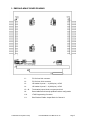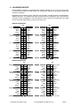
1
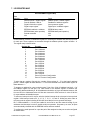
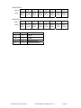
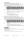
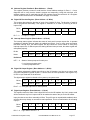
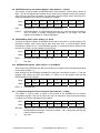
EMERALD-MM-8P
8-Channel Software Programmable Protocol
Serial Port PC/104 Module
User Manual V1.01
© Copyright 2005
DIAMOND SYSTEMS CORPORATION
8430-D Central Ave.
Newark, CA 94560
Tel (510) 456-7800
Fax (510) 456-7878
[email protected]
www.diamondsystems.com
TABLE OF CONTENTS
1.
DESCRIPTION..................................................................................................................................... 3
2.
FEATURES ........................................................................................................................................... 3
3.
EMERALD-MM-8P BOARD DRAWING......................................................................................... 4
4.
I/O HEADER PINOUTS...................................................................................................................... 5
5.
I/O HEADER PIN DEFINITIONS ..................................................................................................... 7
6.
BOARD CONFIGURATION .............................................................................................................. 8
6.1 PORT AND INTERRUPT REGISTER ADDRESS SELECTION ................................................................... 8
6.2 RS-422 / RS-485 CABLE ENDPOINT TERMINATION......................................................................... 9
6.3 INTERRUPT SHARING ....................................................................................................................... 9
7.
I/O REGISTER MAP......................................................................................................................... 10
8.
I/O REGISTER DETAIL................................................................................................................... 12
8.1
8.2
8.3
8.4
8.5
8.6
8.7
8.8
8.9
8.10
8.11
9.
ADDRESS POINTER / ENABLE REGISTER (BASE ADDRESS + 0, READ/WRITE)............................... 12
ADDRESS / IRQ / PROTOCOL DATA REGISTER (BASE ADDRESS + 1, WRITE) ............................... 12
ADDRESS REGISTER READBACK (BASE ADDRESS + 1, READ) ...................................................... 13
DIGITAL I/O DIRECTION REGISTER (BASE ADDRESS + 2, WRITE) ................................................ 13
INTERRUPT STATUS REGISTER (BASE ADDRESS + 2, READ) .......................................................... 13
DIGITAL I/O OUTPUT REGISTER (BASE ADDRESS + 3, WRITE)..................................................... 13
DIGITAL INPUT REGISTER (BASE ADDRESS + 3, READ) ................................................................ 13
EEPROM COMMAND AND ADDRESS REGISTER (BASE ADDRESS + 4, WRITE) ............................ 14
EEPROM BUSY STATUS (BASE ADDRESS + 4, READ) ................................................................. 14
EEPROM DATA REGISTER (BASE ADDRESS + 5, READ/WRITE).................................................. 14
CONFIGURATION REGISTER RELOAD COMMAND (BASE ADDRESS + 6, WRITE) ........................... 14
EEPROM OPERATION.................................................................................................................... 15
9.1 EEPROM MAP AND DESCRIPTION ................................................................................................ 15
9.2 HOW TO USE THE EEPROM .......................................................................................................... 16
10.
INSTALLING EMERALD-MM-8P IN YOUR SYSTEM.......................................................... 17
11.
SPECIFICATIONS ........................................................................................................................ 19
12.
ST16C554 QUAD UART DATASHEET ...................................................................................... 20
© 2005 Diamond Systems Corp.
Emerald-MM-8P User Manual V1.00
Page 2
EMERALD-MM-8P
8-Channel Software Configurable Protocol
Serial Port PC/104 Modules
1. DESCRIPTION
Emerald-MM-8P is a PC/104 I/O module with 8 serial ports with protocols that are software
programmable.
I/O addresses and interrupt levels are programmable for each port, allowing maximum
configuration flexibility. For applications where fixed addresses are desirable, four groups of
preset addresses are provided that can be selected by jumper settings.
Two I/O headers are provided, with four serial ports on each header. The board operates on +5V
only, eliminating the need for a +12V supply that is often required for serial port operation.
Emerald-MM-8P is based on the 16C554 quad serial port IC. This device contains 4 identical
sets of registers, one for each port, and is compatible with the standard PC serial port. Each port
contains a 16-byte FIFO. Complete descriptions of these registers may be found in the Appendix.
Most users will not need this programming information, as it is normally handled by the operating
system’s communications software.
2. FEATURES
♦
♦
♦
♦
♦
♦
♦
♦
♦
♦
♦
8 serial ports with 16-byte FIFOs.
Software Configurable RS-232 / RS-422 / RS-485.
Up to 115.2kbps in standard configuration (460.8kbps available).
Software selectable I/O addresses and interrupt levels.
EEPROM storage of configuration data for instant availability on power-up.
I/O lines are short circuit protected.
8 programamble digital I/O lines (1 per port).
Dual 40-pin I/O headers, 4 ports per header.
+5V only operation.
Extended temperature (-40 to +85oC) operation.
PC/104 form factor.
© 2005 Diamond Systems Corp.
Emerald-MM-8P User Manual V1.00
Page 3
3. EMERALD-MM-8P BOARD DRAWING
J1:
PC/104 bus 8-bit connector
J2:
PC/104 bus 16-bit connector
J3:
I/O header for ports 1 – 4 (2x20 pins) + 4 DIO
J4:
I/O header for ports 5 – 8 (2x20 pins) + 4 DIO
J5 – J8:
Termination jumper blocks, two ports per block
J9:
Board address and interrupt pulldown resistor configuration
J10:
JTAG Programming Connector
J11:
Bias Resistor Enable Jumper Block for Channel 4
© 2005 Diamond Systems Corp.
Emerald-MM-8P User Manual V1.00
Page 4
4. I/O HEADER PINOUTS
Emerald-MM-8P provides two identical 40-pin headers labeled J3 and J4 for the serial ports.
Four ports are contained on each header. Pin numbers are marked on the board to assist with
connector orientation.
Depending on the model you have, each port may be fixed in a single protocol or configurable for
different protocols. The template connector pinouts below are provided to show the pinout for
each port in each configuration. The actual pinout of each connector will depend on the model
you have and the configuration you have set for each port.
RS-232 Configuration:
J3
Port 1
Port 2
Port 3
Port 4
DCD 1
RXD 1
TXD 1
DTR 1
GND
DCD 2
RXD 2
TXD 2
DTR 2
GND
DCD 3
RXD 3
TXD 3
DTR 3
GND
DCD 4
RXD 4
TXD 4
DTR 4
GND
1
3
5
7
9
11
13
15
17
19
21
23
25
27
29
31
33
35
37
39
J4
2
4
6
8
10
12
14
16
18
20
22
24
26
28
30
32
34
36
38
40
DSR 1
RTS 1
CTS 1
RI 1
DIO A
DSR 2
RTS 2
CTS 2
RI 2
DIO B
DSR 3
RTS 3
CTS 3
RI 3
DIO C
DSR 4
RTS 4
CTS 4
RI 4
DIO D
Port 5
Port 6
Port 7
Port 8
DCD 5
RXD 5
TXD 5
DTR 5
GND
DCD 6
RXD 6
TXD 6
DTR 6
GND
DCD 7
RXD 7
TXD 7
DTR 7
GND
DCD 8
RXD 8
TXD 8
DTR 8
GND
1
3
5
7
9
11
13
15
17
19
1
3
5
7
9
11
13
15
17
19
DSR 5
RTS 5
CTS 5
RI 5
DIO E
DSR 6
RTS 6
CTS 6
RI 6
DIO F
DSR 7
RTS 7
CTS 7
RI 7
DIO G
DSR 8
RTS 8
CTS 8
RI 8
DIO H
2
4
6
8
10
12
14
16
18
20
2
4
6
8
10
12
14
16
18
20
RS-422 Configuration:
J3
Port 1
Port 2
Port 3
Port 4
NC
TXD+ 1
GND
RXD+ 1
GND
NC
TXD+ 2
GND
RXD+ 2
GND
NC
TXD+ 3
GND
RXD+ 3
GND
NC
TXD+ 4
GND
RXD+ 4
GND
1
3
5
7
9
11
13
15
17
19
21
23
25
27
29
31
33
35
37
39
2
4
6
8
10
12
14
16
18
20
22
24
26
28
30
32
34
36
38
40
© 2005 Diamond Systems Corp.
J4
NC
TXD- 1
RXD- 1
NC
DIO A
NC
TXD- 2
RXD- 2
NC
DIO B
NC
TXD- 3
RXD- 3
NC
DIO C
NC
TXD- 4
RXD- 4
NC
DIO D
Port 5
Port 6
Port 7
Port 8
NC
TXD+ 5
GND
RXD+ 5
GND
NC
TXD+ 6
GND
RXD+ 6
GND
NC
TXD+ 7
GND
RXD+ 7
GND
NC
TXD+ 8
GND
RXD+ 8
GND
1
3
5
7
9
11
13
15
17
19
1
3
5
7
9
11
13
15
17
19
2
4
6
8
10
12
14
16
18
20
2
4
6
8
10
12
14
16
18
20
NC
TXD- 5
RXD- 5
NC
DIO E
NC
TXD- 6
RXD- 6
NC
DIO F
NC
TXD- 7
RXD- 7
NC
DIO G
NC
TXD- 8
RXD- 8
NC
DIO H
Emerald-MM-8P User Manual V1.00
Page 5
RS-485 Configuration:
J3
Port 1
Port 2
Port 3
Port 4
NC
TXD/RXD+ 1
GND
NC
GND
NC
TXD/RXD+ 2
GND
NC
GND
NC
TXD/RXD+ 3
GND
NC
GND
NC
TXD/RXD+ 4
GND
NC
GND
1
3
5
7
9
11
13
15
17
19
21
23
25
27
29
31
33
35
37
39
© 2005 Diamond Systems Corp.
J4
2
4
6
8
10
12
14
16
18
20
22
24
26
28
30
32
34
36
38
40
NC
TXD/RXD- 1
NC
NC
DIO A
NC
TXD/RXD- 2
NC
NC
DIO B
NC
TXD/RXD- 3
NC
NC
DIO C
NC
TXD/RXD- 4
NC
NC
DIO D
Port 5
Port 6
Port 7
Port 8
NC
TXD/RXD+ 5
GND
NC
GND
NC
TXD/RXD+ 6
GND
NC
GND
NC
TXD/RXD+ 7
GND
NC
GND
NC
TXD/RXD+ 8
GND
NC
GND
Emerald-MM-8P User Manual V1.00
1
3
5
7
9
11
13
15
17
19
1
3
5
7
9
11
13
15
17
19
2
4
6
8
10
12
14
16
18
20
2
4
6
8
10
12
14
16
18
20
NC
TXD/RXD- 5
NC
NC
DIO E
NC
TXD/RXD- 6
NC
NC
DIO F
NC
TXD/RXD- 7
NC
NC
DIO G
NC
TXD/RXD- 8
NC
NC
DIO H
Page 6
5. I/O HEADER PIN DEFINITIONS
Signal Name
RS-232:
DCD
DSR
RXD
RTS
TXD
CTS
DTR
RI
Definition
Direction
Data Carrier Detect
Data Set Ready
Receive Data
Request To Send
Transmit Data
Clear To Send
Data Terminal Ready
Ring Indicator
Input
Input
Input
Output
Output
Input
Output
Input
RS-422:
TXD+, TXDRXD+, RXD-
Differential Transmit Data
Differential Receive Data
Output
Input
RS-485:
TXD/RXD+
TXD/RXD-
Differential Transmit/Receive +
Differential Transmit/Receive -
Bi-directional
Bi-directional
Common to all protocols:
DIO A – H
Digital I/O lines
GND
Ground
NC
Not Connected
© 2005 Diamond Systems Corp.
Programmable
---
Emerald-MM-8P User Manual V1.00
Page 7
6. BOARD CONFIGURATION
Refer to the Drawing of Emerald-MM-8P on page 4 for locations of the configuration items
mentioned here.
6.1 Port and Interrupt Register Address Selection
Each peripheral board in the computer system must have a unique I/O address or block of
addresses. Emerald-MM actually uses nine I/O address blocks: one for each of the eight serial
ports and one for the board’s configuration registers.
Each port’s address block consists of 8 consecutive addresses, while the configuration and
interrupt status register block occupies four addresses. Jumper block J9 in the lower left corner
of the board is used for configuration of the board’s base address. The serial port I/O addresses
are set in software once this address is known.
To help with the translation between jumper settings and addresses, remember that each jumper
installed corresponds to a 0, and each jumper out corresponds to a 1. The 4 jumpers D C B A
correspond to address bits 9 8 7 6, and address bits 5 – 0 are forced to 0 to determine the base
address.
Board Configuration Register Addresses
(Base Address)
Data
Register
DIO Direction
Register,
Interrupt Status
Register
DIO Register
D
C
B
A
Addr. Pointer
Register
In
In
In
In
Invalid setting
In
In
In
Out
Invalid setting
In
In
Out
In
Invalid setting
In
In
Out
Out
Invalid setting
In
Out
In
In
100
101
102
103
In
Out
In
Out
140
141
142
143
In
Out
Out
In
180
181
182
183
In
Out
Out
Out
1C0
1C1
1C2
1C3
Out
In
In
In
200
201
202
203
Out
In
In
Out
240
241
242
243
Out
In
Out
In
280
281
282
283
Out
In
Out
Out
2C0
2C1
2C2
2C3
Out
Out
In
In
300
301
302
303
Out
Out
In
Out
340
341
342
343
Out
Out
Out
In
380
381
382
383
Out
Out
Out
Out
3C0
3C1
3C2
3C3
© 2005 Diamond Systems Corp.
Emerald-MM-8P User Manual V1.00
Page 8
6.2 RS-422 / RS-485 Cable Endpoint Termination
In RS-422 or RS-485 networks, termination resistors are normally installed at the endpoints of
the cables to minimize reflections on the lines. Emerald-MM-8P provides 120Ω resistors for this
purpose. To enable resistor termination for a port, install jumpers in the locations T and R of that
port’s corresponding configuration jumper block (J5 – J8). Termination is only needed, and
should only be used, at the cable endpoints. Enabling these termination resistors at each end of
the cable results in an effective impedance of 60Ω. Installing termination resistors at additional
points in the network may cause overloading and failure of the line drivers due to the lower
impedance caused by multiple resistors in parallel.
6.3 Interrupt Sharing
On the PC/104 bus, interrupt levels may be shared by multiple devices. For this reason, the
interrupt is driven to a logic high level by the device requesting service, and when the device is
serviced it tristates the line rather than driving it low. This technique avoids contention by two
devices trying to drive the line with opposing logic levels.
In order to guarantee valid logic levels on the line when the device is not requesting service, each
active interrupt level requires a 1KΩ pulldown resistor. Only one such resistor should be used on
each active interrupt line. For each interrupt level availabe on Emerald-MM-8P, there is a position
on J9 with that interrupt level no. for enabling the pulldown resistor. Install a jumper in this
position to connect the resistor, and remove the jumper to disconnect the resistor.
6.4 UART Clock Selection
For those applications that require high baud rates a jumper is provided on J9 labeled “CK” to
select 7.3728MHz for the UART clock source when installed, and 1.8432MHz for the UART
clock source when not installed.
Most standard serial drivers assume a 1.8432MHz clock source, so the jumper should remain off
to be compatible with driver baud selection.
6.5 Power Up Port Enable
For those applications that require all ports to be disabled during power-up a jumper is provided
on J9 labeled “PD” to enable all configured ports during power-up when installed or disable all
ports during power up when not installed.
6.6 Port D Bias Jumpers
For those RS423 and RS485 applications where bias resistors are not needed there are jumpers
located at J11 to enable biasing when installed and disable biasing when not installed.
© 2005 Diamond Systems Corp.
Emerald-MM-8P User Manual V1.00
Page 9
7. I/O REGISTER MAP
Emerald-MM-8P Register Map
Base
Address +
0
1
2
3
4
5
6
7
Write
Address pointer / enable register
Data for address / IRQ no.
Digital I/O direction register
Digital output register
EEPROM read/write + address
EEPROM data (write operation)
Reload command
N/A
Read
Address pointer / enable register
Readback of address registers
Interrupt status register
Digital input / readback register
EEPROM busy status
EEPROM data (read operation)
N/A
N/A
Emerald-MM-8P contains 18 additional registers for selecting the address and and interrupt level
for each port. These registers are accessed through the address pointer register at Base + 0.
The register map is shown below:
Register No.
0
1
2
3
4
5
6
7
8
9
10
11
12
13
14
15
16
17
Function
Port 0 Address
Port 1 Address
Port 2 Address
Port 3 Address
Port 4 Address
Port 5 Address
Port 6 Address
Port 7 Address
Port 0 IRQ No.
Port 1 IRQ No.
Port 2 IRQ No.
Port 3 IRQ No.
Port 4 IRQ No.
Port 5 IRQ No.
Port 6 IRQ No.
Port 7 IRQ No.
Ports 0-3 Protocol Configuration
Ports 4-7 Protocol Configuration
To write data to a register, first write the number of that register (0 – 17) to the board’s address
pointer / enable register at Base address + 0. Then write the data to the board’s data register at
Base address + 1.
To program an address for a port, write the upper 7 bits of the 10 bit I/O address into bits 6 – 0 of
the address register for that port. The value written to the address register is therefore the
desired I/O address divided by 8. All I/O addresses should be on 8 byte boundaries between 100
Hex and 3F8 Hex. Addresses below 100 Hex are reserved for CPU functions. A value of 00 Hex
for a port address will disable that port.
To select an interrupt level for a port, write the desired interrupt level to that port’s interrupt level
register. Valid interrupt levels are 2, 3, 4, 5, 6, 7, 10, 11, 12, and 15. Writing any other value to
the interrupt level register including 00 Hex will cause that port not to generate interrupts.
Bit 7 of Base address + 0 is the port enable bit and must be set after manual loading of port
addresses and interrupts in order to enable serial port operation. On power-up or reset, all ports
are automatically reloaded with the EEPROM values and then enabled.
To configure the serial protocol for a port the pair of bits assigned to that port must be configured
as shown below:
© 2005 Diamond Systems Corp.
Emerald-MM-8P User Manual V1.00
Page 10
REGISTER #16
Bit No.
7
6
5
4
3
2
1
0
Name
Port 3
Port 3
Port 2
Port 2
Port 1
Port 1
Port 0
Port 0
CFG1
CFG0
CFG1
CFG0
CFG1
CFG0
CFG1
CFG0
REGISTER #17
Bit No.
7
6
5
4
3
2
1
0
Name
Port 7
Port 7
Port 6
Port 6
Port 5
Port 5
Port 4
Port 4
CFG1
CFG0
CFG1
CFG0
CFG1
CFG0
CFG1
CFG0
CFG1
CFG0
0
0
RS232
0
1
RS422
1
0
RS485 with Echo
1
1
RS485 without Echo
© 2005 Diamond Systems Corp.
PROTOCOL
Emerald-MM-8P User Manual V1.00
Page 11
8. I/O REGISTER DETAIL
8.1 Address Pointer / Enable Register (Base Address + 0, Read/Write)
This register selects the address or IRQ register to be programmed and also enables the serial
ports. The value written to this register can be read back for diagnostic purposes.
After writing the address to this register, the appropriate data is written to the data register at
Base address + 1. See 8.2 below.
Bit No.
7
6
5
4
3
2
1
0
Name
ENABLE
X
X
X
A3
A2
A1
A0
ENABLE
Enables chip selects for the 8 serial ports. 1 = enable, 0 = disable
On power-up or reset, all ports are automatically programmed from the EEPROM
and enabled.
When manually programming the address and IRQ registers, this bit must be set
after programming is complete in order to enable the serial ports.
X
Not used
A3 – 0
Address of internal configuration register:
0 – 7 Address registers for ports 0 – 7 respectively
8 – 15 Interrupt level register for ports 0 – 7 respectively
8.2 Address / IRQ / Protocol Data Register (Base Address + 1, Write)
This register is used to write data to the register selected with the address / enable register
described above. The data must be written to this register after the address is selected.
Note that writing to the board’s serial port address and IRQ registers does not cause a writethrough to the corresponding EEPROM registers. The user must explicitly write the data to the
EEPROM to store these settings for future use when the board is reset or the power is cycled.
Bit No.
7
6
5
4
3
2
1
0
Name
X
D6
D5
D4
D3
D2
D1
D0
X
Not used
D6 – 0
Register data;
For address registers, D6 – 0 contains the upper 7 bits of the 10-bit base address of
the serial port. Valid port base addresses are 100 Hex to 3F8 Hex.
For interrupt level registers, Only D3 – 0 are used. Valid values are 2, 3, 4, 5, 6, 7,
10, 11, 12, and 15. Any other value will prevent interrupts from operating on the
selected port.
I/O Address example
Desired I/O address = 140 Hex = 0 1 0 1 0 0 0 0 0 0
Only the upper 7 bits are needed. The three lowest bits are always 0, resulting in all addresses
being on 8-byte boundaries.
Necessary bits = 0 1 0 1 0 0 0 = 28 Hex
An easy way to generate these bits is to divide the I/O address by 8 or shift right 3 places.
© 2005 Diamond Systems Corp.
Emerald-MM-8P User Manual V1.00
Page 12
8.3 Address Register Readback (Base Address + 1, Read)
This register provides a means to read back the current address settings for Ports 1 – 8 as a
diagnostic tool to verify that the board is present and responding. Using this technique, all 8
address registers can be read back, but the IRQ registers cannot be read back. All 18 register
values can be read back from the EEPROM; see page 14 for details.
8.4 Digital I/O Direction Register (Base Address + 2, Write)
This register determines the direction of each of the 8 digital I/O lines. The direction of each bit
can be programmed individually. This register is cleared to 0 on reset or power-up (all bits in
input mode).
Bit No.
7
6
5
4
3
2
1
0
Name
DIR 7
DIR 6
DIR 5
DIR 4
DIR 3
DIR 2
DIR 1
DIR 0
Dir 7 – 0
0 = input, 1 = output
8.5 Interrupt Status Register (Base Address + 2, Read)
The interrupt status register indicates the status of each port’s interrupt request line. It operates
regardless of whether interrupt sharing is enabled (see below). If two or more ports are sharing
the same interrupt level, the status register will still indicate the correct status of each port’s
interrupt request line. If different ports are sharing different interrupt levels, the status register will
still operate properly.
Bit No.
7
6
5
4
3
2
1
0
Name
INT 7
INT 6
INT 5
INT 4
INT 3
INT 2
INT 1
INT 0
Definitions:
INT 7 – 0
Status of interrupt request for each port:
0 = no interrupt request active
1 = interrupt request active
8.6 Digital I/O Output Register (Base Address + 3, Write)
This register programs the digital output lines on the I/O headers. Any line set to output mode
using the configuration register at base + 2 will be set to the value specified in this register. Any
I/O line in input mode will not be affected.
The digital output register is cleared to 0 on power up or system reset.
Bit No.
7
6
5
4
3
2
1
0
Name
Dout 7
Dout 6
Dout 5
Dout 4
Dout 3
Dout 2
Dout 1
Dout 0
Dout 7 – 0 Set digital output line to value specified
8.7 Digital Input Register (Base Address + 3, Read)
This register returns the state of the 8 digital I/O lines on the I/O headers. Any line in output mode
will be read back. Any line in input mode will be read as the state of the pin on the I/O header.
Input pins that are not driven externally will float. They will have an unpredictable readback value,
and the value may change on successive read operations. This is normal behavior for a floating
input pin.
Bit No.
7
6
5
4
3
2
1
0
Name
DIO 7
DIO 6
DIO 5
DIO 4
DIO 3
DIO 2
DIO 1
DIO 0
DIO 7 – 0
Logic state of I/O line 7 - 0
© 2005 Diamond Systems Corp.
Emerald-MM-8P User Manual V1.00
Page 13
8.8 EEPROM Command and Address Register (Base Address + 4, Write)
This register is used to initiate an EEPROM read or write operation. First the data is written to
Base + 5, then the address and read/write bit are written to this register to initiate the operation.
After writing the operation has started, the application program should monitor the Busy bit by
reading this address to know when the operation is complete.
Bit No.
7
6
5
4
3
2
1
0
Name
R/W
EEA6
EEA5
EEA4
EEA3
EEA2
EEA1
EEA0
R/W
Read/Write bit: 1 = write operation, 0 = read operation
EEA6-0
EEPROM address; The EEPROM has 256 bytes; only the lowest 64 are accessible.
Only the lowest 16 contain configuration information for the board. The other
registers are available for customer application.
8.9 EEPROM Busy Status (Base Address + 4, Read)
The Busy bit indicates whether the EEPROM is busy with a read, write, or reload operation. The
application program must monitor this bit after each read, write, or reload operation before
proceeding to another one. If a new EEPROM operation is commenced without waiting for the
previous one to finish, the new operation will be ignored.
Bit No.
7
6
5
4
3
2
1
0
Name
BUSY
X
X
X
X
X
X
X
BUSY
EEPROM Busy status: 1 = busy, 0 = idle
X
Not used
8.10 EEPROM Data Register (Base Address + 5, Read/Write)
When writing to the EEPROM, the data is first written to this register before the address and write
bit are written to Base + 4.
When reading from the EEPROM, the address to read from is first written to Base + 4. Then the
program must monitor the BUSY bit in Base + 4. When it is 0, the program may read the
EEPROM data from this register.
Bit No.
7
6
5
4
3
2
1
0
Name
EED7
EED6
EED5
EED4
EED3
EED2
EED1
EED0
EED7 – 0
EEPROM data
8.11 Configuration Register Reload Command (Base Address + 6, Write)
This register is used to cause a reload of the contents of the EEPROM into the board’s
configuration registers. This can be done at any time, for example to recall known good settings
in case the user loads invalid data into the registers.
Bit No.
7
6
5
4
3
2
1
0
Name
RELOAD
X
X
X
X
X
X
X
RELOAD
Set to 1 to force a reload of the 8 address settings and 8 interrupt level settings from
the EEPROM into the board. The BUSY bit (Base + 4 bit 7) will go high and stay high
until the reload is complete.
X
Not used
© 2005 Diamond Systems Corp.
Emerald-MM-8P User Manual V1.00
Page 14
9. EEPROM OPERATION
9.1 EEPROM Map and Description
Emerald-MM-8P V1 has an EEPROM for storage of the address and interrupt level settings for
each serial port. The EEPROM has 256 bytes total, of which the lowest 64 are addressible. Only
the lowest 18 registers in the EEPROM are used. The first 8 locations (0-7) are used to store the
base address values for the 8 serial ports. The second 8 locations (8-15) are for the 8 interrupt
levels (IRQ numbers). The last two locations (16 and 17) are used to store the port protocol for
each port. The memory map of the EEPROM is identical to the register map for the addresses
and interrupts on Emerald-MM-8P:
EEPROM Address
0
1
2
3
4
5
6
7
8
9
10
11
12
13
14
15
16
17
Function
Port 0 Address
Port 1 Address
Port 2 Address
Port 3 Address
Port 4 Address
Port 5 Address
Port 6 Address
Port 7 Address
Port 0 IRQ No.
Port 1 IRQ No.
Port 2 IRQ No.
Port 3 IRQ No.
Port 4 IRQ No.
Port 5 IRQ No.
Port 6 IRQ No.
Port 7 IRQ No.
Ports 0-3 Protocol Configuration
Ports 4-7 Protocol Configuration
The address values stored in EEPROM are the upper 7 bits of the 10-bit serial port address.
Each serial port uses 8 registers, so the binary base address of each serial port always ends in
000. To determine the value to store in the EEPROM, divide the desired base address by 8:
Desired base address = 120 Hex = 0 1 0 0 1 0 0 0 0 0 = 288 Decimal
EEPROM value = 288 / 8 = 36 Decimal = 24 Hex = 0 1 0 0 1 0 0
These are the 7 uppermost bits of the original base address. This value would be written
to the selected port’s address location in the EEPROM to program that port for
The IRQ numbers stored in EEPROM are the actual IRQ numbers without any changes. Each
port may be programmed for its own IRQ number, or any number of ports may share an IRQ. Not
all IRQs are available in all computers. You will need to test for availability and operability of the
selected IRQ.
NOTE: The serial port base addresses must be distinct from each other and must also be distinct
from the board’s base address. If any serial port’s address is programmed to overlap with the
board’s base address, that port will not be accessible, and the address will have to be
reconfigured.
© 2005 Diamond Systems Corp.
Emerald-MM-8P User Manual V1.00
Page 15
9.2 How to Use the EEPROM
There are three available EEPROM operations: write data, read data, and reload data.
The write and read operations store data in the EEPROM but have no effect on the board’s
configuration settings. The reload operation updates the board’s configuration settings to match
the values stored in the EEPROM.
Note that writing to the board’s serial port address and IRQ registers does not cause a writethrough to the corresponding EEPROM registers. The user must explicitly write the data to the
EEPROM to store these settings for future use when the board is reset or the power is cycled.
The EEPROM contains 256 bytes. However only locations 0 – 63 may be accessed.
Only EEPROM addresses 0 – 17 are used to store data for the configuration of Emerald-MM-8P.
The remaining locations are available for customer application use.
EPROM Write Operation:
1. Write data to Base + 5
2. Write 6-bit address including Write bit (bit 7 = 1) to Base + 4
3. Monitor Busy bit (bit 7) in base + 4 until it is 0
EEPROM Read Operation:
1. Write 6-bit address to Base + 4 (Bit 7 = 0 for read)
2. Monitor Busy bit (bit 7) in base + 4 until it is 0
3. Read data from Base + 5
EEPROM Reload Operation:
1. Write 0x80 (128) to Base + 6 to initiate Reload operation
2. Monitor Busy bit (bit 7) in base + 4 until it is 0
© 2005 Diamond Systems Corp.
Emerald-MM-8P User Manual V1.00
Page 16
10. INSTALLING EMERALD-MM-8P IN YOUR SYSTEM
Diamond Systems provides utility programs to configure the Emerald-MM-8P board for use in
your computer system. For DOS and Windows 9x applications, the program will configure the
address and interrupt settings, store them in the EEPROM on the board, and allow you to store
them in a file which can be used later to program additional boards with the same configuration.
For Windows NT applications, the program will additionally configure the NT registry with the
proper settings according to the configuration you select.
The configuration programs and instructions are in the zip file EMM8.zip that is included in the
board’s software diskette. For DOS and Windows 9x applications, complete instructions are in
the file readme.txt in the DOS-9x folder, and the application program is called eepconf.exe. For
Windows NT applications, complete instructions are in the file EMM8-NT.txt in the NT folder, and
the application is called Emm8Conf.exe.
The instructions below may be used to manually set up Windows NT to run with the board.
However these instructions are not needed if Emm8Conf.exe is used.
1. Run REGEDT32.EXE and go to the following dialog box:
Key_Local_Machine \ System \ CurrentControlSet \ Service \ Serial \ Parameters
2. Add a new key for each serial port by selecting Edit \ Add Key. The following parameters
need to be specified for each serial port:
SerialN (N = serial port number, 1, 2, 3, 4, etc.):
Parameter
DosDevices
ForceFifoEnable
Interrupt
InterruptStatus
Type
REG_SZ
REG_DWORD
REG_DWORD
REG_DWORD
PortAddress
PortIndex
REG_DWORD
REG_DWORD
SharedInterrupts
REG_DWORD
Value, Comments
Name of port, e.g. COM5, COM6
0x1 for yes
IRQ level in Hex format, e.g. 0x5 for 5 or 0xA for 10
Address of interrupt status register in Hex, e.g.
0x102; See page 8 for status register addresses
Address or port in Hex, e.g. 0x120 for Hex 120
Bit position in status register: 0x1 for LSB through
0x8 for MSB (Note this is NOT the weighted bit
value); See page 13 for details
0x1 for yes, 0x0 for no
3. Exit REGEDT32.EXE and restart NT.
See the example parameter values on the following page.
© 2005 Diamond Systems Corp.
Emerald-MM-8P User Manual V1.00
Page 17
Windows NT Registry Setup Example
The following example is for 8 ports on an EMM-8P-XT board installed on a CPU that already
contains 2 serial ports called COM1 and COM2. Note that all 8 ports on the Emerald-MM-8P
board share the same interrupt status register, but the bit position changes for each port. The
settings shown are the factory settings for the board. All ports are set to share the same interrupt
number.
Configuration selections:
Port 1
0x100
7
Port 2
0x108
7
Board base address:
Interrupt status register:
0x200
0x202
Address
IRQ No.
Serial3:
DosDevices
ForceFifoEnable
Interrupt
InterruptStatus
PortAddress
PortIndex
SharedInterrupts
Serial4:
DosDevices
ForceFifoEnable
Interrupt
InterruptStatus
PortAddress
PortIndex
SharedInterrupts
Serial5:
DosDevices
ForceFifoEnable
Interrupt
InterruptStatus
PortAddress
PortIndex
SharedInterrupts
Serial6:
DosDevices
ForceFifoEnable
Interrupt
InterruptStatus
PortAddress
PortIndex
SharedInterrupts
Port 3
0x110
7
0x1
0x7
0x202
0x100
0x1
0x1
REG_SZ
COM4
REG_DWORD
REG_DWORD
REG_DWORD
REG_DWORD
REG_DWORD
REG_DWORD
REG_SZ
COM6
REG_DWORD
REG_DWORD
REG_DWORD
REG_DWORD
REG_DWORD
REG_DWORD
© 2005 Diamond Systems Corp.
Port 5
0x120
7
Port 6
0x128
7
Serial7:
DosDevices
REG_SZ
COM3
REG_DWORD
REG_DWORD
REG_DWORD
REG_DWORD
REG_DWORD
REG_DWORD
REG_SZ
COM5
REG_DWORD
REG_DWORD
REG_DWORD
REG_DWORD
REG_DWORD
REG_DWORD
Port 4
0x118
7
0x1
0x7
0x202
0x120
0x5
0x1
REG_SZ
COM8
REG_DWORD
REG_DWORD
REG_DWORD
REG_DWORD
REG_DWORD
REG_DWORD
0x1
0x7
0x202
0x128
0x6
0x1
ForceFifoEnable
Interrupt
InterruptStatus
PortAddress
PortIndex
SharedInterrupts
REG_SZ
COM9
REG_DWORD
REG_DWORD
REG_DWORD
REG_DWORD
REG_DWORD
REG_DWORD
0x1
0x7
0x202
0x130
0x7
0x1
Serial10:
DosDevices
ForceFifoEnable
Interrupt
InterruptStatus
PortAddress
PortIndex
SharedInterrupts
REG_SZ
COM10
REG_DWORD 0x1
REG_DWORD 0x7
REG_DWORD 0x202
REG_DWORD 0x138
REG_DWORD 0x8
REG_DWORD 0x1
ForceFifoEnable
Interrupt
InterruptStatus
PortAddress
PortIndex
SharedInterrupts
ForceFifoEnable
Interrupt
InterruptStatus
PortAddress
PortIndex
SharedInterrupts
Serial9:
DosDevices
0x1
0x7
0x202
0x110
0x3
0x1
0x1
0x7
0x202
0x118
0x4
0x1
Port 8
0x138
7
REG_SZ
COM7
REG_DWORD
REG_DWORD
REG_DWORD
REG_DWORD
REG_DWORD
REG_DWORD
Serial8:
DosDevices
0x1
0x7
0x202
0x108
0x2
0x1
Port 7
0x130
7
Emerald-MM-8P User Manual V1.00
Page 18
11. SPECIFICATIONS
Serial Ports
No. of serial ports:
8
Protocols:
Maximum baud rate:
EMM-8P-XT:
RS-232, RS-422, RS-485
115kbps standard version
460.8kbps available by special order – contact factory
5, 6, 7, or 8 data bits; Even, odd, or no parity
All outputs protected against continuous short circuit
Communications parameters:
Short circuit protection:
RS-232 mode:
Input impedance:
3KΩ min
Input voltage swing:
±30V max
Output voltage swing:
±5V min, ±7V typical
RS-422, RS-485 modes:
Differential input threshold:
-0.2V min, +0.2V max
Input impedance:
Input current:
12KΩ min
+1.0mA max (VIN = 12V)
-0.8mA max (VIN = -7V)
Differential output voltage:
High/low states differential
output voltage symmetry:
2.0V min (RL = 50Ω)
Digital I/O
0.2V max
(At VCC = 5.0VDC)
No. of I/O lines:
Input voltage:
8 in, 8 out
Low: -0.3V min, 0.8V max
High: 2.0V min, 5.3V max
Output voltage:
Low: 0.0V min, 0.4V max (IOL = 6mA max)
High: 3.7V min, 5.0V max (IOH = -4mA max)
General
I/O header:
Dimensions:
Power supply:
Current consumption:
Operating temperature:
Operating humidity:
PC/104 bus:
© 2001 Diamond Systems Corp.
2 40-position (2x20) .025” square pin header on .1” centers;
Headers mate with standard ribbon cable (IDC) connectors
3.55” x 3.775” LxW (PC/104 standard)
+5VDC ±10%
160mA typical, all outputs unloaded
-40 to +85oC (Industrial range)
5% to 95% noncondensing
8 bit and 16-bit bus headers are installed and used (16-bit
header is used for interrupt levels only)
Emerald-MM-8 User Manual V2.33
Page 19
12. ST16C554 QUAD UART DATASHEET
© 2001 Diamond Systems Corp.
Emerald-MM-8 User Manual V2.33
Page 20