1
HAL MSIU Software User Manual
HIDEN ANALYTICAL LTD
420 Europa Boulevard
Gemini Business Park
Warrington
WA5 5UN
England
Tel
Fax
01925
01925
445225
416518
TITLE
HAL MSIU Software User Manual
AUTHOR
Steve Doughton
DATE
24 January, 2003
SUMMARY
This document describes the remote mass spec. controller commands.
NOTE: this document is intended for INTERNAL USE.
NOTE
This document is intended for internal use, if distributed to customers
this document is provided "as is"; the information herein is not
guaranteed accurate or complete and is subject to change by Hiden
without notice.
SOFTWARE REVISION
This document is
702m ).
applicable to release 3.2
of the firmware ( HA-061-
DOCUMENT REVISION HISTORY
Revision 0 :
Preliminary draft . 30 Mar 1993
Revision 1 :
Current state of interface on 18 June 1993.
Unimplemented command shown with grey background.
Revision 2 :
More info on returned value formats and errors added.
Scan results parameter documented. 22 July 1993.
Revision 3 :
8th Sept 1993 : SJOB STAT SVAL SOUT SERR RBUF & RERR
commands implemented. terminator parameter implemented. Error summary
updated.
Revision 4 :
25 Oct 1993 : DATA command implemented. report field
implemented. cycles and points parameters implemented.
Revision 5 :
2 Nov 1993 : Section 1 culled from specification
document & re-written. current and mode fields documented. SDEL all
HA-085-006a 24.01.03
Page 1 of 93
System Description
Key Concepts
command documented.
Revision 6:
19 Aug 1994:
Scan option & return fields documented.
Mass alignment procedure added. Trip priority field documented. Standby
mode renamed Shutdown. DATA on and DATA off documented.
Revision 7:
28 March 1996: QUIT TEST & HELP commands documented.
Scan cycles, interval & state fields documented. Group documentation
updated. Logical device descriptions updated. Error summary updated.
Operation sequence added
Revision 8:
devices.
23rd May 1996: Added documentation for test EPROM
Revision 9:
8th July 1996: Added documentation of ESP EPROM
devices. Documented range device operation. Data Event enhancements (
SM51 ) documented. Documented BOOT command.
Revision 10:
3rd January 1997: Changed name from HAL 68K Software
User Manual to HAL MSIU Software User Manual. Issued as HA-085-006
Revision a.
HA-085-006a 24.01.03
HAL MSIU Software User Manual
Page 2 of 93
System Description
Key Concepts
1. System Description
1.1. Key Concepts
This software is built on two key concepts, the logical device and the
scan. These two are inter-related in that a table of scans is
represented by a scan logical device.....
1.1.1.
The Logical Device
A logical device is a way of associating a name with a hardware
or software function. By asking the controller what logical devices are
available a remote computer may find out the capabilities of the
system. Once the names of the available logical devices are known the
remote computer may enquire the capabilities of each device by use of
the commands LMIN, LMAX, LRES, LUNT, LUSE, LTYP and LVAL. These
commands return values that have been configured into the logical
device table in the EEPROMs. Their use is documented in section 2.
Each logical device has a corresponding logical device number .
The command LID# may be used to obtain this, given the devices name.
Logical device numbers may vary from system to system so should always
be obtained by use of the LID# command. Once known their use is quicker
than using the logical device name, but logical device names and
numbers may be used interchangeably in most commands ( For future
reference : this also applies to Parameter names and numbers and Field
names and numbers ).
The command LSET may be used to set a logical device to a value
and LGET to read a value. Thus LSET mass 28 sets the mass DAC to 28 and
LGET SEM will read the SEM and display the result.
The command LINI is used to initialise a device.
Logical devices may be grouped together in a group logical
device. Thus all devices that need initialising are in the "all"
group. The names of these devices may be obtained by the command LID$
all which will display their names as a comma separated string. . To
initialise all devices use LINI all. The LINI command is executed on
each device in the all group in turn.
All the group logical devices are themselves in the "groups"
group. This device should always be present in the configuration. By
using LID$ groups the remote computer may enquire what groups the
system supports. By then doing LID$, using each of the group names
returned , the devices in each group may be obtained.
Groups may be used to suggest to the remote computer which
devices to use for a particular purpose, e.g. devices in the "source"
group for source tuning. For these groups using the LSET command will
generate an error, though LINI source might be useful to reset the
source DACs to their default values.
Groups may also be used to change the value of a number of DACs
simultaneously. An example of this is the "mode" group. SIMS systems
may operate in 3 modes :- RGA, SIMS +ve ion and SIMS -ve ion. Initial
values for each mode are configured into the logical device table entry
of every device in the mode group. Each mode represents a "state" of
the logical devices comprising the group. The logical device table has
HA-085-006a 24.01.03
HAL MSIU Software User Manual
Page 3 of 93
System Description
Key Concepts
room for 7 states for each device.
The state of a group may be changed using the LSET command. LSET
mode 2 will change all devices in the mode group to the value
appropriate for SIMS +ve ion operation. Once a state has been selected
you may use LSET to tune an individual device in the group. The value
set will be stored in the state of the device according to the mode.
LGET mode will return the last value of mode set.
When a remote computer initially interrogates the controller it
will need to know the settings of all states of a device. The command
LVAL returns the device state followed by 7 values, one for each
state. and by the calibration intercept and slope.
The reverse of this command is LPUT, which allows the 7 values
corresponding to each state to be downloaded. LPUT does not change the
state, but does set the device to the new value for its current state.
Devices may be calibrated using the LINT & LSLO commands to set
the intercept and slope. The intercept is expressed in the units of the
device to 6 decimal places using the default slope. Rounding errors may
occur in its calculation so take care if you are reading it and setting
it back again that the value does not creep up or down. The slope is
expressed as a ratio to the default.
1.1.2.
The Scan
As noted above the command LSET may be used to set a logical
device to a value and LGET to read a value. Thus LSET mass 28 sets the
mass DAC to 28 and LGET SEM will read the SEM and display the result. A
scan can be programmed to do this automatically:
SSET
SSET
SSET
SSET
SINI
SSET
scan Ascans
row 1
input mass
start 28
step
input SEM
These commands set up a scan table for the scan logical device
Ascans.:
SCAN
Ascans
ROW
1
START
28
STOP
28
STEP
0.02
INPUT
SEM
OUTPUT
mass
The above example just measures mass 28, to scan over a range of
masses use:
SSET start 28
SSET stop 40
SSET step 1
Which sets up the table:
SCAN
Ascans
ROW
1
START
28
STOP
40
STEP
1
INPUT
SEM
OUTPUT
mass
scan, row, start, stop, step, input, output, are field names.
HA-085-006a 24.01.03
HAL MSIU Software User Manual
Page 4 of 93
System Description
Key Concepts
Fields correspond to the columns in the scan logical device's table.
The syntax of the commands the operate on fields is similar to those
that operate on logical devices. Many logical device commands have
their equivalent field command, but beginning with S instead of L: SGET
SSET SMIN SMAX SID$ SID# and SINI. Like logical devices fields may be
referred to by their name or field number, as returned by SID#. See
section 2 for details of field commands and field names.
A sequence of scan steps may be set up by entering values for
other rows:
SCAN
Ascans
Ascans
Ascans
Ascans
ROW
1
2
3
4
START
18
28
32
40
STOP
18
28
32
40
STEP
1
1
1
1
INPUT
SEM
SEM
SEM
SEM
OUTPUT
mass
mass
mass
mass
Ascans may be acquired by the following command sequence:
LINI Ascans
LGET Ascans
Note that you initialise and get the logical device. LGET Ascans
scans each row of Ascans for all indices from its start value to its
stop value. LSET may be used to execute a scan logical device 1 step
at a time, the value set specifying the index of the step. Thus with
START 10 , STOP 20 and STEP 1 LSET Ascans 1 would measures at mass 10,
LSET Ascans 2 would measure at mass 11 and so on. Where START = STOP
the index value does not matter.
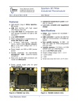
Thus scan may be envisaged as having 1 input device and 1 output
device, in addition it has an index input and a data output to Report.
The scan has 2 main parameters, the start value and the stop value:
index
Start
Stop
Output
Figure
Report
Input
1
The output device will normally
device the main input ( e.g. the SEM
between Start and Stop are output to
the input device is called to return
be the mass DAC and the input
ADC or pulse counter ). The values
the Output device and each time
a value.
The input and output devices may be any logical device ( though
using some make more sense than others ) including a scan logical
device.
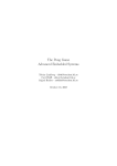
Now let us replace the SEM input with a scan logical device,
Bscans. Bscans outputs to the energy DAC:
HA-085-006a 24.01.03
HAL MSIU Software User Manual
Page 5 of 93
System Description
Key Concepts
index
Start
Stop
Ascans
Output
Report
OFF
Input
MASS
index
Bscans
Start
Stop
Output
Input
SEM (pulse counter)
ENERGY
Figure
Report
ON
2
In this case Ascans will scan mass between Start and Stop, at
each step it will output the mass then call Bscans to input a value;
Bscans will then scan the energy between its start and stop, inputting
readings from SEM.
The structure in figure 2 represents a 2 dimensional scan. By
chaining scans to the input as many dimensions as desired may be built
up.
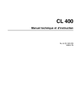
Now let us place Bscans as an output to Ascans:
index
Ascans
Start
Stop
Output
Start
Stop
Output
ON
Input
SEM (pulse counter)
index
Bscans
Report
Report
OFF
Input
mass
Figure
3
In figure 3 Ascans calls Bscans for each step between its Start
and Stop. Each time Bscans is called it is clocked once and advances 1
step between its Start and Stop, outputting to mass each time it does
so. There is no input to Bscans. Having called Bscans to set the mass
Ascans reads SEM.
This is functionally equivalent to figure 1. This structure only
HA-085-006a 24.01.03
HAL MSIU Software User Manual
Page 6 of 93
System Description
Key Concepts
becomes useful if you have lists of scans:
index
Ascans[1]
Output
Start
Stop
Report
ON
Input
SEM (pulse counter)
index
Bscans[1]
Start
Stop
Report
OFF
Output
mass
Input
index
Bscans[2]
Start
Stop
Report
OFF
Output
energy
Input
index
Bscans[3]
Start
Stop
Output
plates
Figure
Report
OFF
Input
4
Now each time Ascans clocks Bscans the mass , energy and plates
all increment by 1 step, then Ascans reads SEM. When Bscans is used as
an output to Ascans the behaviour of Bscans does depend on Ascans's
Stop and Start. Ascans' Stop and Start may be regarded as indices to
Bscans' Stop and Start. Thus if Ascans scans from w to x and Bscans
from y to z then when Ascans clocks Bscans it can scan from y+w-1 to
min(y+x-1,z) - assuming unit step sizes. To ensure that all Bscans
steps can be run a stop value of ∞ must be provided in Ascans' stop.
In figure 4 none of Bscans' scans have inputs. Although I see no
reason to prohibit output scans having inputs, great care would have to
be taken in their use because Bscans[1]'s input would be read before
Bscans[2]'s output had been set. If two inputs are required Bscans[3]'s
input and Ascans' input may be used, if more inputs are required then
dummy output devices are needed at the end of the Bscans list.
HA-085-006a 24.01.03
HAL MSIU Software User Manual
Page 7 of 93
System Description
Key Concepts
If a list of scans, Bscans[1] to [3] as above, was used as an
input device then Bscans[1] would scan from its Start to Stop then
Bscans[2] would scan from its Start to Stop and finally Bscans[3] would
scan from its Start to Stop. The value returned would be the value
returned by Bscans[3].
Putting Xscans into a logical device in a scan will call that
scan as a logical device; however calling it from within a scan will is
exactly the same as the commands LGET Xscans or LSET Xscans because the
commands must perform initialisation which it is undesirable to repeat
from within a scan.
To prevent circular definitions the scans are hierarchical, only
being able to call a lower level scan : so Ascans may call Bscans to
Zscans, but Bscans may not call Ascans.
In tabular form the scans may be represented as follows:
An ordinary MID type table:
SCAN
Ascans
Ascans
Ascans
Ascans
ROW
1
2
3
4
START
18
28
32
40
STOP
18
28
32
40
STEP
1
1
1
1
INPUT
SEM
SEM
SEM
SEM
OUTPUT
mass
mass
mass
mass
A 2 dimensional scan, scanning Energy from -5 to 10 and mass from
1 to 55 avoiding mass 28.
SCAN
Ascans
Bscans
Bscans
START
-5
1
29
STOP
10
27
55
STEP
1
1
1
INPUT
Bscans
SEM
SEM
REPORT
no
yes
yes
OUTPUT
energy
mass
mass
REPORT
no
no
no
To scan the plate voltage with the mass the following may be
used:
SCAN
Ascans
Bscans
Bscans
START
1
1
7.2
STOP
150
150
7.6
STEP
1
1
0.0026
8
INPUT
SEM
NONE
NONE
REPORT
yes
no
no
OUTPUT
Bscans
mass
plate
REPORT
no
no
no
To use the above format easily will require the implementation of
the STEP field in the form where the step value indicates the total
number of steps, not the increment as 0.00268 is less than the
resolution of the plate DAC.
All three of the above may be combined: A 2 dimensional scan of
energy and mass of selected masses, with the plate voltage tracking
the mass:
SCAN
Ascans
Bscans
Bscans
Bscans
Bscans
START
-5
18
28
32
40
HA-085-006a 24.01.03
STOP
10
18
28
32
40
STEP
1
1
1
1
1
INPUT
Bscans
SEM
SEM
SEM
SEM
REPORT
no
yes
yes
yes
yes
HAL MSIU Software User Manual
OUTPUT
energy
Cscans
Cscans
Cscans
Cscans
REPORT
no
no
no
no
no
Page 8 of 93
System Description
Cscans
Cscans
1
7.2
300
8.0
Glossary
1
0.0026
8
NONE
NONE
no
no
mass
plate
no
no
1.2. Glossary
Apex scan The scan logical device at the top of the scan tree. When
Ascans calls Bscans as an input or output device and Ascans is the scan
acquired by the LGET command then Ascans is the apex scan.
Command
The first 4 non-space characters on each input line are
interpreted as a command. Commands are available to manipulate logical
devices, parameters and the scan tables associated with scan logical
devices.
Environment
There are two environments. The system environment is
the state of all logical devices. Each scan may have a local
environment, a list of logical devices and values that apply only
during that scan.
Event A component of an event sequence. ( Formerly called a trip. The
term trip is now reserved for intensity trips and X axis set points.)
Events may be strung together to form "Event Sequences" that can
execute commands, print messages or values and perform simple
calculations. These Event Sequences may be used as the actions of
normal trips or may be run independantly by means of the TRUN command.
See Trip, below.
Field An entry in a row of a scan logical device table, e.g. start,
stop or step.. It may be regarded as the name of a column in the table.
In this manual field names are underlined.
Group Groups are logical devices that operate more than 1 logical
device. Sometimes a group is used merely to identify related devices,
e.g. source identifies those DACs that control the source.
HAL IV
HAL 4 Working title for the HAL RC 2 and HAL RC 6 project during
development.
Logical Device At its simplest a logical device represents a hardware
device. By means of the Logical Device Table the software "knows" about
the capability of a device and how to operate it. By reference to this
table a device may be set to a given value or the value read from the
device. This idea is extended to "devices" that only exist as software,
not as hardware, e.g. the elapsed time clock. This is taken still
further in that a list of scans is a scan logical device and may be set
or read.
The logical devices available depend on the hardware that the
EEPROMs have been configured for.
Mode SIMS systems may operate in 3 modes :- RGA, SIMS +ve ion and SIMS
-ve ion. In addition a Shutdown mode ( always mode 0 ) is provided;
this is used to put the system into a safe state. The mode of the
system is implemented as a group logical device. This enables the
HA-085-006a 24.01.03
HAL MSIU Software User Manual
Page 9 of 93
System Description
Glossary
settings for a number of logical devices to be changed simultaneously
to the value appropriate for that mode. Because the mode interacts with
the local scan environment a scan field, mode, is assigned for the
mode of the scan.
MSIU Mass Spectrometer Interface Unit. The 2U, 6U or 7U unit
containing the electrode power supplies and microprocessor.
Parameter Parameters represent values used by the software. Unlike
logical devices the parameters available depend only on the release of
the software - they are not configured to match the hardware. Like
logical devices their values may be read, and most may be set. A few
are read-only for information only.
Scan A scan is 1 row of a scan logical device table. It controls the
scanning of an input device from a start value to a stop value. At
each step an input is read.
Scan Logical
Device
An abstract logical device representing a table of scans. 26
scan logical devices are available named Ascans to Zscans. Complex
nested scan structures may be built by allowing a scan to call a scan
logical device as an input or output device.
Standby
aka
Shutdown
Mode 0. Used to put the system into a safe state, ie SEM and
first dynode voltages removed and the beam parked. The protection trips
set the system to Shutdown when a trip occurs. Mode 0 will be present
on all instruments and may be assumed, it is not enumerated by the LUNT
mode command.
Stream
A channel of communications e.g. COM1: ( the RS422 port ),
COM2: ( the RS232 port ) DLC1:, DLC2:, DLC3: ( the network ). These
streams may receive commands and can return results, data, errors or
the output from event sequence messages. A stream may also be purely
internal, e.g. NUL:, BUFFER: and ERROR:. These streams can not receive
commands. The names of all streams may be obtained by using the command
PGET stream.
Task To enable more than 1 command to execute at once 6 background
tasks are available. These may be started explicitly by use of the SJOB
command or automatically, e.g. the DATA command. Thus, by use of the
SJOB command, while a scan logical device is scanning tuning commands
may also be sent. Use of SJOB allows a command to be STOPed before it
completes. Two tasks are started automatically at power-up, one is the
TRIP task and the other runs an event sequence that monitors the
inhibit input.
Trip Trips are structures that may be set to check the data as it is
acquired and perform actions should limits be exceeded. This function
is performed by the TRIP command. In addition trips may be strung
together to form trip "programmes". In this context trips are now
termed events and comprise part of event sequences.
See Event, above.
HA-085-006a 24.01.03
HAL MSIU Software User Manual
Page 10 of 93
Main Software Functions
Glossary
2. Main Software Functions
The general intention of the command interface is to have a small set
of commands acting on a large number of logical devices. Fast response
to commands is aided by having a fixed 4 character command format. The
first 4 non-space characters of the command line are interpreted as a
command.
Commands may be divided into 4 groups:
1
Commands associated with the command interface itself.
2
Logical device commands - commands beginning in L.
3
Parameter commands - commands beginning in P.
4
Scan table commands. - commands beginning in S.
5
Trip & Event commands - commands beginning in T
The commands for type 2, 3 4 & 5 commands are, as far as possible
isomorphic. Thus there are L, P S & T versions of the GET, SET, ID#,
ID$, MIN & MAX commands.
NOTE: Commands are not case dependant but logical device names are.
All commands return a Carriage Return on completion. Errors are
returned via the STDERR device. By default this is the same as STDOUT
so errors will be returned prior to any returned value and the terminal
CR. With the terse parameter set to 0 errors return a verbose error
string e.g.:
lset mass 500 *Command error
9
Logical device value out of range*
The error message consists of 3 parts, the error type, the error number
and the error ID$.
With terse set to 1 this error gives:
lset mass 500 *C09*
Here C indicates a command error and 09 the error number. The * * helps
separate the error from any following result. The EID$ command may be
used to get a verbose version of an error from its error number.
The errors associated with the commands in the following sections are
not exhaustive, they are those produced by the standard & default
device drivers; other logical devices may produce device-specific
errors.
Any command of less than 4 characters, including blank lines, produces
the error:
Command error
3
Command truncated
Unrecognised commands produce:
Command error
1
Unknown command
The following flow chart summarises command processing.
HA-085-006a 24.01.03
HAL MSIU Software User Manual
Page 11 of 93
Main Software Functions
Glossary
Send command
to MSIU
Receive character
and buffer
Is character a
carriage
return?
yes
Parse buffer for
errors
Error ?
no
Error messages begin and end with *
E.g. *C001*
Handle error
yes
no
Result
expected ?
yes
no
Interpret
result
End
2.0.1.
Command Streams
Commands may be sent on any input stream. The following input
streams have been implemented: COM1:, COM2:, DLC1:, DLC2:, DLC3:.
Commands received from any input stream are ALWAYS executed by
task 0. Task 0 executes the command until it completes. No other
command can be processed until task 0 completes; Thus, for instance, if
the command LGET SEM were issued then the command task would be tied to
this operation for the duration of the settle and dwell times for the
HA-085-006a 24.01.03
HAL MSIU Software User Manual
Page 12 of 93
Main Software Functions
Glossary
measurement. During this time no other commands can be executed, not
even STOP. Running an event sequence that loops by using the command
TRUN <event> will lock the command task forever. For this reason time
consuming commands must be run in a background task by using the
command SJOB.
NOTE: This is unlike most operating systems. Usually each input stream
executes in its own task.
Unless redirected by the command COUT the output from a command
is sent back to the stream that issued the command. Output is
redirected by the commands COUT, CERR, SOUT and SERR. COUT redirects
results from commands and CERR redirects error messages. Thus errors
can be buffered by redirecting to BUFFER: then polled with the RERR
command. Likewise SOUT and SERR redirect the output of commands
started as backgound tasks by the SJOB command. Each input stream
maintains its own settings for COUT CERR SOUT and SERR, thus each
stream may redirect its output independant of any other stream.
When a command is received on an input stream the corresponding
output stream is locked. This prevents the output from commands
received on any other stream being redirected to it and prevents
background tasks ( e.g. an event sequence ) sending messages to it. Any
task attempting to write to a locked stream will block until a QUIT
command is received on the locked stream. Its status, as shown by the
STAT <task#> command will show as "blocking".
NOTE: Although the MSIU is only intended to be sent commands by one
stream it is capable of receiving commands on any input stream at any
time. If the user wishes to do this they should be aware of the
possibilty of deadlock due to a command, whose output has been
redirected by COUT, blocking when trying to write to the other input
stream's output. The command task will then be deadlocked, as it can
not complete the current command and can not process a QUIT command
from the other stream. A deadlock state of this nature is not detected
by the 32s scheduler watchdog and will not cause the system to re-boot
( See the BOOT command). Use COUT with caution!
2.0.1.1.
The COM1: Stream
The COM1: stream corresponds to the RS422 input. The RS422 input
operates at 19.2Kbaud, No parity, 8 data bits and 1 stop bit. This is
not alterable by the user.
No protocol is used by the RS422, other than that of command and
response or error.
A checksum is not used.
2.0.1.2.
The COM2: Stream
The COM2: stream corresponds to the RS232 input. The RS232 input
operates at 19.2Kbaud, No parity, 8 data bits and 1 stop bit. This is
not alterable by the user.
No protocol is used by the RS232, other than that of command and
response or error.
A checksum is not used.
2.0.1.3.
The DLC1: Stream
DLC1: is an Ethernet LAN stream. The DLC1: stream corresponds to
HA-085-006a 24.01.03
HAL MSIU Software User Manual
Page 13 of 93
Main Software Functions
Command Interface Commands
SAP C0 at the MSIU's Ethernet address. This may be obtained by issuing
the command PGET net-address. The Ethernet address given to HAL IV
MSIUs is a locally adminstered address. Unless otherwise comfigured it
will be 02484100xxxx where xxxx is the unique 4 digit ID given to each
MSIU. This number is shown beneath the serial number on the rear of the
MSIU, it corresponds to the instruments Works Reference number.
The DLC1: stream is connected to the 10Base2 BNC connector. It
operates at 10Mbits per second using ISO 8802-3.
DLC1: uses the ISO 8802-2 Logical Link Control protocol ( LLC II
), compatible with Microsoft's MSDLC.
The SAP is always open. The SAP supports only 1 link station so
only 1 PC may connect to the SAP at any given time.
The parameter "DLC_p_timer" times the interval during which the
LCC shall expect to receive a PDU with the "F" bit set to 1 in response
to a sending a Type 2 command with the P bit set to 1. The default
value is 15 ( 105ms ).
The parameter "DLC_ack_timer" times the interval during which the
LCC shall expect to receive an acknowledgement to one or more
outstanding I PDUs or expect a response PDU to a sent unnumbered
command PDU.The default value is 30 ( 210ms ).
The parameter "DLC_rej_timer" times the interval during which the
LLC shall expect to receive a reply to a REJ PDU.The default value is
15 ( 105ms ).
The parameter "DLC_busy_timer" times the interval that the LLC
waits for a busy state at the other LLC to clear.The default value is
150 ( 1s ).
The parameter "DLC_retries" defines the number of times that a
PDU is sent following the running out of the acknowledgement timer, the
P-bit timer or the reject timer.The default value is 10
The parameter "DLC_tick_timer" scales all the other timers.The
default value is 7. This gives a tick time of 7ms.
2.0.1.4.
The DLC2: Stream
DLC2: is an Ethernet LAN stream. The DLC2: stream corresponds to
SAP C4 at the MSIU's Ethernet address. In all other respects it is
identical to DLC1:.
The DLC2: stream is intended for returning data.
2.0.1.5.
The DLC3: Stream
DLC3: is an Ethernet LAN stream. The DLC3: stream corresponds to
SAP C8 at the MSIU's Ethernet address. In all other respects it is
identical to DLC1:.
The DLC3: stream is intended for redirecting error messages.
2.1. Command Interface Commands
I am not sure how many of these I will be able to implement.
HA-085-006a 24.01.03
HAL MSIU Software User Manual
Page 14 of 93
Main Software Functions
Command Interface Commands
Unimplemented stuff is shown on a grey background.
EID$
EID$ <n> returns the error message string of error <n>.
ESET ESET <n> generates error number <n> on the current error stream.
CMD$ Saves a command string for parsing by CMD=. This will be a dummy
- it will discard the rest of the command line. Use to specify the
columns to edit the scan table.
CMD$ SSET scan, SSET row, SSET output, SSET start, SSET stop, SSET step, SSET input, SSET
rangedev, SSET low, SSET high, SSET current, SSET dwell, SSET settle, SSET mode,
Field numbers can be substituted for field names. Field numbers
can be obtained using the SID# command.
CMD$ SSET 1, SSET 2, SSET 3, SSET 4, SSET 5, SSET 6, SSET 7, SSET 8, SSET 9, SSET 10,
SSET 11, SSET 12, SSET 13, SSET 14,
CMD= Executes each command in the string saved by CMD$, each command
taking its parameters from the current input. This will be implemented
as a command to parse the command line into the scan table in a fixed
format.
example: CMD= Ascans,1,masss,1,100,1,Faraday,range,-10,-7, -7, 50%,100%,1
Logical device numbers may be substituted for logical device
names in the fields corresponding to scan ( 1 - 26 ), output, input and
rangdev. Logical device numbers may be obtained by use of the LID#
command.
COUT Sets the output device of the command task.
example COUT PRINTER
CERR Sets the error device of the command task
example CERR COM2
SJOB Starts a command in the background without waiting for the
result. Thus to run a scan the command required is:
Example : SJOB
LGET Ascans
Returns : Task <task#>, job <job#>,↵
Errors:
If more than 3 background tasks already running:
"Command error
30
No free task"
STOP Stops a background job. Syntax STOP <task#> [<job#>]. Stops job
<job#> in task <task#>. If <job#> is omitted stops the current task. No
error if task is idle.
Example : STOP 1 1234 or
STOP 1
Returns : ↵
Errors:
HA-085-006a 24.01.03
HAL MSIU Software User Manual
Page 15 of 93
Main Software Functions
Error number
Command Interface Commands
31 "Command error
31
Task number out of range"
if <job#> does not match current job:
Error number
32 "Command error
32
Job not running"
DATA Reads the data buffer. This command starts a background task
called "data" ( note lowercase ). When the background task terminates
the data from it is followed by ! .
The number of data points returned by any given DATA command is
specified by the points parameter. PSET points 0 makes the number of
data points unlimited. After the specified number of points, or if the
last point is still being acquired, DATA suspends. The command DATA
without an argument, see below, resumes recall.
Data is returned in almost the same format as is returned by
using the results parameter. See section 2.1.0.1, "Returned Data", page
17.
The results parameter is now obsolete and no longer supported.
The DATA command may be nested. If data is misread another DATA
<scan-dev> <n> command ( see below ) may be issued to read the missed
data. The data should be read until a ! is received or the current DATA
command stopped by DATA stop.
When a scan is initialised ( LINI <scan> ) or started ( LGET
<scan> or LSET <scan> ) all background data commands are stopped.
This command has the following syntax:
DATA <scan-dev-name>
or
DATA <scan-dev-number>
Reports the results of the last cycle of the scan given by
<scan-dev-name> ( E.g. Ascan ) or <scan-dev-num>.
DATA <scan-dev-name>
<n> or
DATA <scan-dev-number> <n>
Reports the results of cycle <n> of the scan given by <scandev-name> ( E.g. Ascan ) or <scan-dev-num>. Each time a scan is
called, either as an input or output ldev, the scan's cycle number is
incremented. Note that the scans' cycle numbers are independent. If
Ascans calls Bscans 4 times Ascans may be on cycle 1 while Bscans is on
cycle 4..
DATA all
Reports all stored data from the head of the stored data
list onward.
DATA
Reports the next available data points. Will automatically
re-start the background task if it has terminated ( ! received ). If
DATA commands have been nested DATA alone after ! un-nests the
previous DATA <scan> command and resumes it.
HA-085-006a 24.01.03
HAL MSIU Software User Manual
Page 16 of 93
Main Software Functions
2.1.0.1.
Command Interface Commands
Returned Data
Scan logical devices can be made to return the readings as they
are taken by using the results parameter. Stored data can be recalled
by the DATA command, the format of the recalled data is determined,
scan by scan, by the report field. The results parameter and the report
field can take a value between 0 & 31. Each of the 5 bits of this value
control part of the output format: The terse parameter determines if
the short form of the reading is returned, with terse = 1 the units are
omitted.
The basic output string of a reading with all fields present (
results or report = 31 ) from a single row, MID type ( start = stop ) ,
scan:
Row
1
Output
mass
Start
1
Stop
1
Step
0.04
Input
SEM
is:
1234/"mass"
1.00 amu:"SEM"0 c/s,
<time><time_units>/"<o/p_dev>"<o/p_value><o/p_units><separator>"<
i/p_dev>"<i/p_reading><i/p_units><comma>
Field
<time>
<time_units>
/
"<o/p dev>"
<o/p_value>
<o/p_units>
<separator>
bit set in
results or
report
4
4 and terse
= 0
4
3
2
2 and
terse=0
2 or 3
"<i/p dev>"
1
<i/p_reading
>
<i/p_units>
0
<comma>
0 and
terse=0
0, 1, 2 or 3
The elapsed time in milliseconds
The units of the elapsed time (
"mSecs" ).
Time separator.
The output logical device name in
quotes
The value set to the output
The units of the output device
The separator is a colon, it is
present if the output device
value is reported in the results
or report.
The input logical device name in
quotes
The value read by the input
logical device
The units of the input device.
Always present if results or
report is > 0
Hence if results or report =31 and terse = 1 ; 1234/"mass"
1.00:"SEM"0,
The device names may be omitted if results or report = 21 ;
1234/1.00:0,
The elapsed time may be omitted if results or report = 5 ;
1.00:0,
To just return the reading use results or report = 1 ; 0,
HA-085-006a 24.01.03
HAL MSIU Software User Manual
Page 17 of 93
Main Software Functions
Command Interface Commands
To aid interpretation of data from complex scan trees data may be
parenthesised by characters in the brackets string parameter. This
contains [](){} by default.
[]
Parenthesise the start and end of a scan cycle. A single cycle,
as started by LGET, will start with [ and end with ].
()
Parenthesise the output of a scan logical device when called as
an input or output device from within a scan.
{}
Parenthesise an individual scan. They are omitted if start =
stop.
Thus, with results or report = 15 & terse = 1 the scan
Row
1
Output
mass
returns: ["mass"
Row
1
Start
1
Stop
1
Step
0.04
Input
SEM
Step
Input
SEM
1.00:"SEM"0,]
Output
mass
Start
1
Stop
10
1
returns:
[{"mass" 1.00:"SEM"0,"mass" 2.00:"SEM"0,"mass"
3.00:"SEM"0,"mass"
4.00:"SEM"0,"mass" 5.00:"SEM"0,"mass"
6.00:"SEM"0,"mass" 7.00:"SEM"0,"mass" 8.00:"SEM"0,"mass"
9.00:"SEM"0,"mass" 10.00:"SEM"0,}]
Adding a second scan ( underlined ) gives:
Row
1
2
Output
mass
mass
Start
1
51
Stop
5
55
Step
1
1
Input
SEM
SEM
lget Hscans returns:
[{"mass" 1.00:"SEM"0,"mass" 2.00:"SEM"0,"mass" 3.00:"SEM"0,"mass"
.00:"SEM"0,"mass" 5.00:"SEM"0,}{"mass" 51.00:"SEM"0,"mass"
52.00:"SEM"0,"mass" 53.00:"SEM"0,"mass" 54.00:"SEM"0,"mass"
55.00:"SEM"0,}]
If a second scan ldev is used as input device to create a multivarient
( 3 dimensional scan ) of energy and mass:
Hscans:
Row
1
Output
energy
Start
-10
Output
mass
Start
Stop
10
Step
Input
Iscans
Step
Input
SEM
5
Iscans:
Row
1
28
Stop
32
1
Then lget Hscans returns:
[{"energy"- 10:"Iscans"({"mass" 28.00:"SEM"0,"mass" 29.00:"SEM"0
,"mass" 30.00:"SEM"0,"mass" 31.00:"SEM"0,"mass"
32.00:"SEM"0,})0,"energy"5:"Iscans"({"mass" 28.00:"SEM"0,"mass" 29.00:"SEM"0,"mass"
HA-085-006a 24.01.03
HAL MSIU Software User Manual
Page 18 of 93
Main Software Functions
Command Interface Commands
30.00:"SEM"0,"mass" 3
1.00:"SEM"0,"mass" 32.00:"SEM"0,})0,"energy"+ 0:"Iscans"({"mass"
28.00:"SEM
"0,"mass" 29.00:"SEM"0,"mass" 30.00:"SEM"0,"mass" 31.00:"SEM"0,"mass"
32.00:"SEM
"0,})0,"energy"+ 5:"Iscans"({"mass" 28.00:"SEM"0,"mass"
29.00:"SEM"0,"mass"
30.00:"SEM"0,"mass" 31.00:"SEM"0,"mass" 32.00:"SEM"0,})0,"energy"+
10:"Isca
ns"({"mass" 28.00:"SEM"0,"mass" 29.00:"SEM"0,"mass" 30.00:"SEM"0,"mass"
31.00:"S
EM"0,"mass" 32.00:"SEM"0,})0,}]
Note that now the results or report of Iscans between ( and ) occurs
between the input device name "Iscans" and the value returned by
Iscans: "energy" 5:"Iscans"( .... )0, . To make it clearer I have
underlined the output of Iscans .
When a scan ldev is used as and output device a covarient scan is
produced, in this example energy and mass scan together:
Hscans:
Row
1
Output
Iscans
1
Start
5
Stop
Output
mass
energy
Start
28
-10
32
10
Step
Input
SEM
Step
Input
nul-dev
nul-dev
1
Iscans:
Row
1
1
Stop
1
5
Then lget Hscans with results = 5 returns :
[{"Iscans"1({"mass" 28.00:"nul-dev",}{"resolution"- 10:"nul-dev",}):
"SEM"0,"Iscans"2({"mass" 29.00:"nul-dev",}{"resolution"- 5:"nuldev",}):"SEM"0,
"Iscans"3({"mass" 30.00:"nul-dev",}{"resolution"+ 0:"nuldev",}):"SEM"0,"Iscans
"4({"mass" 31.00:"nul-dev",}{"resolution"+ 5:"nuldev",}):"SEM"0,"Iscans"5({"ma
ss" 32.00:"nul-dev",}{"resolution"+ 10:"nul-dev",}):"SEM"0,}]
Note that now the results of Iscans between ( and ) occurs after the
index passed to the output device and the colon separator : "Iscans"3(
.... ):"SEM"0, . To make it clearer I have again underlined the output
of Iscans. Note also that every scan in Iscans is enclosed in { }, even
though it only performs 1 step, because start does not equal stop. The
DATA command avoids these unnecessary pair of {}:
Hscans with report = 5 returns :
[{"Iscans"1("mass" 28.00:"nul-dev","resolution"- 10:"nul-dev",):
"SEM"0,"Iscans"2("mass" 29.00:"nul-dev","resolution"- 5:"nuldev",):"SEM"0,
"Iscans"3("mass" 30.00:"nul-dev","resolution"+ 0:"nuldev",):"SEM"0,"Iscans
"4("mass" 31.00:"nul-dev","resolution"+ 5:"nuldev",):"SEM"0,"Iscans"5("ma
ss" 32.00:"nul-dev","resolution"+ 10:"nul-dev",):"SEM"0,}]
When the output device name and value are omitted ( results or report =
3 ) then the colon is also omitted, E.g. a simple scan would give:
HA-085-006a 24.01.03
HAL MSIU Software User Manual
Page 19 of 93
Main Software Functions
Command Interface Commands
[{"SEM"0,"SEM"0,"SEM"0,"SEM"0,"SEM"0,"SEM"0,"SEM"0,"SEM"0,"SEM"0,"SEM"0
,}]
However on a covarient scan the parentheses from the output scan ldev
are still produced:
lget Hscans [{({"nul-dev",}{"nul-dev",})"SEM"0,({"nul-dev",}{"nuldev",})"SEM"0,
({"nul-dev",}{"nul-dev",})"SEM"0,({"nul-dev",}{"nuldev",})"SEM"0,({"nul-dev",}{
"nul-dev",})"SEM"0,}]
or
DATA all [{("nul-dev","nul-dev",)"SEM"0,("nul-dev","nul-dev",)"SEM"0,
("nul-dev","nul-dev",)"SEM"0,("nul-dev","nul-dev",)"SEM"0,("nul-dev",
"nul-dev",)"SEM"0,}]
Even though nul-dev returns no value. That the braces come from an
output scan can be deduced from their occurrence before "SEM". If
results or report = 1 ( the normal case? ) this is no longer true:
lget Hscans [{({,}{,})0,({,}{,})0,({,}{,})0,({,}{,})0,({,}{,})0,}]
or
DATA all [{(,,)0,(,,)0,(,,)0,(,,)0,(,,)0,}]
DATA stop
Stops the recall of data. Kills the most recent data recall
task. The command DATA without an argument will resume a stopped data
recall at the next scan. This command is equivalent to STOP <task> <n>
where <task> is the task number of the "data" ( note lowercase ) task
and <n> its job number.
DATA on
Scan will not reuse data storage until the data has been
recalled. Issue this command before starting to scan. Data acquisition
will suspend if all available storage is used up.
DATA off
Scan will reuse data storage even if not yet recalled.
Example : Start the data acquisition by LGET <scan>
Start the data recall by DATA all
Read the returned data then issue another DATA command.
Continue until a C70 error is received ( Command Error 70
No data. )
Returns : See section 2.1.0.1, "Returned Data", page 17.
When the DATA command has terminated the returned data ends in !↵
HA-085-006a 24.01.03
HAL MSIU Software User Manual
Page 20 of 93
Main Software Functions
Command Interface Commands
Errors:
If DATA <scan> or DATA <scan> <n> is used and <scan> does not exist or has not been
initialised:
"Command error
26
Scan not initialised"
If too many background tasks have been started, either by nesting DATA commands or by use
of SJOB:
"Command error
30
No free task"
The following error is produced when no more data is available for reporting and
acquisition has stopped or when no data has been acquired. It is also produced by a DATA <scan>
<n> command if cycle <n> does not yet or no longer exists in the data buffer.
"Command error
70
No data"
STAT Check status of a background job ( running, idle or stopped ).
Example : STAT 1
Returns : Task n,<status>,[job <job#>, <command>,]↵
where <status> is "running", "idle" or "stopped" ( not quoted ) and if running or stopped
<command> is the command in progress.
Errors:
Error number
31 "Command error
31
Task number out of range"
SVAL Returns value returned by job. This can easily be implemented if
each task has to own the output device before using it. So if the
background task has the same output device as the command processor it
will suspend. All SVAL has to do is free the output device and then
wait until it can get it again. If the background task reports to a
different device this will be free and so the task will not suspend.
SVAL n suspends the command task for n cycles of the scheduler.
Example : SVAL
or
SVAL 100.
Returns : <output from background task>↵
If the output from the background task ends in ↵ then SVAL returns:
<output from background task>↵
↵
SOUT Sets the output device of subsequent background tasks started by
SJOB
Example SOUT COM1:
Returns : ↵
Errors:
"Command error
28
Unknown I/O device"
SERR Sets the error device of subsequent background tasks started by
SJOB
Example : SERR ERROR:
Returns : ↵
Errors:
HA-085-006a 24.01.03
HAL MSIU Software User Manual
Page 21 of 93
Main Software Functions
"Command error
28
Command Interface Commands
Unknown I/O device"
RBUF Reads the data queue BUFFER: of messages produced by background
tasks started by SJOB. Syntax: RBUF [<n>], where n is the maximum
number of characters to be read. When a new line is encountered it is
replaced by the character specified by the terminator parameter, by
default ! and RBUF ends.
Example : RBUF , reads BUFFER: until a new line is encountered or BUFFER: is empty.
RBUF 100 , reads up to 100 characters from BUFFER:
Returns : <output from BUFFER:>↵
If the contents of BUFFER contains ↵ then SVAL returns:
<output from BUFFER:>!↵
RERR Reads the error queue ERROR: of error messages produced by
background tasks started by SJOB. Syntax: RERR [<n>], where n is the
maximum number of characters to be read.
Example : RERR , reads ERROR: until empty.
RERR 100 , reads up to 100 characters from ERROR:
QUIT Causes the command task to relinquish the lock on the input
stream. Lock is re-established with the next command sent. Allows
another task to write to the stream on which this command was received.
Use this command if you use the RS232 or RS422 ports for testing from a
terminal when you have finished using the port; output from event
sequences will then be allowed to the port that you were using.
BOOT Causes a complete re-boot of the MSIU. Intended for use from a
watchdog event sequence. The system will also re-boot if 1: any task
does not relinquish to the scheduler for more than 32s - this can occur
if an sequence of events with their priority field set to 1 loops
continuously. or 2: if a break signal is received on the RS232 or
RS422 inputs - this occurs when a PC is switched on or off. This
feature can be disabled by setting the reset_on_break parameter to 0.
TEST Performs various tests. These commands are intended for execution
from a remote terminal. They do not obey the normal syntax of returning
a single line reply.
TEST DRAM
Example :
-
tests the dynamic RAM
TEST DRAM
Result :
Set
Set
Set
Set
Set
Set
Set
Set
Set
Set
Set
Set
Set
Set
Set
Set
Set
Set
Set
Set
Set
to
to
to
to
to
to
to
to
to
to
to
to
to
to
to
to
to
to
to
to
to
FFFF.FFFF
55AA.55AA
AA55.AA55
0000.0001
0000.0002
0000.0004
0000.0008
0000.0010
0000.0020
0000.0040
0000.0080
0000.0100
0000.0200
0000.0400
0000.0800
0000.1000
0000.2000
0000.4000
0000.8000
0001.0000
0002.0000
...
...
...
...
...
...
...
...
...
...
...
...
...
...
...
...
...
...
...
...
...
HA-085-006a 24.01.03
Ok
Ok
Ok
Ok
Ok
Ok
Ok
Ok
Ok
Ok
Ok
Ok
Ok
Ok
Ok
Ok
Ok
Ok
Ok
Ok
Ok
HAL MSIU Software User Manual
Page 22 of 93
Main Software Functions
Set
Set
Set
Set
Set
Set
Set
Set
Set
Set
Set
Set
Set
Set
to
to
to
to
to
to
to
to
to
to
to
to
to
to
Command Interface Commands
0004.0000 ... Ok
0008.0000 ... Ok
0010.0000 ... Ok
0020.0000 ... Ok
0040.0000 ... Ok
0080.0000 ... Ok
0100.0000 ... Ok
0200.0000 ... Ok
0400.0000 ... Ok
0800.0000 ... Ok
1000.0000 ... Ok
2000.0000 ... Ok
4000.0000 ... Ok
8000.0000 ... Ok
Set to 0000.0000 ... Ok
TEST SRAM
Example :
-
tests the static RAM
TEST SRAM
Result :
Set
Set
Set
Set
Set
Set
Set
Set
Set
Set
Set
Set
Set
Set
Set
Set
Set
Set
Set
Set
Set
Set
Set
Set
Set
Set
Set
Set
Set
Set
Set
Set
Set
Set
Set
Set
to
to
to
to
to
to
to
to
to
to
to
to
to
to
to
to
to
to
to
to
to
to
to
to
to
to
to
to
to
to
to
to
to
to
to
to
FFFF.FFFF
55AA.55AA
AA55.AA55
0000.0001
0000.0002
0000.0004
0000.0008
0000.0010
0000.0020
0000.0040
0000.0080
0000.0100
0000.0200
0000.0400
0000.0800
0000.1000
0000.2000
0000.4000
0000.8000
0001.0000
0002.0000
0004.0000
0008.0000
0010.0000
0020.0000
0040.0000
0080.0000
0100.0000
0200.0000
0400.0000
0800.0000
1000.0000
2000.0000
4000.0000
8000.0000
0000.0000
...
...
...
...
...
...
...
...
...
...
...
...
...
...
...
...
...
...
...
...
...
...
...
...
...
...
...
...
...
...
...
...
...
...
...
...
Ok
Ok
Ok
Ok
Ok
Ok
Ok
Ok
Ok
Ok
Ok
Ok
Ok
Ok
Ok
Ok
Ok
Ok
Ok
Ok
Ok
Ok
Ok
Ok
Ok
Ok
Ok
Ok
Ok
Ok
Ok
Ok
Ok
Ok
Ok
Ok
TEST timing
Example :
-
tests system clock and timers.
TEST timing
Result :
Testing acquisition timer .... 1001 ms = 1 second
Testing real time clock
Please wait 1 minute .... 60 seconds = 1 minute
TEST ASCII Example :
returns an ASCII test string
TEST ASCII
Result :
TEST ASCII 1 ABCDEFGHIJKLMNOPQRSTUVWXYZabcdefghijklmnopqrstuvwxyz0123456789:;,.!$%&*+=#@?<>
HA-085-006a 24.01.03
HAL MSIU Software User Manual
Page 23 of 93
Main Software Functions
TEST all
Example :
-
TEST
Command Interface Commands
performs all of above tests
all
Result :
Testing SRAM
Set to FFFF.FFFF ... Ok
Set to 55AA.55AA ... Ok
Set to AA55.AA55 ... Ok
Set to 0000.0001 ... Ok
Set to 0000.0002 ... Ok
Set to 0000.0004 ... Ok
Set to 0000.0008 ... Ok
Set to 0000.0010 ... Ok
Set to 0000.0020 ... Ok
Set to 0000.0040 ... Ok
Set to 0000.0080 ... Ok
Set to 0000.0100 ... Ok
Set to 0000.0200 ... Ok
Set to 0000.0400 ... Ok
Set to 0000.0800 ... Ok
Set to 0000.1000 ... Ok
Set to 0000.2000 ... Ok
Set to 0000.4000 ... Ok
Set to 0000.8000 ... Ok
Set to 0001.0000 ... Ok
Set to 0002.0000 ... Ok
Set to 0004.0000 ... Ok
Set to 0008.0000 ... Ok
Set to 0010.0000 ... Ok
Set to 0020.0000 ... Ok
Set to 0040.0000 ... Ok
Set to 0080.0000 ... Ok
Set to 0100.0000 ... Ok
Set to 0200.0000 ... Ok
Set to 0400.0000 ... Ok
Set to 0800.0000 ... Ok
Set to 1000.0000 ... Ok
Set to 2000.0000 ... Ok
Set to 4000.0000 ... Ok
Set to 8000.0000 ... Ok
Set to 0000.0000 ... Ok
Testing DRAM
Set to FFFF.FFFF ... Ok
Set to 55AA.55AA ... Ok
Set to AA55.AA55 ... Ok
Set to 0000.0001 ... Ok
Set to 0000.0002 ... Ok
Set to 0000.0004 ... Ok
Set to 0000.0008 ... Ok
Set to 0000.0010 ... Ok
Set to 0000.0020 ... Ok
Set to 0000.0040 ... Ok
Set to 0000.0080 ... Ok
Set to 0000.0100 ... Ok
Set to 0000.0200 ... Ok
Set to 0000.0400 ... Ok
Set to 0000.0800 ... Ok
Set to 0000.1000 ... Ok
Set to 0000.2000 ... Ok
Set to 0000.4000 ... Ok
Set to 0000.8000 ... Ok
Set to 0001.0000 ... Ok
Set to 0002.0000 ... Ok
Set to 0004.0000 ... Ok
Set to 0008.0000 ... Ok
Set to 0010.0000 ... Ok
Set to 0020.0000 ... Ok
Set to 0040.0000 ... Ok
Set to 0080.0000 ... Ok
Set to 0100.0000 ... Ok
Set to 0200.0000 ... Ok
Set to 0400.0000 ... Ok
Set to 0800.0000 ... Ok
Set to 1000.0000 ... Ok
Set to 2000.0000 ... Ok
Set to 4000.0000 ... Ok
Set to 8000.0000 ... Ok
Set to 0000.0000 ... Ok
Testing timing
Testing acquisition timer .... 1001 ms = 1 second
Testing real time clock
Please wait 1 minute .... 60 seconds = 1 minute
Testing ASCII
TEST ASCII 1 ABCDEFGHIJKLMNOPQRSTUVWXYZabcdefghijklmnopqrstuvwxyz0123456789:;,.!
$%&*-+=#@?<>
HA-085-006a 24.01.03
HAL MSIU Software User Manual
Page 24 of 93
Main Software Functions
Command Interface Commands
HELP Displays a summary of some common MSIU commands. This commands
are intended for execution from a remote terminal. It does not obey the
normal syntax of returning a single line reply.
Example : HELP
Result :
Logical Device Commands:
LID$ LID# LGET LSET LMIN LMAX LINI LUNT LUSE LTYP LNUL LINT LSLO LVAL LSTA
Parameter Commands:
PID$ PGET PSET PMIN PMAX PINI
Parameters:
terse name cycles results brackets terminator points
Scan Edit Commands:
SID$ SGET SSET SMIN SMAX SINI SDEL
Scan fields:
all scan row output start stop step input rangedev low high dwell settle mode env
Trip Edit Commands:
TID$ TGET TSET TMIN TMAX TINI TNEW TDEL TDIR
Use SJOB TRIP to start a trip task
Trip fields:
all input output from to <limit >limit action activate deactivate
Data commands:
DATA <scan> [<cycle>], DATA all , DATA , DATA stop
Commands:
SJOB STOP STAT SOUT SERR COUT CERR RBUF RERR
Other Commands:
HELP QUIT
NOTE : COUT, CERR, SOUT and SERR apply to the current input device.
Valid I/O devices are COM1: , COM2: , BUFFER: , ERROR: , DLC1: , DLC2:
, DLC3: , NET1: , NET2: NET3: PRINTER: . BUFFER: is a 2000 character
queue which may be read be RBUF. ERROR: is a 256 character queue that
may be read by RERR
2.1.1.
Use of Background Tasks.
Tasks are not allocated to a specific function as they are on the
HAL II, but are used to run a command in the background. Functions like
trips, system monitoring & data reporting etc. will be implemented by
running TRIP, REPT etc. commands as background tasks.
To run a scan ( say Ascan ) in the background you could use the
following sequence ( responses are underlined);
PSET results 5↵
The results parameter is now obsolete and no longer supported.
The following section may be read as an example, but should not be used
literally. Use the DATA command to retrieve data.
↵
LINI Ascans↵
↵
SJOB LGET Ascans↵
Task 1, job 1,↵
LGET runs in the background as task1 but suspends as soon as it
tries to output a value because the command task owns stdout. To get
some data from LGET you could use SVAL, which causes the command task
to relinquish stdout. The output from task 1 is double underlined:
SVAL↵
[{"energy"- 10:"Iscans"({"mass" 28.00: ↵
This has allowed task 1 to run for 1 cycle of the scheduler. To
HA-085-006a 24.01.03
HAL MSIU Software User Manual
Page 25 of 93
Main Software Functions
Command Interface Commands
wait for 100 cycles use:
SVAL 100↵
[{"energy"- 10:"Iscans"({"mass" 28.00:"SEM"0,"mass" 29.00"SEM"0
,"mass" 30.00:"SEM"0,"mass" 31.00: ↵
The trouble with this that you do not know how many measurements
the scan can make in 100 cycles. SJOB LGET <ldev> ↵ SVAL↵ is ok for
reading a single logical device and getting its results back later but
not satisfactory for use with scans.
To overcome this the output device of a background task may be
reassigned. The BUFFER: output device is a 2000 character queue. If
LGET Ascans outputs to buffer it may run in the background concurrently
with the command task until it fills up BUFFER:, when it will suspend.
The SOUT command is used to assign a background tasks stdout:
PSET
↵
LINI
↵
SOUT
↵
SJOB
Task
results 5↵
Ascans↵
BUFFER:↵
LGET Ascans↵
1, job 1,↵
Now the RBUF command may be used to read BUFFER: RBUF on its own
reads BUFFER: until it is empty - in this case the amount of output is
like the old maths problem of the bath with its plug out and the tap on
- it depends on how fast the background task is filling BUFFER: and
how quickly the command task is emptying it. Alternatively RBUF <n> may
be used to read up to n characters from BUFFER:
RBUF 80↵
[{"energy"- 10:"Iscans"({"mass" 28.00:"SEM"0,"mass" 29.00"SEM"0
,"mass" 30.00:"S ↵
The output from several commands may be buffered in BUFFER:
SJOB LGET SEM↵
Task 1, job 2,↵
SJOB LGET mass↵
Task 2, job 1,↵
SJOB LGET energy↵
Task 1, job 3,↵
RBUF↵
40 amu!↵
RBUF↵
12345 c/s!↵
RBUF↵
100V!↵
Note that Task 2 job 1's output preceded Task 1 job 2's output
because Task 2 job 1 finished first. The ! shows that the output is
complete.
HA-085-006a 24.01.03
HAL MSIU Software User Manual
Page 26 of 93
Main Software Functions
Logical Device Commands
Error output may similarly be redirected to ERROR: Note that
error messages are not terminated by a ↵ so the output of ERROR:
obtained by RERR is, at the moment, one long string. In the near future
ERROR: will append Task <task#> job <job#> <command> <device> <date &
time>↵ to each string written to it.
2.2. Logical Device Commands
Logical device commands have the general format :
[ _ ]*Lxxx[ _ ]*<ldev-num>|<ldev-name> _ [ _ ]*<arg>[ _ ]*
where _ represents a space, [ _ ]* 0 or more spaces, <ldev-num> a
logical device number or <ldev-name> a logical device name.
<arg> is required by LSET,LINT,LSLO. Currently <arg> should be a
decimal number e.g. 1.23. The number of decimal places stored by LSET
depends on the device - do you want an enquiry function to return it?
Do not add lots of trailing 0s after the decimal point or you may
exceed the number conversion range.
NOTE: The current distributed version of FORTH used requires the use of
a comma not a decimal point before the decimal fraction i.e. 1,23 not
1.23. This has been modified in KERNEL.F so that the decimal separator
is stored in the 1 character string DPchar, which now contains . by
default.
In future the command interpreter should allow the use of commas
and tabs as separators, but stick to spaces and tabs for the moment.
All logical device commands require a logical device name or number,
and unknown name or an illegal number will produce the error:
Command error
8
Unknown logical device
LSET Set value of logical device.
LSET without an argument will reset a device to its default
value.
Example : LSET mass 50
Returns : ↵
Errors :
Command error
9
Logical device value out of range
The value you have tried to set is below MIN or above MAX
Command error
10
Logical device value scaled out of range
When multiplied by SLO and offset by INT the value is outside the capability of
the device - reset the slope and intercept.
LGET Return current value of logical device ( read value ), or return
last set value for output devices.
Example : LGET SEM
HA-085-006a 24.01.03
HAL MSIU Software User Manual
Page 27 of 93
Main Software Functions
Returns :
(terse = 0 )
( terse = 1 )
Logical Device Commands
<READING><UNITS>↵
<READING>↵
Errors : If the reading is less than MIN or greater than MAX returns:
( terse = 0 ) Warning!
12
Reading out of range<READING><UNITS>↵
( terse = 1 ) W12!<READING>↵
LMAX Return max value of logical device
Example : LMAX mass
Returns :
(terse = 0 )
( terse = 1 )
<Maximum Value><UNITS>↵
<Maximum Value>↵
LMIN Return minimum legal value of logical device
Example : LMIN mass
Returns :
(terse = 0 )
( terse = 1 )
<Minimum Value><UNITS>↵
<Minimum Value>↵
LRES Return resolution of logical device, this is the minimum step
size when the device is scanned; rounding of mapping of device physical
minimum and maximum to device logical minimum and maximum may make this
value approximate.
Example : LRES mass
Returns :
(terse = 0 )
( terse = 1 )
<Resolution Value><UNITS>↵
<Resolution Value>↵
LID$ Return ID string ( name ) of logical device
Example : LID$ multiplier
Returns :
include spaces.
<DEVICE NAME>↵
Note : Not quoted and no comma, device name will not
If the device is a group LID$ returns all the ID$ of all the members of the group in comma
separated quoted string format:
"<DEVICE NAME>", ......"<DEVICE NAME>",↵
LID# Return ID number ( logical dev number ) of device.
Example : LID# multiplier
Returns :
<DEVICE NUMBER>↵
Note LID# of a group does not return the ID#s of all the members of the group, it returns
the ID# of the group logical device.
LUSE Return information about use of device, e.g. its location.
Returns a quoted string, max length 80 characters, which may be used as
help text.
Example : LUSE multiplier
Returns :
may include spaces.
"<Use Text>"↵
Note : Quoted but no comma, text may be up to 80 chars and
LINI Initialise logical device - resets device to defaults, including
HA-085-006a 24.01.03
HAL MSIU Software User Manual
Page 28 of 93
Main Software Functions
Logical Device Commands
mode and slope & intercept. Beware of using LINI on a member of a
group, it will may end up in a different mode to the rest of the group.
Use LINI <group> instead to init all members of the group.
Example : LINI mass
Returns : ↵
Errors : Errors should not occur unless bad values have been compiled as defaults into
the logical device table. As it calls LSET the following errors are theoretically possible:
Command error
9
Logical device value out of range
The default value
is below MIN or above MAX
Command error
Logical device value scaled out of range
10
When multiplied by SLO and offset by INT the value is outside the capability of
the device - reset the slope and intercept.
LNUL Invoke offset null routine for logical device, if supported.
LINT Set intercept ( 0 offset ) of logical device
Example : LINT multiplier
0.000009
Returns : ↵
LSLO Set slope ( gain/sensitivity cal factor
) of logical device
Example : LSLO multiplier 0.0855
Returns : ↵
LSTA Return status of logical device ( idle, ready, not-ready, locked
)
Example : LSTA mass
Returns : idle↵
LTYP Return type of logical device. Types are DAC ADC counter timer
digital output digital input relay trip dummy virtual nul-dev group
Example : LTYP mass
Returns : DAC↵
LUNT Return units of logical device.
Example : LUNT mass
Returns : amu↵
LVAL Returns mode index followed by the 8 values stored in each mode
followed by the slope & intercept .
Example : LVAL mass
Returns :
(terse = 0 ) Index 1,5.50 amu,5.50 amu,5.50 amu,5.50 amu,5.50 amu,5.50
amu,5.50 amu,5.50 amu,Intercept 0.000000, Slope 1.000000,↵
( terse = 1 )
1,5.50,5.50,5.50,5.50,5.50,5.50,5.50,5.50, 0.000000, 1.000000,↵
LPUT Set mode values into logical devices. Upto 8 values may be
entered The only value written to the device is the value whose index
HA-085-006a 24.01.03
HAL MSIU Software User Manual
Page 29 of 93
Main Software Functions
Parameter Commands
corresponds to the mode of the device.
Example : LPUT
energy 10.00,-.20, 10.00, 10.00, ↵
↵
Returns :
Errors :
Command error
9
Logical device value out of range
The value you have tried to set is below MIN or above MAX
Command error
10
Logical device value scaled out of range
When multiplied by SLO and offset by INT the value is outside the capability of
the device - reset the slope and intercept.
L999 Sets logical device safe in case of emergency, overriding lock.
Example : L999 mass 5.5
Returns : ↵
Errors :
Command error
The
value
9
Logical device value out of range
is below MIN or above MAX
Command error
10
Logical device value scaled out of range
When multiplied by SLO and offset by INT the value is outside the capability of
the device - reset the slope and intercept.
2.3. Parameter Commands
The command interface will support parameters, like on the HAL
II. They will be implemented like cut down logical devices and used to
set "one-off" values in memory. These values will be grouped in a
parameter structure. The parameter table in ROM will contain min & max
values to allow validation, an initial value to allow init and reset to
default, a name so that the parameter may be referred to by name or
parameter number.
Parameters do not have units so terse has no affect on returned
values. String parameters are quoted. Some parameters are read-only.
The last read-only parameter is called readonly. pget readonly or pmax
readonly or pid# readonly returns the pid# of the last readonly
parameter.
Array parameters allow parameters to set or get more than 1 value
of the same type.
Trying to access a non-existent parameter, by name or number,
produces the error message:
Command error
13
Unknown parameter
The following commands support parameters:
HA-085-006a 24.01.03
HAL MSIU Software User Manual
Page 30 of 93
Main Software Functions
Parameter Commands
PSET Set value of parameter.
PSET without a value resets parameter to its default value.
Example : PSET
results
15
Example - to set an array:
PSET netaddress 02 48 41 00 00 07
The values in the array are separated by spaces.
Returns : ↵
Errors :
Entering a value that is less than PMIN
Command error
15
or greater than PMAX gives:
Parameter value out of range
Trying to set a read-only parameter gives:
Read-only parameter, can't use pset or pini
Trying to set all produces the error:
Command error
16
Can't set ALL parameters
PGET Return current value of parameter.
Example : PGET
Returns :
results
Numeric parameters
String parameters
return
return
:<value>↵
:"<string>"↵
Array parameters return : <value>,<value>,....,<value>↵
PMAX Return max value of parameter. PMAX ALL will be a special case
and will return the highest parameter number.
Example : PMAX
Returns :
results
Numeric parameters
String parameters
return
return
:<max value>↵
a string , sometimes
null
"" ,
sometimes underscores
e.g. "______"↵
Where a choice of 1 of a set of strings is possible PMAX returns the entire set
separated by commas e.g "None,Align,AutoTune,Max,Sum,Top,XvalAtMaxY"↵
PMIN Return minimum legal value of parameter
Example : PMIN
Returns :
results
Numeric parameters
String parameters
return
return
:<minvalue>↵
a string , usually
null , ""↵
Where a choice from a set exists PMIN returns the minimum or default selection e.g
"None"↵
PID$ Return ID string ( name ) of parameter.
Example : PID$
Returns :
HA-085-006a 24.01.03
2
ID string
( i.e. name ) of parameter. Above example
HAL MSIU Software User Manual
returns:
Page 31 of 93
Main Software Functions
Scan Table Editing Commands
release↵
Note :
ID string is not quoted and will not contain spaces.
PID$ ALL will be a special case and will returns all parameter
names in comma separated quoted string format, e.g.:
"release","ID","readonly","terse","debug","results","brackets","echoing","flags","name","a
nniversary","hesitation","terminator","cycles","points","stack","recall","netaddress","DLC_p_timer","DLC_ack_timer","DLC_rej_timer",
"DLC_busy_timer","DLC_retries","DLC_tick_timer","poll","parse","AutoTuneWindow","AutoTuneThreshol
d","AutoTuneMinimum","SearchSpan","SearchWindow","SearchThreshold","SearchMinimum","masstable",
PID# Return ID number ( parameter number ), converse of PID$.
Example : PID#
Returns :
release
<ID number of parameter>↵.
E.g. Above example
returns:
2↵
PINI Initialise parameter - set to its default- same as PSET without a
value.
PINI all initialises all settable parameters.
Example : PINI
Returns :
Errors :
results
↵.
Trying to init a read-only parameter gives:
Read-only parameter, can't use pset or pini
2.4. Scan Table Editing Commands
The scan editing functions are analogous to the parameter functions.
Each column in the scan table is given a logical name.
In all examples logical device numbers may be substituted for logical
device names.
Note that changing a field may affect the values returned by the SGET,
SMIN and SMAX commands of other fields.
SDEL Deletes a scan table
example: SDEL Ascans
instead of the string Ascans
deletes all rows of scan A. The ldev number of Ascans may be used
example SDEL Ascans 8 deletes row 8 of Ascans
example SDEL Cscans 1 10
deletes rows 1 to 10 inclusive of Cscans.
example SDEL all
deletes all rows of all scans
SSET Set value of field in scan table. SSET without a value sets field
to its default value.
SGET Return current value of field in scan table.
START, STOP and STEP fields return field's value in format of
HA-085-006a 24.01.03
HAL MSIU Software User Manual
Page 32 of 93
Main Software Functions
Scan Table Editing Commands
OUTPUT device, see LGET .
LOW and HIGH return field's value in format of RANGEDEV device,
see LGET.
SMAX Return max value of field in scan table.
START, STOP and STEP fields return max value in format of OUTPUT
device, see LMAX .
LOW and HIGH return max value in format of RANGEDEV device, see
LMAX.
SMAX ALL will be a special case and will return the id# number
of the last field in scan table.
SMIN Return minimum legal value of field in scan table
START, STOP and STEP fields return min value in format of OUTPUT
device, see LMIN .
LOW and HIGH return min value in format of RANGEDEV device, see
LMIN.
SID$ Return ID string ( name ) of field in scan table. SID$ ALL will
be a special case and will returns the names of all the fields in the
scan table, see LID$
SID# Return ID number ( field number ).
SINI Initialise field in scan table - set to its default - same as
SSET without a value.
SID$ all
Returns a string of all the scan fields.
example SID$ all
returns
"scan","row","cycles","interval","state","output","start","stop","step","input","rangedev"
,"low","high","current","zero","dwell,"settle","mode","report","options","return","type","env",↵
SGET all
Returns a string in the same format as required by CMD=.
All fields are included except env, in the same order as SID$ all.
example SGET all
Ascans,1,0,.000,"",mass,1.00,50.00,1.00,SEM,PIC_SEM_range,+1,+7,+6,0,100%,100%,1,17,"BeamO
nBefore:,BeamOffAfter:",None,Bar,↵
2.4.1.
Scan Table Column Logical Names
The SID# command may be used to get the field number of any field. The
field number may be substituted for the field name in the examples
below. Likewise logical device numbers may be substituted for logical
device names.
scan Sets scan device field of scan table. Must be a scan device
Ascans to Zscans. Must be specified before row.
HA-085-006a 24.01.03
HAL MSIU Software User Manual
Page 33 of 93
Main Software Functions
Scan Table Editing Commands
Default, initially Ascans. Subsequently the last SCAN edited.
Example SSET scan Bscans
Error:
"Command error
row
41
Scan field out of range "
Sets current row of current sdev table.
Default, last row +1. Will fill in gaps in scan table, so if you
delete scans using SDEL then ROW will default to the first deleted
line.
Example SSET
row 1
Error:
"Command error
42
Row field out of range "
cycles
Sets the number of cycles to scan. If 0 scans until stopped
or aborted.
This command applies to all rows in the scan logical device.
Example SSET cycles 100
interval
places.
Sets the minimum time for a cycle in seconds to 3 decimal
This command applies to all rows in the scan logical device.
Example, to set the minimum cycle time to 1 minute:
SSET interval 60
state States are not all mutually exclusive, 1 or more states may be
selected by including them in the option string. Every option ends in :
which is a required part of the option name. Options may be separated
by [ ][,][ ] or concatenated. If spaces are included the entire option
string must be quoted.
This command applies to all rows in the scan logical device.
The entire set of options is returned by SMAX state
e.g.
"Init:,Run:,Stop:,Wait:,Abort:"
The default option is returned by SMIN state e.g.
""
When the scan logical device has been initialised the state
becomes Init:
When the scan is started the state becomes Run:
Example, to stop a scan at the end of the current cycle:
SSET state Stop:
Example, to abort a scan ( equivalent to L999 <scan> ).
SSET state Abort:
Example, to make a scan wait at the end of the current cycle:
HA-085-006a 24.01.03
HAL MSIU Software User Manual
Page 34 of 93
Main Software Functions
Scan Table Editing Commands
SSET state Wait:
Example, to resume scanning when in Wait: state:
SSET state ""
output
Scan Output Logical Device. Must be set before START,STOP or
STEP. If a scan logical device it must have a ldev number > SCAN
Default: mass
Example SSET
output
energy
Error:
"Command error
43
Output device field out of range "
start Start "mass" in units of OUTPUT, Scan Output Logical Device
N.B. Setting START also sets STOP. This ensures that STOP is not
less than START. It enables rapid entry of MID type scans. To set up a
scan from MIN to MAX default the START.
LMIN start will return MIN value of device in output. LMAX start
will return MAX value of device in output.
Default min value of device in OUTPUT. NB SINI START also sets
STOP to max value of device in OUTPUT.
Example SSET start 1
Error:
"Command error
44
Start field out of range "
stop Stop "mass" in units of device in OUTPUT, Scan Output Logical
Device
LMIN stop will return MIN value of device in output or value of
start field, whichever is greater. LMAX stop will return MAX value of
device in output.
Default max value of device in OUTPUT.
Example SSET stop 100
Error:
"Command error
45
Stop field out of range "
step Step size in units of device in OUTPUT, Scan Output Logical
Device. A negative step value scans from STOP to START
LMIN step will return RES value of device in output. LMAX step
will return stop-start.
Default 1 or LRES value of device in OUTPUT, whichever is
greater.
Example SSET step 1
Error:
"Command error
HA-085-006a 24.01.03
46
Step field out of range "
HAL MSIU Software User Manual
Page 35 of 93
Main Software Functions
Scan Table Editing Commands
input Scan Input Logical Device. Must be set before RANGEDEV, LOW,
HIGH, DWELL and SETTLE. If a scan logical device it must have a ldev
number > SCAN
Default FARADAY.
Example SSET input FARADAY
Error:
"Command error
rangedev
47
Input device field out of range "
Scan Range Logical Device. MUST be range, the default.
Error:
"Command error
48
Range device field out of range "
low Scan Low Range. Low autorange limit. Represents lowest pressure
range.
LMIN low will return MIN value of device in input. LMAX low will
return MAX value of device in input.
Default - lowest range available - LMIN value of device in
RANGEDEV.
Error:
"Command error
49
Low range field out of range "
high Scan High Range. High autorange limit. Represents highest
pressure range.
LMIN high will return MIN value of device in input or the value
of the low field, whichever is greater. LMAX high will return MAX value
of device in input.
Default highest range available - LMAX
RANGEDEV.
value of device in
example
SSET low -7
SSET high -5
allows autoranging between 10-5 and 10-7, avoiding head amp
resistor change.
example
"fixed" range
SSET low -8
SSET high -7
with an RS > 1
might be used to allow 1 decade autorange while using -8
Error:
"Command error
50
High range field out of range "
current
Scan current Range. Pressure range next reading to be
measured on. Autoranging will alter this value between the limits of
low and high.
LMIN current will return value of low field. LMAX high will
return value of high field.
Default high field value - 1..
example
SSET low -7
SSET high -5
allows autoranging between 10-5 and 10-7, avoiding head amp
resistor change.
SSET current -7
HA-085-006a 24.01.03
Start on range -7
HAL MSIU Software User Manual
Page 36 of 93
Main Software Functions
Scan Table Editing Commands
Error:
"Command error
51
Current range field out of range "
zero If set to 1 the input device will be nulled ( zeroed ) at the
start of the scan.
dwell Dwell. % of normal settling time or an absolute value.
Default 100%
example SSET dwell 500%
sets the dwell to 5 x normal value for range.
example SSET dwell 1000
sets the dwell to 1000ms absolute, regardless of range
Error:
"Command error
settle
value.
52
Dwell time field out of range "
Settling time. % of normal settling time or an absolute
Default 100%
example SSET settle 50%
example SSET settle 100
sets the settling time to 1/2 normal value for range.
sets the settling time to 100ms absolute, regardless of range
mode State of mode logical device for this scan. Mode 1 = RGA, mode 2
= +ve ion SIMS, mode 3 = -ve ion SIMS. If setting the mode involves
changing the mode then the global environment is restored before the
mode is changed. The mode is restored when a nested scan returns to the
calling scan.
Default 1
example SSET mode 2
sets the mode to +ve ion SIMS.
report
Report format for data command. Each bit in the report value
corresponds to a part of the result format of the DATA command.
Briefly: bit 0 input value, 1 input device name, 2 output value , 3
output device name, 4 elapsed time. See section 2.1.0.1, "Returned
Data", page 17 for more information.
example SSET report 5 ; DATA command will report <o/p-val>:<i/p-val>, for this scan.
NOTE: To speed up measurement where storage of the elapsed time is not
required if bit 4 is not set the elapsed time is not read and stored.
type scan type - Affects default timings. Set automatically according
to values in Stop Start and Step and the Align: return type. Automatic
setting can be over-ridden using SSET type.
The entire set of options is returned by SMAX state
e.g.
"Bar,Profile,MID,Total,Align"
The default option is returned by SMIN state e.g.
Bar
Bar , set if stop <> start and step = 1. Settle time occurs before every reading.
Profile, set if stop <> start and step <> 1. Settle time occurs before first reading,
therafter the shorter hesitate time is used.
HA-085-006a 24.01.03
HAL MSIU Software User Manual
Page 37 of 93
Main Software Functions
Scan Table Editing Commands
MID, set if stop = start . Settle time occurs before every reading.
Align, set if Align: return type is selected. Uses slower timings to improve accuracy.
Log, not set automatically. Users 5 x longer dwell to increase dynamic range.
options
Scan options. Options control the operation of some features
of the scan. Options are not mutually exclusive, 1 or more options may
be selected by including them in the option string. Every option ends
in : which is a required part of the option name. Options may be
separated by [ ][,][ ] or concatenated. If spaces are included the
entire option string must be quoted.
The entire set of options is returned by SMAX options
e.g.
"RestartAutoRange:,NoDeferAutoRange:,SaveScanDev:BeamOnBefore,BeamOffAfter"
The default option is returned by SMIN options e.g.
":BeamOnBefore,BeamOffAfter"
RestartAutoRange causes the current scan to be aborted and a new scan started on the next
range as soon as an overrange peak is detected. Data is not made available for recall until the
scan is complete.
NoDeferAutoRange forces remeasurement of a scan if the peaks are out of range. Data is not
made available for recall until the scan is complete.
SaveScanDev effectively adds the scan output device invisibly to the scans environment.
This causes the value of the scanned device to be preserved.
BeamOnBefore turns the beam on at the start of the scan. BeamOffAfter turns the beam off
at the end of the scan. By default these are both set, this avoids damage to the SEM if the last
mass measured is intense and avoids saturation of the input amplifier when you jump across an
intense peak between scans.
return
Scan return value function. This function determines the
value returned by the scan. Return functions are mutually exclusive, 1
and only 1 return function must be selected.
The entire set of return functions is returned by SMAX return
e.g.
"None,Align,AutoTune,Max,Sum,Top,XvalAtMaxY"
The default option is returned by SMIN return e.g.
"None"
None does not return a value. The scan logical device will return the last value that it
returned unchanged.
Align is used for mass scale alignment. It returns the DAC position that corresponds to
the top of the peak and also enters this value and the centre mass of the scan into the mass
table. If an entry already exists at that mass it is overwritten, otherwise an new entry is
created. If no maximum is found the mass table is not changed.
AutoTune is used for tuning the global environment. It searches for the maximum in a scan
and leaves the output device set to the corresponding value. If no maximum is found the previous
value of the device is restored.
`Max returns the biggest value measured.
Sum returns the total of all values measured.
Top returns the average across the top of the peak. 2 times the value in the
AutoTuneWindow parameter points are averaged - this number should be small in proportion to the
peak width so that they all lie on the plateau otherwise Top will underestimate the peak height.
XvalAtMaxY returns the value of the output device at the point at which the highest
reading was read - it also sets the output device to this value. The SaveScanDev option may be
used with this return function to restore the output device to the value it had prior to the
HA-085-006a 24.01.03
HAL MSIU Software User Manual
Page 38 of 93
Main Software Functions
Scan Table Editing Commands
scan.
env Scan environment. List of logical devices and values. Devices are
read prior to the scan and then set to new value. Restored to old value
after scan, unless set by next scan.
ENV has special syntax:
SGET env
returns the entire environment list
SGET env n,
returns just nth element as <ldev>,<val>, .
SMIN env
returns min ldev number name
SMIN env n,
returns min value of ldev in nth element as <ldev>,<val>, .
SMAX env
returns max ldev number name
SMAX env n,
returns max value of ldev in nth element as <ldev>,<val>, .
SSET env <scan-name>,n
where <scan-name> is Ascans ... Zscans
creates a link to scan <scan-name>, row n's environment list, if
this in turn is a link it creates a link directly to the list.
SSET env n, <val>
where n is a number in range 1...26 set nth element to <val>.
SSET env <ldev>, <val>, [ldev, <val>,]*
creates a new environment list.
SSET env
Ignored.
SINI env
Deletes environment list..
Default - no environment.
2.4.1.1.
Notes on using the env field
The logical devices in the environment list are read prior to the
start of a scan and their values stored. They are then set to required
value. They are reset to their previous value at the start of the next
scan, unless that scan too sets the device in its list. At the end of
HA-085-006a 24.01.03
HAL MSIU Software User Manual
Page 39 of 93
Main Software Functions
Logical Devices
acquisition any remaining devices are reset to their original value.
The acquisition code creates a copy of the environment list
before setting the devices so editing the list may occur at the same
time as acquisition. Read values are stored in another copy of the list
so at least 2 x the length of the longest environment list should be
available as free environment space while scanning.
A consequence of reading the device values prior to each scan is
that the environment may be used to preserve the value of a scanned
device by setting the output device in the environment list to the
start value. E.g.
sset
sset
sset
sset
output energy
start 1
stop 100
env energy 1
will scan energy from 1 to 100 and reset energy back to its
original value at the end of a scan.
When nesting scans it is probably best to use sset env <ldevname>
<row> to link environments to the topmost scan.
Setting an env with a list unlinks the scan. Editing by sset env
<n> <val> does not.
Environment ldevs are not locked until they are used so locking
conflicts are possible. As most output ldevs do not call the scheduler
( PAUSE ) this should not be a problem. In theory if a device is read
when locked it may return 0 resulting in the wrong value being restored
after a scan. A future version should handle this better.
2.5. Logical Devices
There are two main classes of logical devices: Physical devices and
group devices. Device groups serve two functions: 1 to enable a number
of devices to change state simultaneously. 2 to identify the
capabilities of devices.
In case 1 the group device responds to all commands except LSLO, LINT &
LVAL, which perform no useful function.
LSET sets is used to select the state of the group. Each device in the
group may have up to 7 stored values. LSET sets the index into these
values and sets the device to the value stored at that index.
LGET returns the current index of the group.
LMIN returns the minimum index. LMAX the maximum. Internally LINT may
be used as an offset to the index - but the default value is referenced
so changing LINT will have no effect.
LRES will always return 1.
LID$ returns the logical device names of all devices in the group in
comma separated quoted string format.
LID# returns the logical device number of the group ( NOT of all its
members! ).
HA-085-006a 24.01.03
HAL MSIU Software User Manual
Page 40 of 93
Main Software Functions
Logical Devices
LDEF sets all devices in the group to their default.
LINI initialises all devices in the group.
LNUL nulls all devices in the group.
LSTA is not useful.
In case 2 the only useful command is LID$, the group is used solely to
identify its members.
2.5.1.
Type 1 Groups
The command LID$ groups will return all group devices.
Example LID$ groups
Returns:
"rangedev","total/partial","switched","measurement","reference","extraction","sector","quad","det
ector","source","degassing","mode","all","map","input","output","environment","others","global","
control",
all Used to access all logical devices except groups. Use LINI all
to initialise all logical devices.
LSET ALL will ignore its argument - it will set all devices group
indices to their default and set the last used value at that index.
LMAX ALL will return the number of logical devices.
mode A group used to select RGA/SIMS operation. Index 1 selects RGA
values, index 2 SIMs +ve ion and index 3 SIMS -ve ion.
switched
A group used to turn the SEM HT on or off, i.e. multiplier &
1st-dynode.
degas A group used turn degassing on or off.
beam A group used to turn the beam off in systems without a beam PIA
device
total/partial
A group that contains those devices that need to be
switched when changing from Total pressure measurement to Partial
Pressure measurement - used internally by the total input device.
measurement
Devices used for measuring signal intensity.
The command LID$ measurement
returns: "SEM","Faraday","Total","auxiliary1","auxiliary2",
rangedev
Used internally. When a device whose ID# precedes a device
in the measurement group is in the rangedev group it may be used to set
the range of the device in the measurement group.
The command LID$ rangedev
returns:
"SEM_range","Faraday_range","Total_range","auxiliary1_range","auxiliary2_range","nul_range",
2.5.2.
groups
Type 2 Groups
LID$ groups returns the names of all groups.
HA-085-006a 24.01.03
HAL MSIU Software User Manual
Page 41 of 93
Main Software Functions
Logical Devices
input All input devices.
output
All output devices.
global
Devices in the global environment
environment
Devices in the local environment
others
Other devices that MasSoft needs to know about ( eg the
filaments F1 and F2 ).
map A group of devices used on SIMS instruments, corresponding to a
devices available in the Map Gallery dialogue box as "Available to
scan".
control
Reserved for future use by Hiden.
2.5.2.1.
Type 2 Groups corresponding to HAL II SIMS menus
reference A group of devices used on High Energy SIMS instruments,
corresponding to a Tune menu.
extraction A group of devices used on SIMS instruments, corresponding
to a Tune menu.
extractor, lens1.
sector
A group of devices used on SIMS instruments, corresponding
to a Tune menu.
energy, D.C.quad , horiz, vert, plates, axis, lens2
quad A group of devices used to control the quadrapole analyser,
corresponding to a Tune menu.
delta-m, resolution, focus2, suppressor.
source
A group of devices used to control the RGA ion source,
corresponding to a Tune menu.
emission, e-energy, cage.
detector
A group of devices used the detector operating parameters,
corresponding to a Tune menu.
1st-dynode, multiplier, discriminator.
2.5.3.
Ascans
Scan Logical Devices
.....
Zscans
Names used to replace logical devices with scans when
building scan lists.
You MUST use LINI Xscans to initialise a scan and all its
dependants before using LGET Xscans or LSET Xscans.
LGET Xscans
stop .
HA-085-006a 24.01.03
will cause the scan to run from its start to its
HAL MSIU Software User Manual
Page 42 of 93
Main Software Functions
Logical Devices
LSET Xscans n will execute the nth step of a scan.
Use LSET cycles n to make the scan repeat n times.
2.5.4.
Range Devices
Certain input devices have an associated range device. The range
device is not listed by the command LID$ all so is hidden from the
user. Range devices may be listed by the comand LID$ rangedev. A range
device always precedes its associated device in the logical device
table ( ie its logical device number is one less than its associated
input device ). A range devices name is usually ( BUT NOT ALWAYS ) the
name of the input device suffixed with _range.
Range devices are not normally set by the user. Generally a scan
will be used to take the reading. When a device with an associated
range device is specified as the input device of a scan the scan's
rangedev field is automatically set to the appropriate device. There is
no need to make an entry in the rangedev field. The value in the scan's
current field is set to the range device prior to taking a measurement.
If you do wish to take a reading other than from a scan then
first set the range using the command LSET <rangedev> <n>, then take
the reading using LGET <inputdev>; where <n> is the required range. The
convention for naming ranges follows that for pressure ranges: thus
range -5 means the 10-5 range, that is a range with a maximum ( full
scale ) reading of 10x10-5 . On the auxiliary input therefore range 0
has 10V FSD ( 10x10+0 ) and with the x10 amplifier switched in the range
is -1 ( 1V FSD = 10x10-1 ). Take particular care with the ESP current
input. The 100mA range is range 1 ( 100mA = 10x10+1 ), the 10mA range is
range 0 ( 10mA = 10x10+0 ), the 1mA range is range -1 ( 1mA = 10x10-1 )
and the 0.1mA range is range -2 ( 0.1mA = 10x10-2 ).
If you take a reading on another range-switched input device use
LINI <inputdev> to set the device to its current range before taking a
reading using LGET <inputdev>.
Each range of a device has a Slope, Intercept and Offset DAC
value associated with it. When you initialise an input device or set a
range the appropriate values are copied into the input devices slope
and intercept and the offset DAC is set.
The Slope, Intercept and Offset DAC value are usually calculated
for the current range and stored by the LNUL <inputdev> command, or by
setting the zero field to 1 in a scan.
If you need to set them manually ( eg for calibrating the ESP
current input ) the following procedure must be followed:
1
Set the range by the command LSET <rangedev> <n>
2
Set the slope by the command LSLO <inputdev> <slope>
3
Set the intercept by the command LINT <inputdev> <int>
4
Set the offset DAC by the command LSET <offset-dac>
<offset>
N.B. - the auxiliary inputs and the ESP voltage &
current devices do not use an offset DAC so this steps may
be omitted.
5
HA-085-006a 24.01.03
Copy these value to the range devices offset table by
HAL MSIU Software User Manual
Page 43 of 93
Main Software Functions
Logical Devices
the command LNUL <rangedev>
These steps must be repeated for each range.
Note that the <int> intercept value is an integer not a floating
point number. It is the offset on the current range of <inputdev>.
E.g. if the offset is 4.23 x 10⁻¹¹ on range -9 then <int> is 0.0423 (
<int> = 4.23x10⁻¹¹ / 10-9.)
For the input device "current" on the 100mA
range an offset of 1.24mA gives an <int> value of 0.124 ( 100mA range
is 10x10+1 range therefore <int> = 1.24 / 10+1 )
The command LINI <rangedev> will reset all ranges
default slope, intercept and offset.
2.5.5.
to their
Analogue RGA Physical Devices
NOTE: The number and order of logical devices varies according to the
configuration of the instrument. The user should interrogate the
instrument by sending a LID$ all command to list the names of all
devices. Then for each device name returned by LID$ all send a LID#
<name> command to obtain the devices ldev number.
On a standard RGA system LID$ all returns:
"multiplier","i/p_select","local_range","head_range","trip1","trip2","o
ptrip","emission-LED","fault-LED","inhibit","RGA/SIMS","emissionrange","F1","F2","beam","filok","emok","ptrip","IO1","IO2","IO3","IO4",
"IO5","rangedev","Faraday","Total","auxiliary1","auxiliary2","resolutio
n","deltam","mass","synch","rendezvous","mode","clock","mSecs","elapsedtime","delay","watchdog","enable","mode-change-delay",
multiplier The SEM HT DAC. This device is in the switched state-group.
When switched is set to the HT off state then no multiplier voltage
will be applied, regardless of the value written to this device.
i/p_select For internal use only. Operates the input multiplexor. Set
automatically when input device ( SEM Auxiliary1 etc ) is initialised.
local_range
For internal use only.
gain range ( x10 x1 ).
head_range For internal use only.
the RF head.
Selects the local amplifier
Selects the amplfier range in
trip1 Trip 1 relay output. 1 = on & increments use count , 0 = off, -1
decrements use count, turns trip off when it counts down to 0.
trip2 Trip 2 relay output. 1 = on & increments use count , 0 = off, -1
decrements use count, turns trip off when it counts down to 0.
optrip
Overpressure relay output - clearing this is equivalent to
STATUS RESET
emission-LED
Operates the emission LED on the front panel. 1 = on,
0 = off. Normally operated by a built in event sequence ( usually runs
as task 3 ).
fault-LED
Operates the fault LED on the front panel. 1 = on, 0 = off.
inhibit
External trip input
HA-085-006a 24.01.03
HAL MSIU Software User Manual
Page 44 of 93
Main Software Functions
Logical Devices
RGA/SIMS
Changes mode of hardware. Do not operate directly. Set
appropriately when the mode logical device is set. Redundant on an RGA
instrument
emission-range Changes emission range. The emission logical device
sets this automatically. Changing this will change the value returned
by LGET emission. Redundant on an RGA instrument
F1
Filament 1 : 1 = on , 0 = off.
F2
Filament 2: 1 = on , 0 = off.
beam Beam on/off selection
ptrip Overpressure trip input
filok Current OK input
emok Emission OK input
tripn Trip n TTL output ( if configured in place of IO(n-2)).
IO1 Input from Aux I/O T1 pin 10 . TTL output,
0V. Can also be configured as an input.
set to 1 = 5V, 0 =
IO2 Input from Aux I/O T2 pin 23 . set to 1 = 5V, 0 = 0V. Can also be
configured as an input.
IO3 Input from Aux I/O T3 pin 11 . set to 1 = 5V, 0 = 0V. Can also be
configured as an input.
IO4 Input from Aux I/O T4 pin 24 . set to 1 = 5V, 0 = 0V. Can also be
configured as an input.
IO5 Input from Aux I/O T5 pin 25 . set to 1 = 5V, 0 = 0V. Can also be
configured as an input.
rangedev
A group logical device containing range devices associated
with input devices.
Faraday
The main input ( V to F ). NB the LINI Faraday command
makes Faraday the current input: turns off the SEM, sets T/P to
partial.
Total The main input ( V to F ). NB the LINI Total command makes Total
the current input: turns off the SEM, sets T/P to total.
SEM The main input ( ADC or pulse counting ). NB the LINI SEM command
makes the SEM the current input. turns on the SEM HT, sets T/P to
partial.
Auxiliary1 Auxiliary input 1. NB the LINI Auxiliary1 command makes
Aauxiliary1 the current input.
Auxiliary2 Auxiliary input 2. NB the LINI Auxiliary2 command makes
Auxiliary2 the current input.
none A dummy input or output device. Min value 0.00, max 1000.00. May
be used as a loop counter.
resolution The resolution DAC
HA-085-006a 24.01.03
HAL MSIU Software User Manual
Page 45 of 93
Main Software Functions
delta-m
The delta-m DAC
discriminator
mass-DAC
steps.
Logical Devices
The discriminator voltage DAC
Hidden device. The raw mass DAC. Sets the mass DAC in DAC
mass The mass DAC. Sets the mass DAC in amu. DAC values corresponding
to a mass are calculated from values in the masstable array parameter.
Use LINI mass to reset the masstable to its defaults.
Use LINT mass <n> to set the intercept of the masstable to mass
<n>.
Use LSLO mass <n> to scale the slope of the masstable. Only
affects the last entry in the masstable, which is ignored if there are
4 or more entries.
This device is in the Total/Partial state-group. When Total is
selected it will be set to mass 20 regardless of the value written to
the device.
energy
Electron energy DAC
emission
Emission current DAC
electron-energy Electron energy DAC.
cage Cage voltage DAC - set to -5V to turn off beam if no beam PIA.
[<name>]
Any other named DAC
mode Sets the mode of the system. 0 = Shutdown, 1 = RGA,
mode-change-delay
Similar to the delay device. This device is in
the mode group. When the mode is changed the appropriate delay is
invoked.
enable
Prior to R2.7, operates the Run LED on the front panel.
R2.7 onward: A group device that emulates the enable hardware.
Turns filaments off , turns the beam off, turns the SEM HT off and
operates the front panel Run LED. Set when all DACs have been
initialised. Always last logical device.
2.5.6.
SIMS Pulse Counting Devices
NOTE: The number and order of logical devices varies according to the
configuration of the instrument. The user should interrogate the
instrument by sending a LID$ all command to list the names of all
devices. Then for each device name returned by LID$ all send a LID#
<name> command to obtain the devices ldev number.
On a standard EQS High Energy system LID$ all returns:
"multiplier","1stdynode","i/p_select","local_range","head_range","trip1","trip2
","optrip","raster","LED2","LED3","inhibit","RGA/SIMS","emissionrange","F1","F2
","filok","emok","ptrip","IO1","IO2","IO3","IO4","IO5","resolution","de
HA-085-006a 24.01.03
HAL MSIU Software User Manual
Page 46 of 93
Main Software Functions
Logical Devices
lta-m","d
iscriminator","mass","rangedev","SEM","auxiliary1","auxiliary2","refere
nce","emi
ssion","electronenergy","cage","suppressor","focus2","extractor","lens1","plate
s","lens2","vert","horiz","axis","energy","D.C.quad","X-Raster","YRaster","mode
","clock","mSecs","elapsed-time","delay","watchdog","enable","modechange-delay"
multiplier set the multiplier voltage. This device is in the switched
state-group. When switched is set to the HT off state then no
multiplier voltage will be applied, regardless of the value written to
this device.
1st-dynode sets the 1st dynode volatge on the multiplier. This device
is in the switched state-group. When switched is set to the HT off
state then no 1st dynode voltage will be applied, regardless of the
value written to this device.
i/p_select For internal use only. Operates the input multiplexor. Set
automatically when input device ( SEM Auxiliary1 etc ) is initialised.
local_range
For internal use only.
gain range ( x10 x1 ).
head_range For internal use only.
the RF head.
Selects the local amplifier
Selects the amplfier range in
trip1 Operates trip relay 1. 1 = on & increments use count , 0 = off, 1 decrements use count, turns trip off when it counts down to 0.
trip2 Operates trip relsay 2.1 = on & increments use count , 0 = off, 1 decrements use count, turns trip off when it counts down to 0.
optrip
Operates over pressure trip relay output.
raster
Set to 1 to enable rastering, 0 to disable.
LED2 Operates the indicator LED2
card.
on the rear of the pulse counting
LED3 Operates the indicator LED3
card.
on the rear of the pulse counting
inhibit
"Inhibit" external trip input.
RGA/SIMS
Changes mode of hardware. Do not operate directly. Set
appropriately when the mode logical device is set.
emission-range Changes emission range. The emission logical device
sets this automatically. Changing this will change the value returned
by LGET emission.
F1
Selects filament 1: 1 = on , 0 = off.
F2
Selects filament 2: 1 = on , 0 = off.
filok Filament status input
emok Emission status input
ptrip Pressure trip input ( non functional on SIMS sysytems, even if
HA-085-006a 24.01.03
HAL MSIU Software User Manual
Page 47 of 93
Main Software Functions
Logical Devices
present ).
IO1 Input from Aux I/O T1 pin 10 . TTL output,
0V. Can also be configured as an input.
set to 1 = 5V, 0 =
IO2 Input from Aux I/O T2 pin 23 . set to 1 = 5V, 0 = 0V. Can also be
configured as an input.
IO3 Input from Aux I/O T3 pin 11 . set to 1 = 5V, 0 = 0V. Can also be
configured as an input.
IO4 Input from Aux I/O T4 pin 24 . set to 1 = 5V, 0 = 0V. Can also be
configured as an input.
IO5 Input from Aux I/O T5 pin 25 . set to 1 = 5V, 0 = 0V. Can also be
configured as an input.
resolution 8 bit DAC
delta-m
8 bit DAC
discriminator
mass-DAC
steps.
8 or 12 bit DAC
Hidden device. The raw mass DAC. Sets the mass DAC in DAC
mass The mass DAC. Sets the mass DAC in amu. DAC values corresponding
to a mass are calculated from values in the masstable array parameter.
Use LINI mass to reset the masstable to its defaults.
Use LINT mass <n> to set the intercept of the masstable to mass
<n>.
Use LSLO mass <n> to scale the slope of the masstable. Only
affects the last entry in the masstable, which is ignored if there are
4 or more entries.
rangedev
A group logical device containing range devices associated
with input devices.
SEM
Pulse counting
input device.
Auxiliary1 Auxiliary input 1. NB the LINI Auxiliary1 command makes
Auxiliary1 the current input. Input range is +/- 10V by default. Can be
configured for other input ranges ( e.g. temperature ).
Auxiliary2 Auxiliary input 2. NB the LINI Auxiliary2 command makes
Auxiliary2 the current input. Input range is +/- 10V by default. Can be
configured for other input ranges ( e.g. temperature ).
none A dummy input or output device. Min value 0.00, max 1000.00. May
be used as a loop counter.
emission
Sets the demanded emission in micro Amps.
Tuning DACS:
electron-energy, cage, suppressor, focus2, extractor,
lens1, plates, lens2, vert, horiz, axis, energy, D.C.quad
mode Sets the mode of the system. 0 = Shutdown, 1 = RGA, 2 = +ve ion
SIMS , 3 = -ve ion SIMS.
mode-change-delay
HA-085-006a 24.01.03
Similar to the delay device. This device is in
HAL MSIU Software User Manual
Page 48 of 93
Main Software Functions
Logical Devices
the mode group. When the mode is changed the appropriate delay is
invoked.
enable
Enables the system hardware. Set when all DACs have been
initialised. Always last logical device.
2.5.7.
Other Devices
clock Real time clock. LGET clock returns:
dd/mm/yy hh:mm:ss
Set using:
LSET clock dd mm yy hh mm ss
Use spaces as sepeator. Enter mm as month number and hh in 24
hour clock.
elapsed-time
1.
Elapsed time in dd hh:mm:ss format. dd starts at day
mSecs Elapsed time from start of scan in milliseconds.
elapsed-time
at time 0.
Elapsed time in day# hours/mins/secs.nnn . NB day# = 1
delay Waits for a time in milliseconds. When invoked from task 0 does
not wait.
Example, to wait for 6 seconds:
LSET delay 6000
watchdog
Returns time in seconds to 3 dp since the last RERR or RBUF
command was issued. Use this device to monitor if a PC is polling the
BUFFER: and ERROR: streams.
2.5.8.
Devices in ESP EPROMS
On EPROMS for the HA-081-300 board LID$ all returns:
"i/p_select","beep","local_range","trip1","trip2","fault-LED","runLED","head_range",
"calibrate","disconnect","motor_shutdown","motor_fault","IO1","IO2","IO
3","IO4","IO5",
"potential","rangedev","auxiliary1","auxiliary2","current","voltage","m
ode","clock","mSecs",
"elapsed-time","delay","watchdog","none","enable","mode-change-delay",
i/p_select For internal use only. Operates the input multiplexor. Set
automatically when input device ( SEM Auxiliary1 etc ) is initialised.
1=n/a (0V), 2=aux1, 3=aux2, 4=current, 5=zero, 6 = scanV, 7 = voltage
beep Operates beeper. 1 = on, 0 = off.
local_range
For internal use only.
gain range ( 1 = x10 , 0 = x1 ).
Selects the local amplifier
trip1 Trip 1 relay output. 1 = on & increments use count , 0 = off, -1
HA-085-006a 24.01.03
HAL MSIU Software User Manual
Page 49 of 93
Main Software Functions
Logical Devices
decrements use count, turns trip off when it counts down to 0.
trip2 Trip 2 relay output. 1 = on & increments use count , 0 = off, -1
decrements use count, turns trip off when it counts down to 0.
fault-LED
Operates the fault LED on the front panel. 1 = on, 0 = off.
run-LED
Operates the run LED on the front panel. 1 = on, 0 = off.
head_range For internal use only.
Selects the Current input
amplfier range. 0 sets .1mA range, 1 1mA range, 2 10mA range and 4
100mA range. 3 will set an illegal range, but as this device is for
internal use this error is not trapped.
calibrate Selects 100K calibration input resistor. With this resistor
connected 100V set to the potential device will read 1mA on the current
device. 1 = calibrate resistor connected, 0 = not connected.
disconnect Disconnects input from probe. 1 = disconnected, 0 =
connected.
motor_shutdown Status input from stepper motor controller. 1 = motor
shutdown, 0 = OK.
motor_fault
fault, 0 = OK.
Status input from stepper motor controller. 1 = motor
IO1
Input from Aux I/O T1 pin 10 . TTL input,
set to 1 = 5V, 0 = 0V.
IO2
Input from Aux I/O T2 pin 23 . set to 1 = 5V, 0 = 0V.
IO3
Input from Aux I/O T3 pin 11 . set to 1 = 5V, 0 = 0V.
IO4
Input from Aux I/O T4 pin 24 . set to 1 = 5V, 0 = 0V.
IO5
Input from Aux I/O T5 pin 25 . set to 1 = 5V, 0 = 0V.
potential Sets the potential applied to the probe. Range -100.000V to
+100.000V.
rangedev
A group logical device containing range devices associated
with input devices.
auxiliary1 Auxiliary input 1. NB the LINI auxiliary1 command makes
auxiliary1 the current input. As at R2.8 the slope of the auxiliary1
device is 910000 . For HA-072-302 from rev A and HA-061-303 from rev F
should be 904977. With 910000 10V in reads 9.94V. This value is
determined by the 44.2K input resistor to the AD652. On HA-061-303 revs
A-E it was determined by 22K & 10K feedback resistors on input op amp.
- calculated slope 909091. See NC 008/1.
This device can have its offset nulled by the command LNUL
<device>
auxiliary2 Auxiliary input 2. NB the LINI auxiliary2 command makes
auxiliary2 the current input. See auxiliary1 for details.
This device can have its offset nulled by the command LNUL
<device>
current
The main input. Reads the probe current. The associated
range device is current_range. To select the 100mA range use LSET
current_range 1 ( sets current range to 10x10+1 ). Likewise 0 sets 10mA
HA-085-006a 24.01.03
HAL MSIU Software User Manual
Page 50 of 93
Main Software Functions
Logical Devices
range, -1 1mA range and -2 0.1mA range.
Although this device can have its offset nulled by the command
LNUL current this only nulls the offset up to the input multiplexer. In
normal operation the ESP software in the PC performs a calibration scan
and calculates the regression of y on x ( I on V ) to get the slope of
the line. ( More accurately the regression of Imeasured on Iapplied
where Iapplied = V/100K. ) It then downloads these by first setting the
range being calibrated by the command LSET current_range <n> then using
the command LSLO current <slope> to set the slope and LINT current
<intercept> to set the intercept. Finally the command LNUL
current_range copies the slope and intercept to the offset table of the
current_range device.
voltage
Reads the voltage applied to the probe. The associated
voltage range device has two ranges - range 0, +/- 100V and range -1,
+/- 10V.
This device can have its offset nulled by the command LNUL
<device>
none A dummy input or output device. Min value 0.00, max 1000.00. May
be used as a loop counter.
mode Sets the mode of the system. 0 = Shutdown, 1 = RGA. This device
is redundant in ESP systems.
mode-change-delay
Similar to the delay device. This device is in
the mode group. When the mode is changed the appropriate delay is
invoked.
enable
Enables the system hardware. Set when all DACs have been
initialised. Always last logical device.
z-motion
The z-motion device is not in the all group so is not listed
by the LID$ all command, nor does the command LINI all initialise it;
The z-motion must be initialised by the command lini z-motion before
use. The command LNUL z-motion sends the z-motion to the home position.
The command LSET z-motion <n> may be used to set the z-motion to an
absolute displacement of <n>cm from the home position; the z-motion
must be homed before the LSET command is used otherwise the error
*P137* ( "Problem 137 z-motion has not been homed" ) is produced.
The z-motion device operates by sending commands to the OEM650
stepper motor controller. These commands are held as parameters so that
they may be altered. The following parameters are related to the zmotion device:
z-motion_baud
Sets the baud rate of the RS232 link to
the OEM650: 96 0 8 1 sets 9600 baud, no
parity, 8 data bits and 1 stop bit.
z-motion_init
The string sent to the OEM650 to
initialise it
z-motion_home,
The string sent to the OEM650 to move to
the home position
z-motion_set,
The string sent to the OEM650 to move to
a displacement. Contains the string +@!
which formats the displacement
HA-085-006a 24.01.03
HAL MSIU Software User Manual
Page 51 of 93
Main Software Functions
z-motion_stat,
Logical Devices
The string sent to the OEM650 to request
its status.
z-motion_set_timeout, The timeout in seconds ( to 3 dp ) for
a LSET z-motion command. Default 60s.
z-motion_home_timeout The timeout in seconds ( to 3 dp )
for a LNUL z-motion command. Default
300s.
The z-motion device can return the following errors:
*P130*
"Problem 130 z-motion busy" Status
returned by the OEM650 R command indicates that
the OEM650 is busy.
*P131*
"Problem 131 z-motion error" An
unexpected response from the OEM650 has been
received. ( A catch-all error ).
*F132*
"Fatal error 132 z-motion failure"
Status returned by the OEM650 R command indicates
that the OEM650 "needs attention". Usually caused
by hitting a limit switch. This error is a fatal
error. Any scan in progress will be halted. The
z-motion must be re-homed by the command LNUL zmotion after this error.
*P133*
"Problem 133
Parity error )
z-motion comms error" (
*P134*
"Problem 134
Framing error )
z-motion comms error" (
*P135*
Overrun )
z-motion comms error" (
"Problem 135
*P136*
"Problem 136 z-motion timeout". No
response was received from the OEM650 within the
timeout period for the command or the command
failed to complete ( home and move command )
within the timeout period.
*P137*
"Problem 137 z-motion has not been
homed" The z-motion must be homed after
initialisation or after a *F132* error before the
command LSET z-motion may be used.
2.5.9.
Devices in the Test EPROMS
On the 072-302 test system LID$ all returns:
"multiplier","i/p_select","beep","local_range","head_range","trip1","tr
ip2","optrip","raster",
"emission-LED","fault-LED","inhibit","run-LED","RGA/SIMS","emissionrange",
"F1","F2","beam","degasPIA","filok","emok","ptrip","IO1","IO2","IO3","IO4","IO5",
"rangedev","PICSEM","Faraday","SEM","Total","auxiliary1","auxiliary2","0V","10.24V",
"scanV","resolution","delta-m","discriminator","mass-DAC","mass",
"DAC1","DAC2","DAC3","DAC4","DAC5","DAC6","DAC7","DAC8","DAC9","DAC10",
"DAC11","DAC12","DAC13","DAC14","DAC15","DAC16","DAC17","DAC18","DAC19"
,
HA-085-006a 24.01.03
HAL MSIU Software User Manual
Page 52 of 93
Main Software Functions
Logical Devices
"DAC20","mode","clock","mSecs","elapsedtime","delay","watchdog","none","enable",
"mode-change-delay",
multiplier The 12bit SEM HT DAC on the HA-072-302 board. 0 to 3000V.
i/p_select For internal use only. Operates the input multiplexor. Set
automatically when input device ( SEM Auxiliary1 etc ) is initialised.
1=pic, 2=aux1, 3=aux2, 4=main, 5=zero, 6 = scanV, 7 = 10.24V.
beep Operates beeper. 1 = on, 0 = off. ( Present on HA-072-302 from
rev D and on HA-061-303 with 7U backplane from rev F ).
local_range
For internal use only.
gain range ( 1 = x10 , 0 = x1 ).
head_range For internal use only.
the RF head.
Selects the local amplifier
Selects the amplfier range in
trip1 Trip 1 relay output. 1 = on & increments use count , 0 = off, -1
decrements use count, turns trip off when it counts down to 0.
trip2 Trip 2 relay output. 1 = on & increments use count , 0 = off, -1
decrements use count, turns trip off when it counts down to 0.
optrip
Overpressure relay output - clearing this is equivalent to
STATUS RESET on HAL 2.
raster
Operates raster Blank
interrupt.
signal
and enables rastering
emission-LED
Operates the emission LED on the front panel. 1 = on,
0 = off. Normally operated by a built in event sequence ( usually runs
as task 3 ).
fault-LED
Operates the fault LED on the front panel. 1 = on, 0 = off.
inhibit
External trip input
run-LED
Operates the run LED on the front panel. 1 = on, 0 = off.
RGA/SIMS
Changes mode of hardware. Do not operate directly. Set
appropriately when the mode logical device is set. Redundant on an RGA
instrument
emission-range Changes emission range. The emission logical device
sets this automatically. Changing this will change the value returned
by LGET emission. Redundant on an RGA instrument
F1
Filament 1 : 1 = on, 0 = off.
F2
Filament 2 : 1 = on, 0 = off.
beam Beam on/off selection. 1 = on, 0 = off.
degas-PIA
Operates !DEGAS line on PIA.
filok Current OK input. 1 = OK,
0 = fail
emok Emission OK input. 1 = OK, 0 = fail
HA-085-006a 24.01.03
HAL MSIU Software User Manual
Page 53 of 93
Main Software Functions
Logical Devices
ptrip Overpressure trip input. 1 = OK, 0 = fail.
IO1
Input from Aux I/O T1 pin 10 . TTL input,
set to 1 = 5V, 0 = 0V.
IO2
Input from Aux I/O T2 pin 23 . set to 1 = 5V, 0 = 0V.
IO3
Input from Aux I/O T3 pin 11 . set to 1 = 5V, 0 = 0V. .
IO4
Input from Aux I/O T4 pin 24 . set to 1 = 5V, 0 = 0V.
IO5
Input from Aux I/O T5 pin 25 . set to 1 = 5V, 0 = 0V. .
rangedev
A group logical device containing range devices associated
with input devices.
Faraday
The main input ( V to F ). NB the LINI Faraday command
makes Faraday the current input: turns off the SEM, sets T/P to
partial.
This device can have its offset nulled by the command LNUL
<device>
Total The main input ( V to F ). NB the LINI Total command makes Total
the current input: turns off the SEM, sets T/P to total.
This device can have its offset nulled by the command LNUL
<device>
SEM The main input ( ADC ). NB the LINI SEM command makes the SEM the
current input. turns on the SEM HT, sets T/P to partial.
This device can have its offset nulled by the command LNUL
<device>
PIC-SEM
The pulse counting input. NB the LINI PIC-SEM command makes
the PIC-SEM the current input. turns on the SEM HT, sets T/P to
partial.
auxiliary1 Auxiliary input 1. NB the LINI auxiliary1 command makes
auxiliary1 the current input. As at R2.8 the slope of the auxiliary1
device is 910000 . For HA-072-302 from rev A and HA-061-303 from rev F
should be 904977. With 910000 10V in reads 9.94V. This value is
determined by the 44.2K input resistor to the AD652. On HA-061-303 revs
A-E it was determined by 22K & 10K feedback resistors on input op amp.
- calculated slope 909091. See NC 008/1.
This device can have its offset nulled by the command LNUL
<device>
auxiliary2 Auxiliary input 2. NB the LINI auxiliary2 command makes
auxiliary2 the current input. See auxiliary1 for details.
This device can have its offset nulled by the command LNUL
<device>
0V
Internal input. Connects input to 0V. See auxiliary1 for details.
10.24V
details.
Internal input. Connects input to 10.24V. See auxiliary1 for
This device can have its offset nulled by the command LNUL
<device>
HA-085-006a 24.01.03
HAL MSIU Software User Manual
Page 54 of 93
Main Software Functions
Logical Devices
scanV Internal input. Connects input to the output from the mass DAC.
See auxiliary1 for details.
This device can have its offset nulled by the command LNUL
<device>
resolution The 8 bit resolution DAC on the HA-072-302 board. +/- 100%
delta-m
The 8 bit delta-m DAC on the HA-072-302 board. +/- 100%
discriminator
The 12 bit discriminator voltage DAC on the HA-072-302
board. +/- 100%. offset is a hidden alias for this device.
mass-DAC
The raw mass DAC. Sets the mass DAC in DAC steps. 0 to 65535
DAC steps.
mass The mass DAC. Sets the mass DAC in amu. DAC values corresponding
to a mass are calculated from values in the masstable array parameter.
Use LINI mass to reset the masstable to its defaults.
Use LINT mass <n> to set the intercept of the masstable to mass
<n>.
Use LSLO mass <n> to scale the slope of the masstable. Only
affects the last entry in the masstable, which is ignored if there are
4 or more entries.
This device is in the Total/Partial state-group. When Total is
selected it will be set to mass 20 regardless of the value written to
the device.
DAC1-DAC4
12 bit D to As on HA-072-302 board or HA-061-303. +/- 10.00V
DAC5-DAC20 12 bit D to As on HA-072-304 board or HA-061-303. +/- 10.00V
mode Sets the mode of the system. In the test EPROMS the mode is used
to switch the device between its minimum, maximum & zero states. 0 =
Shutdown, 1 = Zero, 2 = Maximum, 3 = Minimum
mode-change-delay
Similar to the delay device. This device is in
the mode group. When the mode is changed the appropriate delay is
invoked.
enable
Prior to R2.7, operates the Run LED on the front panel.
R2.7 onward: A group device that emulates the enable hardware.
Turns filaments off , turns the beam off, turns the SEM HT off and
operates the front panel Run LED. Set when all DACs have been
initialised. Always last logical device.
The following table list all the devices that are changed by the LSET
mode <n> command. The table shows the value in each mode after the LINI
all command has been issued. Note that if the device has been set using
LSET <device> <value> then <value> replaces the the entry in the table
for the device in the current mode until LINI all is issued.
Device
"multiplier"
"RGA/SIMS"
"F1"
HA-085-006a 24.01.03
Mode 0
0V
0 = SIMS
0
Mode 1
0V
1 = RGA
0
Mode 2
3000V
0 = SIMS
0
HAL MSIU Software User Manual
Mode 3
0V
0 = SIMS
0
Page 55 of 93
Main Software Functions
"F2"
"resolution"
"delta-m"
"discriminator"
"mass-DAC"
"DAC1"
"DAC2"
"DAC3"
"DAC4"
"DAC5"
"DAC6"
"DAC7"
"DAC8"
"DAC9"
"DAC10"
"DAC11"
"DAC12"
"DAC13"
"DAC14"
"DAC15"
"DAC16"
"DAC17"
"DAC18"
"DAC19"
"DAC20"
"mode-changedelay"
0
0
0
0
0
0V
0V
0V
0V
0V
0V
0V
0V
0V
0V
0V
0V
0V
0V
0V
0V
0V
0V
0V
0V
0ms
Parameters
0
0
0
0
0
0V
0V
0V
0V
0V
0V
0V
0V
0V
0V
0V
0V
0V
0V
0V
0V
0V
0V
0V
0V
1000ms
0
+100%
+100%
+100%
64000
+10.00V
+10.00V
+10.00V
+10.00V
+10.00V
+10.00V
+10.00V
+10.00V
+10.00V
+10.00V
+10.00V
+10.00V
+10.00V
+10.00V
+10.00V
+10.00V
+10.00V
+10.00V
+10.00V
+10.00V
1000ms
0
-100%
-100%
-100%
32000
-10.00V
-10.00V
-10.00V
-10.00V
-10.00V
-10.00V
-10.00V
-10.00V
-10.00V
-10.00V
-10.00V
-10.00V
-10.00V
-10.00V
-10.00V
-10.00V
-10.00V
-10.00V
-10.00V
-10.00V
1000ms
2.6. Parameters
all
PID$ all returns:
"release","ID","stream","readonly","terse","debug","results","brackets"
,"echoing
","flags","name","anniversary","hesitation","delaymatrix","terminator","cycles"
,"points","yieldpoints","stack","recall","netaddress","DLC_p_timer","DLC_ack_ti
mer","DLC_rej_timer","DLC_busy_timer","DLC_retries","DLC_tick_timer","p
oll","par
se","AutoTuneWindow","AutoTuneThreshold","AutoTuneMinimum","SearchSpan"
,"SearchW
indow","SearchThreshold","SearchMinimum","masstable","low_massDAC","mass-DAC_se
ttle","raster-coords","raster-dwell","raster-step","SEM_V/mS",,"zmotion_baud","z-motion_init","z-motion_home","z-motion_set","zmotion_stat","z-motion_stat","z-motion_stat","z-motion_set_timeout","zmotion_home_timeout""state","dwell","settle",
anniversary
The clock 0 year.
Default 1980 - must be a leap year. Excel uses 1900, Excel on the
Macintosh uses 1904, UNIX uses 1970 - not a leap year.
AutoTuneWindow width of window used to find top of peak by scan
return functions.
AutoTuneThreshold
functions.
minimum slope of peak, used by scan return
AutoTuneMinimum minimum height of peak, used by scan return functions.
HA-085-006a 24.01.03
HAL MSIU Software User Manual
Page 56 of 93
Main Software Functions
Parameters
brackets
6 character string parameter. Parentheses for scan results,
by default [](){}. A point ( . ) may be used as a placeholder if a
bracket is not required, e.g. ..(){} omits the outermost brackets.
Quote the string to include spaces.
cycles
(0 - 2000M ) Used to cause the scan to repeat itself. If 0
repeats until stopped. This parameter is now obsolete. PSET cycles n is
equivalent to SSET cycles n for Ascans.
debug (0-1) Flag for debug output.
delay-matrix
The delay matrix for range changing.
DLC_p_timer
DLC protocol poll response timer.
DLC_ack_timer
DLC protocol acknowledge timer
DLC_rej_timer
DLC protocol reject timer
DLC_busy_timer
DLC protocol remote busy timer
DLC_retries
DLC_tick_timer
DLC protocol, max number of retries
DLC protocol tick timer for above timers.
dwell The dwell time used for the last measurement in .1 ms units.
echoing
(0-1) 0 turns echoing of characters sent to HAL 4 off, 1
turns it on. Only operates in debugging mode.
hesitation % of default hesitation ( time between measurements ) delay
used by the pulse counting SEM input logical device. Default 100%.
ID
A readonly parameter, returns the ID string, e.g.
"HAL4 EQP Low Energy"
low_mass-DAC Invokes mass-DAC_settle when the mass DAC is set to a DAC
value less than the value in this parameter.
name Initially the same as ID. May be set to any identifying string.
Quote the string to include spaces.
net-address
Network Ethernet address of HAL4. Use PGET net-address
to get network address of instrument. Returns:
2,48,41,0,84,62
mass-DAC_settle Invokes a delay equal to the value in mass-DAC_settle
when the mass DAC is set to a DAC value less than the value in the
Low_mass-DAC paramter.
masstable Table of masses and corresponding DAC positions used by mass
logical device.
parse Flag to run network by polling rather than under interrupt. Set
by PARZ command
points
Maximum number of data points to report during DATA command.
0 = no limit.
poll Flag to run network by polling rather than under interrupt. Set
HA-085-006a 24.01.03
HAL MSIU Software User Manual
Page 57 of 93
Main Software Functions
Parameters
by PARZ command.
raster-coords
Coordinates of raster area
raster-dwell
Dwell time for each raster step
raster-step
Raster step size
readonly
The last readonly parameter.
recall
Obsolete
release
A readonly parameter, returns the release string, e.g.
"Release 2.5, 2/7/96"
results
(0-31) Scan results format - see scan logical device.#
SearchSpan width of scan within which to search for a maximum
SearchWindow
routine.
width of window used to find top of peak by search
SearchThreshold minimum slope of peak, used by search routine
SearchMinimum
minimum height of peak, used by search routine.
SEM_V/mS
Slew rate of SEM HT supply as set by the multiplier device
in Volts per ms.
settle
units.
The settle time used for the last measurement in .1 ms
stack Debuging aid, stack depth after command.
state Debugging aid. State value of pulse counting state machine.
stream
A readonly parameter that returns the names of all streams.
PGET stream returns:
"COM1:","COM2:","DLC1:","DLC2:","DLC3:","NET1:","NET2:","NET3:","
ERROR:","BUFFER:","NUL:"
terminator Termination character for input read by RERR & RBUF
commands - substitutes for a Carriage Return ( ↵ ) character. Default !
.
terse (0-1) Flag for terse output. If 1 short format output is used no text or units.
yieldpoints
Used to optimise data recall using DATA command. Data
task yields to multitasker after the number of data points set in
yieldpoints have been processed.
z-motion_baud
Sets the baud rate of the RS232 link to the OEM650: 96
0 8 1 sets 9600 baud, no parity, 8 data bits and 1
stop bit.
z-motion_init
The string sent to the OEM650 to initialise it
z-motion_home
The string sent to the OEM650 to move to the home
position
HA-085-006a 24.01.03
HAL MSIU Software User Manual
Page 58 of 93
Main Software Functions
Mass Scale Alignment Procedure
z-motion_set
The string sent to the OEM650 to move to a
displacement. Contains the string +@! which formats
the displacement
z-motion_stat
The string sent to the OEM650 to request its status.zmotion_set_timeout, The timeout in seconds ( to 3 dp )
for a LSET z-motion command. Default 60s.
z-motion_home_timeout The timeout in seconds ( to 3 dp ) for a LNUL zmotion command. Default 300s.
clock-format
The format string for the clock logical device. The
default UK format is
" ##/##/## ##:##:##{DMYhms}".
The characters between { and } determine the order of the
values. D formats the Day of the month, M formats the month, Y the
year, h the hour and s the seconds. Each character between { and } must
have a corresponding number format, either ## *# or @# 1/1/91 using
##/##/## displays as "01/01/91",using *#/*#/*# displays as " 1/ 1/91"
and using @#/@#/@# displays as "1/1/91", i.e. # displays leading zeroes
as 0. * as displays leading zeroes as a space and @ omits them.
The D format character may be followed by a $ to display the time
as a TLA, i.e. Jan, Feb, Mar , in which case the corresponding number
format must be replaced with a $ E.g. " ##/$/## {DM$Y}"
The following characters are special to the formatter and must be
escaped by following with a \ if used as a separator: #@*!$?^{ }~ . + . Use \\ to include \ itself.
To display the time & date as seconds since midnight PM on the
1st Jan of the anniversary year use:
"@#"
time-format
The format string for the elapsed time logical device.
The default format is
"@#.###"
The elapsed time may be displayed in hours mins & secs using the
format:
"##:##:##{hms.///}"
/// between { and } converts milliseconds to seconds by dividing
by 10 for each /. # may be substituted for / to display a decimal
place: The format "##:##:##.\{hms.#//}" may be used to display the time
to 1/10th of a second. and "##:##:##.\{hms.##/} to 1/100th.
2.7. Mass Scale Alignment Procedure
Set up a scan structure with a sequence of "profile" scans, the centre
mass of each scan being the mass that you wish to align. Use the
minimum step size. Set the scans' return fields to Align. Use LINI
HA-085-006a 24.01.03
HAL MSIU Software User Manual
Page 59 of 93
Main Software Functions
Trips & Events
<scan> to initialise the scan logical device.
Delete the existing mass table using LINI mass.
Align the mass table using SJOB LGET <scan>
When the scan has completed upload the mass table using PGET masstable.
This will return 20 comma separated numbers. These must be stored to be
downloaded the next time the controller is used. When downloading
replace the commas with spaces - sorry :
PSET masstable <n> <n> .... <n>
See Also:
scan "return" field.
masstable parameter.
mass logical device.
2.8. Trips & Events
2.8.1.
Overview
There are two classes of trips.
1
Normal trips check the data as it is acquired and perform
actions should limits be exceeded. Normal trips may be tied to a
specified scan or may be global. If global you may specify to which
input device the trip applies and, optionally, two output device
values between which the trip applies.
Each normal trip has two limit values, an upper limit and a lower
limit. These may be used in a variety of ways: between limits, outside
limits , equal to either limit ( useful when testing on/off values )
above upper limit or less than lower limit; these last two may be used
with hysteresis. When a trip exceeds its limits it becomes active and
the input value read is stored.
When a trip changes state from inactive to active or active to
inactive it can perform 1 of 3 types of action: 1/ Write a value to a
logical device, 2/ Enable or disable another trip , or 3/ Run an event
sequence.
Normal trips will usually have the trip type field set to input,
meaning that the trip limits apply to the value read by the input
device; however with the trip type set to output the limits apply to
the value written to the output device. This may be used in combination
with the enable action to apply trips with multiple conditions.
2
Programme trips or Events can execute commands, extract values
from stored data, print messages or values and perform simple
calculations. A varient of the normal trip may be used as an event
where it may be used to check values read directly from a logical
device against limits; in addition it can check values extracted or
calculated by other Events or the last value that tripped a normal
trip. A sequence of this class of trip create an Event sequence.
Event sequences may be used as the actions of normal trips or may
HA-085-006a 24.01.03
HAL MSIU Software User Manual
Page 60 of 93
Main Software Functions
Trips & Events
be run independantly by means of the TRUN command.
Trips & events are referred to by their "label", this is a name given
to the trip when it is created by the TNEW <label> command. When
created the trip will be a Normal Trip with the type field set to
input. Trip labels must not be numbers or the same as any logical
device name and must be unique. Only the first 7 characters plus the
length of the label is stored.
The labels of the existing trips may be displayed by means of the TDIR
command. Labels longer than 7 characters will have dots for the extra
characters.
The TDIR command will show 20 pre-created trips labelled P1 to P20 these are the trips used for system protection. P1 is the SEM
protection trip; if the upper limit is exceeded it runs the Event
sequence in trips P3 to P5 which select mode 0, stop scanning and issue
an error message. P2 is the external trip monitor; it checks the
inhibit logical device. If this input becomes active ( 1 ) it runs the
Event sequence in trips P6 to P10 which select mode 0, stop scanning
and issue an error message. P10 waits for the input to return to 0. P11
to P20 are spare.
A trip may be deleted by the command TDEL <label>. TDEL all deletes all
trips except P1 to P20.
2.8.2.
Trip Commands
Trip commands have the general syntax of <command> <field> <triplabel> <value>. Trips must always be refered to by their label, there
is no equivalent of a trip id#. Fields may be refered to by either
their name or by the id# returned by the command TID# <field>.
You might think that the <trip-label> would be irrelevant for
commands like TMAX where the value returned depends on the maximimum
value allowed for a field. This is true for some fields ( e.g. enable )
but for other like >limit the value depends on the logical device
entered in another field. Also whether a field is legal depends on the
type of trip so <trip-label> is required. TID$ all is a special case.
Trying to access a non-existent trip produces the error message:
Command error
70
Unknown trip
Trying to access a non-existant field produces the error message:
Command
error
17
Unknown field
Not all fields are valid for all types of trip. Trying to access
an invalid field produces the message:
Command error
97
Trips: field illegal with this type of trip
The following commands support trips:
TNEW Create a trip
Example : TNEW t1
Returns : ↵
HA-085-006a 24.01.03
HAL MSIU Software User Manual
Page 61 of 93
Main Software Functions
Trips & Events
Errors :
Entering a number or the name of a logical device as the label :
Command error
73
Invalid trip name
Entering the name of an existing trip :
Command error
72
Trip name already exists
No more unused trips ( maximum number of non-protection trips is currently 100 ) :
Command error
71
Trip table full
TDEL Delete a trip
Example : TDEL t1
Returns : ↵
Errors :
If the trip does not exist :
Command error
70
Unknown trip
NOTE: The system protection trips P1 to P20 are not deleted by TDEL
P<n> or TDEL all , but no error message is produced.
TMEM Returns number of free trips left
Example : TMEM
Returns : 99↵
TDIR Returns names of all defined trips
Example : TDIR
Returns : t1,P20,P19,P18,P17,P16,P15,P14,P13,P12,P11,P10,P9,P8,P7,P6,P5,P4,P3,P2,P1,↵
After
usingTDEL all
the order of P1 to P20 returned by TDIR is reversed.
TSET Set value of trip field.
Example : TSET
input
t1
mass
Returns : ↵
Errors :
Trying to set all produces the error:
Command error
40
Illegal command with ALL
TGET Return current value of trip field.
Example : TGET
Returns :
>limit t1
100000000 c/s↵
Example : TGET all t1
Returns :
Returns values of all valid fields, depending on trip type e.g.:
input,SEM,mass,0.40 amu,300.00 amu,<>,0 c/s,100000000 c/s,
trip1,1 (1 = on, 0 = off ),0 ( 1 = on, 0 = off ),1 ,↵
HA-085-006a 24.01.03
HAL MSIU Software User Manual
Page 62 of 93
Main Software Functions
Trips & Events
TMAX Return maximum legal value of trip field.
Example : TMAX
Returns :
Example
:
>limit
t1
100000000 c/s↵
TMAX all t1
Returns :
Returns max value of all valid fields, depending on trip type e.g.:
command,enable,enable,300.00 amu,300.00 amu,=,100000000 c/s,100000000 c/s,
enable,1 ( 1 = on, 0 = off ),1 ( 1 = on, 0 = off ),1 , ↵
TMIN Return minimum legal value of trip field.
Example : TMIN
Returns :
Example
:
from t1
0.40 amu↵
TMIN all t1
Returns :
Returns max value of all valid fields, depending on trip type e.g.:
input,Ascans,range,0.40 amu,0.40 amu,<>,0 c/s,0 c/s,
range,0 ( 1 = on, 0 = off ),0 ( 1 = on, 0 = off ),0 ,↵
TID$ Return ID string ( name ) of trip field.
Example : TID$
Returns :
2
t1
ID string
type↵
Note :
Example TID$ all
Returns :
( i.e. name ) of field. Above example
returns:
ID string is not quoted and will not contain spaces.
t1
names of all fields valid for the type of trip of t1. E.g for default type
input:
"type","input","output","from","to","logic","<limit",">limit","action","activate","deactiv
ate","enable",
TID$ all without a <trip-label> argument is a special case and
returns all trip field names in comma separated quoted string format in
the order of their id#. e.g.:
"type","input","output","from","to","logic","<limit",">limit","action","activate","deactiv
ate","enable","row","next","text","source","expression","format-as","scan","index","cycle","onerror","stream","priority",
TID# Return ID number ( field number ), converse of TID$.
require a <trip-label> argument.
Example : TID#
Does not
next
Returns :
<ID number of trip field>↵.
E.g. Above example returns: 15↵
NOTE: Field ID numbers may change between releases. Always use TID# to
establish the ID# of a field.
TINI Initialise trip field - set to its default. In some cases this
nulls a field ( eg TINI next ).
TINI all initialises all fields except the type.
HA-085-006a 24.01.03
HAL MSIU Software User Manual
Page 63 of 93
Main Software Functions
Example : TINI
Returns :
instruments, SEM on
2.8.3.
Trips & Events
input
↵.
Sets the input to the default input,
ion counting instruments.
Faraday on analogue
Trip Types
Every trip has a type field. When the trip is created by the TNEW
command it will have type "input". The command TSET type <label> <type>
may be used to change the type of trip.
NOTE: Changing the type initialises all the other fields.
The trip types and their fields are shown in the table below. These are
the fields that are returned if the command TID$ all <label> is used
for a trip with the type set as shown in the type column.
NOTE The command TID$ all <label> does not return the fields in order
of their TID#.
All the fields names may be listed in TID#
label, eg:
example TID$ all
order by omitting the
returns
"type","input","output","from","to","logic","<limit",">limit","action","activate","deactiv
ate","enable","row","next","text","source","expression","format-as","scan","index","cycle","onerror","stream","priority",
TRIP
TYPE
input
output
limit
data
eval
print#
print$
command
FIELD
ID$
type input
output
from
to
logic
<limit >limit
action activa
te
type input
output from
to
logic <limit >limit
action activa
te
type source
logic
<limit >limi action activa deactiva enable priori
t
te
te
ty
type scan
row
index cycle onpriori next
error ty
type expressi format- priori next
on
as
ty
type source
format- stream priori next
ty
as
type text
stream priori next
ty
type text
stream priori next
ty
deactiva
te
deactiva
te
next
enabl
e
enabl
e
Trip types shown on a grey background are Events.
2.8.4.
Input Trip Fields
This is the default type of normal trip
type Trip Type. Set to input
input Trip Input Logical device. Scans must have same input device for
this trip to apply. If a scan logical device is specified in the input
field of the trip then the trip is "tied" to a scan in that scan
logical device. The scan must specified by the row field, which
replaces the output field.
The units of the <limit and >limit fields depend on the input
device so changing the input fields initializes the <limit & >limit
HA-085-006a 24.01.03
HAL MSIU Software User Manual
Page 64 of 93
Main Software Functions
Trips & Events
fields.
output
Trip Output Logical device. For this trip to apply to a scan
the trip and the scan must have the same output device and the value
output by the scan must be >= the value in the from field and <= the
value in the to field; if the from & to fields are equal this can be
determined prior to the start of a scan.
The logical device all is treated as a special case; in this case
the trip will apply to any scan whose input device matches the trips
input device, regardless of the scan's output device or the output
value.
This field is replaced by the row field if the input field
specifies a scan logical device.
row Scan row of a tied trip. This field is only present if the input
field specifies a scan logical device. Together the input field and row
field specify the scan to which the trip is tied. The trip then behaves
as if the scan's input & output fields were its own input and output
fields.
Tied trips have a lower processing overhead than global trips
because the trip can be linked to a specific scan.
from From output value limit. For this trip to apply to a scan the
trip and the scan must have the same output device as the trip and the
value output by the scan must be >= the value in the from field and <=
the value in the to field; if the from & to fields are equal this can
be determined prior to the start of a scan.
Warning!
If the from or to fields are equal and are altered after
scanning has started the links to scans may become incorrect.
If the trip is tied to a scan ( the trips input field is a scan
logical device ) then the from & to limits apply to the logical device
specified in the scan's output field.
The from & to fields are not used if the output field is set to
all.
to
To output value limit. For this trip to apply to a scan
and the scan must have the same output device as the trip and
output by the scan must be >= the value in the from field and
value in the to field; if the from & to fields are equal this
determined prior to the start of a scan.
the trip
the value
<= the
can be
Warning!
If the from or to fields are equal and are altered after
scanning has started the links to scans may become incorrect.
If the trip is tied to a scan ( the trips input field is a scan
logical device ) then the from & to limits apply to the logical device
specified in the scan's output field.
The from & to fields are not used if the output field is set to
all.
logic The logic field determines the operation of the <limit & >limit
values. It may be set to 1 of 7 modes represented by the symbols : <> ,
>< , < , > , >> , << and = .
Symbol
HA-085-006a 24.01.03
Logic
Description
HAL MSIU Software User Manual
Page 65 of 93
Main Software Functions
<>
Out of band
limit.
><
In band
limit
<
Low limit
>
High limit
<<
Low limit
with
hysteresis
>>
High limit
with
hysteresis
=
Comparison
Trips & Events
If the value being tested is
less than <limit or greater
than >limit then the trip is
active.
If the value being tested is
greater than or equal to
<limit and less than or equal
to >limit the the trip is
active.
If the value being tested is
less than <limit the trip is
active. >limit is not used.
If the value being tested is
greater than >limit the trip is
active. <limit is not used.
The trip becomes active when
the value being tested is less
than <limit. It remains active
until the value is greater than
>limit.
The trip becomes active when
the value being tested is
greater than >limit. It remains
active until the value is less
than <limit.
The trip is active if the value
being tested is equal to either
<limit or >limit.
<limit
Trip lower limit. The value read by the scan's input device
is compared with this limit according to the rules specified by the
logic field.
The units, and minimum and maximum value, of this field depend on
the device specified in the input field. If the input field is a scan
logical device they depend on the input device of the scan specified
by the trip's input & row fields.
This field is initialised if the input field is changed.
>limit
Trip upper limit. The value read by the scan's input device
is compared with this limit according to the rules specified by the
logic field.
The units, and minimum and maximum value, of this field depend on
the device specified in the input field. If the input field is a scan
logical device they depend on the input device of the scan specified
by the trip's input & row fields.
This field is initialised if the input field is changed.
action
Trip action logical device. This field specifies the device
written to when a trip changes state. When a trip becomes active the
value in the activate field is written to the device specified in this
field. When the trip becomes inactive the value in the deactivate field
is written.
A trip can be specified in place of a logical device in which
case the trip is enabled when the trip becomes active and disabled when
it becomes inactive.
If the action field is set to trun then an event sequence
specified in activate is run when the trip becomes active and an event
HA-085-006a 24.01.03
HAL MSIU Software User Manual
Page 66 of 93
Main Software Functions
Trips & Events
sequence specified in deactivate run when the trip becomes inactive.
Nothing is done if the trip does not change state from active to
inactive or vice versa.
activate
Trip activate action value. The value in the activate field
is written to the action device when the trip changes state to active.
If the action field is set to trun the activate field may contain
the name of a trip, which is run as an event sequence. If no action is
desired TINI activate <trip-label> nulls this field.
If the action field specifies a trip trying to access the
activate field produces the error: *Command error 94 Trips: activate
field illegal with trip as action*.
deactivate Trip deactivate action value. The value in the dactivate
field is written to the action device when the trip changes state to
inactive.
If the action field is set to trun the deactivate field may
contain the name of a trip, which is run as an event sequence. If no
action is desired TINI deactivate <trip-label> nulls this field.
If the action field specifies a trip trying to access the
deactivate field produces the error: *Command error 95 Trips:
deactivate field illegal with trip as action*.
enable
Trip enable. If this field is set to 1 the trip is enabled
at start-up. A trip may be disabled by setting this field to 0. May be
used in conjunction with the action field of another trip so that t1 is
used to enable t2 when prior conditions have been met, perhaps as part
of a multivarient scan.
2.8.5.
Output Trip Fields
In this type of normal trip the <limit & >limit fields test the value
written to the scan's output device. Its primary use is envisaged with
multi-varient scans where the user is scanning 2 or more outputs. The
output trip may be used to enable another trip when the ouput device
that it is testing is in the correct range.
type Set to Output
input Trip Input Logical device. In output trips the input field is
used only for specifying which scans the trip applies to, scans must
have same input device. Like input trips an output trip may be "tied"
to a particular scan by specifying a scan logical device in the input
field and the row of the scan in the row field of the trip, which
replaces the output field.
output
Trip Output Logical device. Any scan that writes to this
device has the value written tested against the values in the <limit &
>limit fields provided that the scan's input device matches the trips
input field and that the value output by the scan is >= the value in
the from field and <= the value in the to field. In other words an
output trip must fulfil the same criteria as an input trip to apply to
a scan. Thus it is usually sensible to set from & to fields to their
min and max values respectively, this will be done when these fields
are initialized.
As in input scans if the from & to fields are equal the criteria
can be tested prior to the start of a scan.
HA-085-006a 24.01.03
HAL MSIU Software User Manual
Page 67 of 93
Main Software Functions
Trips & Events
The units of the <limit and >limit fields depend on the output
device so changing the output field initializes the <limit & >limit
fields.
Do not specify the logical device all as an output device to
input scans because the units of <limit & >limit will not be useful!
This field is replaced by the row field if the input field
specifies a scan logical device.
row Scan row of a tied trip. The function of this field is exactly
the same as in input trips. This field is only present if the input
field specifies a scan logical device. Together the input field and row
field specify the scan to which the trip is tied. The trip then behaves
as if the scan's input & output fields were its own input and output
fields.
Tied trips have a lower processing overhead than global trips
because the trip can be linked to a specific scan.
from From output value limit. Like input trips, for this trip to
apply to a scan the value output by the scan must be >= the value in
the from field and <= the value in the to field; therefore the from
field should be left at its minimum value, as initialized.
If the trip is tied to a scan ( the trips input field is a scan
logical device ) then the from & to limits apply to the logical device
specified in the scan's output field.
to
To output value limit. See from above. Should be left at its
maximum value, as initialized.
logic The logic field determines the operation of the <limit & >limit
values. It may be set to 1 of 7 modes represented by the symbols : <> ,
>< , < , > , >> , << and = . See entry in input trips.
<limit
Trip lower limit. The value written to the scan's ioutput
device is compared with this limit according to the rules specified by
the logic field.
The units, and minimum and maximum value, of this field depend on
the device specified in the output field. If the input field is a scan
logical device they depend on the output device of the scan specified
by the trip's input & row fields.
This field is initialised if the output field is changed.
>limit
Trip upper limit. The value written to the scan's output
device is compared with this limit according to the rules specified by
the logic field.
The units, and minimum and maximum value, of this field depend on
the device specified in the output field. If the input field is a scan
logical device they depend on the output device of the scan specified
by the trip's input & row fields.
This field is initialised if the output field is changed.
action
Trip action logical device. This field has exactly the same
function as in input trips. It specifies the device written to when a
trip changes state or a trip to be enabled/disabled can be specified
or the field may be set to trun to run an event sequence.
activate
Trip activate action value.
HA-085-006a 24.01.03
This field has exactly the same
HAL MSIU Software User Manual
Page 68 of 93
Main Software Functions
Trips & Events
function as in input trips. The value in the activate field is written
to the action device when the trip changes state to active or if the
action field is set to trun the activate field may contain the name of
a trip, which is run as an event sequence.
deactivate Trip deactivate action value. This field has exactly the
same function as in input trips. The value in the deactivate field is
written to the action device when the trip changes state to inactive or
if the action field is set to trun the deactivate field may contain the
name of a trip, which is run as an event sequence.
enable
Trip enable. This field has exactly the same function as in
input trips. If this field is set to 1 the trip is enabled at startup. A trip may be disabled by setting this field to 0.
2.8.6.
Limit Trip Fields
Event. Used to apply limits to a value. May be used to create
conditional branches in Event sequences by specifying trun in the
action field.
type Set to limit.
source
Source of value. Either a logical device may be specified
here, in which case the device will be read, or a trip may be specified
in which case the value is fetched from the value stored in the trip
specified in the source field.
The value read or fetched is stored in the trip, along with its
associated logical device number.
logic The logic field determines the operation of the <limit & >limit
values. It may be set to 1 of 7 modes represented by the symbols : <> ,
>< , < , > , >> , << and = . See entry in input trips.
<limit
Trip lower limit. The value obtained from the source is
compared with this limit according to the rules specified by the logic
field.
The units, and minimum and maximum value, of this field depend on
the device specified in the source field. If the source field is a trip
the value stored in the trip is associated with a logical device,
either inherited from the original source of the value or imposed by
the format-as field.
This field is initialised if the source field is changed.
>limit
Trip Upper limit. The value obtained from the source is
compared with this limit according to the rules specified by the logic
field.
The units, and minimum and maximum value, of this field depend on
the device specified in the source field. If the source field is a trip
the value stored in the trip is associated with a logical device,
either inherited from the original source of the value or imposed by
the format-as field.
This field is initialised if the source field is changed.
action
Trip action logical device. This field specifies the device
written to when a trip changes state. When a trip becomes active the
value in the activate field is written to the device specified in this
field. When the trip becomes inactive the value in the deactivate field
HA-085-006a 24.01.03
HAL MSIU Software User Manual
Page 69 of 93
Main Software Functions
Trips & Events
is written.
A trip can be specified in place of a logical device in which
case the trip is enabled when the trip becomes active and disabled when
it becomes inactive.
If the action field is set to trun then the Event sequence
branches to the trip specified in activate when the trip is active and
to the trip specified in deactivate when the trip is inactive. A null
in either of these will terminate the Event sequence.
If the action is a logical device or a trip nothing is done if
the trip does not change state from active to inactive or vice versa.
If the action is trun the branch is always taken.
activate
Trip activate action value. The value in the activate field
is written to the action device when the trip changes state to active.
If the action field is set to trun the activate field may contain
the name of a trip, which is the next step of the Event sequence. If
the field is nulled by TINI activate <trip-label> the programme will
terminate if the activate branch occurs.
If the action field specifies a trip trying to access the
activate field produces the error: *Command error 94 Trips: activate
field illegal with trip as action*.
deactivate Trip deactivate action value. The value in the deactivate
field is written to the action device when the trip changes state from
active to inactive.
If the action field is set to trun the deactivate field may
contain the name of a trip, which is the next step of the Event
sequence. If the field is nulled by TINI deactivate <trip-label>
programme will terminate if the deactivate branch occurs.
the
If the action field specifies a trip trying to access the
deactivate field produces the error: *Command error 95 Trips:
deactivate field illegal with trip as action*.
enable
Trip enable. If this field is set to 1 the trip is enabled
at start-up. A trip may be disabled by setting this field to 0. May be
used in conjunction with the action field of another trip so that t1 is
used to enable t2 when prior conditions have been met, perhaps as part
of a multivarient scan. If the trip action is trun a disabled trip will
continue by executing the trip specified in the next field
priority
If this field is set to 1 the controller does not yield to
other tasks. Used by protection trips to prevent scan executing while
system being shut down. Injudicious use of this field can lock up the
controller.
next Next trip in programme. After this trip has executed the Event
sequence continues with the trip specified in the next field. If you
enter the name of a trip that does not exist a print$ trip is
automatically created and the message *Warning! 98 Trips: next trip
created automatically* is issued.
The next field may be nulled by the command TINI next <label>.
Execution then stops after this trip has been executed.
HA-085-006a 24.01.03
HAL MSIU Software User Manual
Page 70 of 93
Main Software Functions
Trips & Events
NOTE: If the action field is set to trun and the trip is enabled the
trip will not continue with the trip in the next field but will branch
to the trip specified in the activate or deactivate fields.
2.8.7.
Data Trip Fields
The Data trip is used to fetch data from the scan data storage buffer.
The fetched value is stored in the trip, along with its associated
input logical device.
type Set to data.
scan The scan logical device from which the data is to be read must be
specified here. Must be a scan device Ascans to Zscans.
row The row of the scan device table. Defaults to the same value as
the last scan device table row set by the SSET row command.
index Index into scan. Only needed if the
differ. If index is set to n returns the
e.g. if the scan is from mass 20 to mass
index of 1 will return the value of mass
return the value of mass 28. The minimum
scan's start and stop fields
nth reading from the scan;
30 in steps of 1 amu then an
20 and an index of 9 will
index is 1.
If the specified index has not been reached the data trip will
wait until it is available.
cycle cycle number. If 0 is the most recent data. If positive is an
absolute cycle number, may be automatically incremented if the
IncrementCycle#: option is set. If negative is relative to current
cycle: -1 the previous cycle and so on; use this when you wish to
compare 2 successive readings. The default cycle value is 0
Alternatively the name of another data event may be specified
instead of a number. In this case the cycle number is taken from the
specified event. Where this event specifies cycle 0 or a -ve cycle
number the actual cycle number of the last data acquired by the event
is used. This enables data events to ensure that they all take data
from the same cycle, useful when normalising data relative to another
scan.
options
TMAX options <event> returns
"IncrementCycle#:,NewData:,WaitForData:" .
If the IncrementCycle#: option is set the cycle number is
automatically incremented after data has been acquired.
If the NewData: option is set a data event will not process the
same data twice, the second time that it is called it will wait until
new data has been acquired.
If the WaitForData: option is set the data event will not take an
on-error branch if the scan has not yet acquired data.
on-error
If an error occurs when this event is run ( e.g scan not
initialised ) then normally an error message is produced, the value of
the data trip remains unchanged, and the Event sequence continues with
the trip specified in the next field. If a trip is specified in the onerror field then when an error occurs the value of this trip is set to
the error number and execution continues with the trip specified in the
on-error field.
You may test for specific errors by using a limit trip, however
this may be difficult to set up as the logical device associated with
HA-085-006a 24.01.03
HAL MSIU Software User Manual
Page 71 of 93
Main Software Functions
Trips & Events
the value will be the scan's input device until an error occurs. Once
an error occurs the associated input device becomes a scan logical
device, which have an integer format and no units.
One solution is to use print$ & print# steps to print the error
number first, using the format-as field of the print# to force the
associsiated ldev to a scan, then for the limit trip to read the error
from the value stored in the print# trip. Alternatively, if you do not
wish to display the error, use an eval trip's format-as field to
associate a scan as the ldev.
If, when setting on-error, you enter the name of a trip that does
not exist a print$ trip is automatically created and the message
*Warning! 107 Trips: on-error trip created automatically* is issued.
The on-error field may be nulled by the command TINI on-error
<label>. The data trip then reverts to producing error messages.
priority
If this field is set to 1 the controller does not yield to
other tasks. Used by protection trips to prevent scan executing while
system being shut down. Injudicious use of this field can lock up the
controller.
next Next trip in programme. After this trip has executed the Event
sequence continues with the trip specified in the next field. If you
enter the name of a trip that does not exist a print$ trip is
automatically created and the message *Warning! 98 Trips: next trip
created automatically* is issued.
The next field may be nulled by the command TINI next <label>.
Execution then stops after this trip has been executed.
next
2.8.8.
Eval Trip Fields
The Eval trip performs simple calculations. The values may either be
read from a logical device or fetched from the value stored in another
trip or may be constants.
type Set to eval
expression Expression to evaluate. The expression consist of
and operators in the format:
[ = ] <val> [ <op>
<val>]
<val>]
[ <op>
<val>] [ <op>
values
<val>] [ <op>
Operators, <op>, and values, <val>, must be separated by spaces.
Upto 5 values ( hence 4 operators ) may be entered, further <op> <val>
pairs are truncated without error.
The leading = is optional, but is always returned by TGET
expression.
Valid operators are + - * /
<val> may either be a logical device name, in which case the
device will be read, or a trip label, in which case the value is
fetched from the value stored in the trip, or a number.
HA-085-006a 24.01.03
HAL MSIU Software User Manual
Page 72 of 93
Main Software Functions
Trips & Events
NOTE: Logical devices must be refered to by name, not by their id#, in
expressions in order to distinguish them from numbers.
The value calculated is stored in the trip, along with its
associated logical device number specified by the format-as field.
format-as If you enter a logical device in this field the number will
be formatted as if it had been read by this device. The device in the
format-as field is associated with the value stored in the trip.
The format-as field may be nulled by the command TINI format-as
<label>. The value stored in the trip then be associated with ??? .
priority
If this field is set to 1 the controller does not yield to
other tasks. Used by protection trips to prevent scan executing while
system being shut down. Injudicious use of this field can lock up the
controller.
next Next trip in programme. After this trip has executed the Event
sequence continues with the trip specified in the next field. If you
enter the name of a trip that does not exist a print$ trip is
automatically created and the message *Warning! 98 Trips: next trip
created automatically* is issued.
The next field may be nulled by the command TINI next <label>.
Execution then stops after this trip has been executed.
2.8.9.
Print# Trip Fields
The print# trip prints a value. The value may either be read from a
logical device or fetched from the value stored in another trip.
type Set to print#
source
Source of value. Either a logical device may be specified
here, in which case the device will be read, or a trip may be specified
in which case the value is fetched from the value stored in the trip
specified in the source field.
The value read or fetched is stored in the trip, along with its
associated logical device number ( unless this is over-ridden by the
format-as field).
format-as If you enter a logical device in this field the number will
be formatted as if it had been read by this device. The device in the
format-as field is associated with the value stored in the trip.
The format-as field may be nulled by the command TINI format-as
<label>. The value stored in the trip then be associated with the the
logical device obtained from the source.
stream
The stream field specifies where the number is to be
printed, it over-rides the SOUT for the task.Valid streams include
COM1:, COM2:, BUFFER: and ERROR:. Others may be available.
NOTE: If a stream is owned by another task or if the buffer becomes
full the Event sequence will suspend; it will resume when the stream
becomes available or if the buffer is read.
priority
If this field is set to 1 the controller does not yield to
other tasks. Used by protection trips to prevent scan executing while
system being shut down. Injudicious use of this field can lock up the
HA-085-006a 24.01.03
HAL MSIU Software User Manual
Page 73 of 93
Main Software Functions
Trips & Events
controller.
next Next trip in programme. After this trip has executed the Event
sequence continues with the trip specified in the next field. If you
enter the name of a trip that does not exist a print$ trip is
automatically created and the message *Warning! 98 Trips: next trip
created automatically* is issued.
The next field may be nulled by the command TINI next <label>.
Execution then stops after this trip has been executed.
2.8.10.
Print$ Trip Fields
The print$ trip prints the message in the text field to the output
specified in the stream field.
type Set to print$
text This field contains the text of the message. If the message
contains spaces enter it in quotes.
stream
The stream field specifies where the number is to be
printed, it over-rides the SOUT for the task . Valid streams include
COM1:, COM2:, BUFFER: and ERROR:. Others may be available.
NOTE: If a stream is owned by another task or if the buffer becomes
full the Event sequence will suspend; it will resume when the stream
becomes available or if the buffer is read.
priority
If this field is set to 1 the controller does not yield to
other tasks. Used by protection trips to prevent scan executing while
system being shut down. Injudicious use of this field can lock up the
controller.
next Next trip in programme. After this trip has executed the Event
sequence continues with the trip specified in the next field. If you
enter the name of a trip that does not exist a print$ trip is
automatically created and the message *Warning! 98 Trips: next trip
created automatically* is issued.
The next field may be nulled by the command TINI next <label>.
Execution then stops after this trip has been executed.
2.8.11.
Command Trip Fields
The command trip may be used to run a command from within an event
sequence.
type Set to command.
text This field contains the text of the command. If the command
contains spaces enter it in quotes.
WARNING!
trip.
Do not use the SJOB command to start a task in a command
stream
The stream field specifies where anything returned by the
command is to be printed, it over-rides the SOUT for the task . Valid
streams include COM1:, COM2:, BUFFER: and ERROR:. Others may be
available.
HA-085-006a 24.01.03
HAL MSIU Software User Manual
Page 74 of 93
Main Software Functions
Error Summary
NOTE: If a stream is owned by another task or if the buffer becomes
full the Event sequence will suspend; it will resume when the stream
becomes available or if the buffer is read.
priority
If this field is set to 1 the controller does not yield to
other tasks. Used by protection trips to prevent scan executing while
system being shut down. Injudicious use of this field can lock up the
controller.
next Next trip in programme. After this trip has executed the Event
sequence continues with the trip specified in the next field. If you
enter the name of a trip that does not exist a print$ trip is
automatically created and the message *Warning! 98 Trips: next trip
created automatically* is issued.
The next field may be nulled by the command TINI next <label>.
Execution then stops after this trip has been executed.
2.9. Error Summary
Error number
Error number
Error number
Error number
Error number
Error number
Error number
Error number
Error number
Error number
Error number
Error number
Error number
or pini"
Error number
Error number
Error number
Error number
Error number
Error number
Error number
Error number
Error number
Error number
Error number
Error number
Error number
Error number
Error number
Error number
Error number
Error number
Error number
Error number
Error number
Error number
Error number
Error number
Error number
Error number
0 "System error 0 "
1 "Command error 1 Unknown command"
2 "Command error 2 Syntax error"
3 "Command error 3 Command truncated"
6 "Fatal error 6 Bad configuration - Device missing"
7 "Problem 7 Mass Table full"
8 "Command error 8 Unknown logical device"
9 "Command error 9 Logical device value out of range"
10 "Problem 10 Logical device value scaled out of range"
11 "Warning 11 Reading out of range"
12 "Problem 12 Pressure too high for SEM"
13 "Command error 13 Unknown parameter"
14 "Command error 14 Read-only parameter, can't use pset
15 "Command
16 "Command
17 "Command
18 "Command
19 "Command
20 "Problem
21 "Problem
22 "Problem
23 "Problem
24 "Problem
25 "Problem
26 "Command
27 "Problem
28 "Command
30 "Problem
31 "Command
32 "Command
40 "Command
41 "Command
42 "Command
43 "Command
44 "Command
45 "Command
46 "Command
47 "Command
48 "Command
HA-085-006a 24.01.03
error 15 Parameter value out of range"
error 16 Can't set ALL parameters"
error 17 Unknown field"
error 18 Unknown scan"
error 19 Scan table row out of range"
20 Current Fail"
21 Emission Fail"
22 Scan in progress"
23 Print in progress"
24 Insufficient scan workspace memory"
25 Insufficient data storage memory"
error 26 Scan not initialised"
27 Device in use"
error 28 Unknown I/O device"
30 No free task"
error 31 Task number out of range"
error 32 Job not running"
error 40 Illegal command with ALL"
error 41 Scan field out of range"
error 42 Row field out of range"
error 43 Output device field out of range"
error 44 Start field out of range"
error 45 Stop field out of range"
error 46 Step field out of range"
error 47 Input device field out of range"
error 48 Range device field out of range"
HAL MSIU Software User Manual
Page 75 of 93
Main Software Functions
Error number
Error number
Error number
Error number
Error number
Error number
Error number
Error number
Error number
Error number
Error number
recognised"
Error number
device"
Error number
range"
Error number
Error number
Error number
has no list"
Error number
such
Error number
Error number
Error number
Error number
Error number
Error number
Error number
Error number
Error number
Error number
Error number
thi
Error number
49 "Command
50 "Command
51 "Command
52 "Command
53 "Command
54 "Command
55 "Command
56 "Command
57 "Command
58 "Command
59 "Command
Error Summary
error
error
error
error
error
error
error
error
error
error
error
49
50
51
52
53
54
55
56
57
58
59
Low range field out of range"
High range field out of range"
Current range field out of range"
Dwell time field out of range"
Settle time field out of range"
Mode field out of range"
Report field out of range"
Option not recognised"
Return value type not recognised"
Zero field out of range"
Type field: scan type not
60 "Command error 60 Environment field: invalid logical
61 "Command error 61 Environment field: value out of
62 "Problem 62 Environment field: environment space full"
63 "Warning 63 Environment field: list not changed"
64 "Command error 64 Environment field: can't link; scan
65 "Command error 65 Environment field: can't link; no
66 "Command error 66 Environment field: not in list"
67 "Command error 67 Cycles field out of range"
68 "Command error 68 Interval field out of range"
69 "Command error 69 State field: state not recognised"
70 "Command error 70 Unknown trip"
71 "Command error 71 Trip table full"
72 "Command error 72 Trip name already exists"
73 "Command error 73 Invalid trip name"
74 "Problem 74 Illegal trip type. Programme stopped."
75 "Problem 75 Can't get data from co/multi-varient scan
76 "System error 76 value in a field incompatible with
79 "Command error 79 Trips: invalid destination"
\ SM13
Error number 80 "Command error 80 Trips: input field, invalid logical
device"
Error number 81 "Command error 81 Trips: output field, invalid logical
device"
Error number 82 "Command error 82 Trips: from field out of range"
Error number 83 "Command error 83 Trips: to field out of range"
Error number 84 "Command error 84 Trips: <limit field out of range"
Error number 85 "Command error 85 Trips: >limit field out of range"
Error number 86 "Command error 86 Trips: action field out of range"
Error number 87 "Command error 87 Trips: activate field out of range"
Error number 88 "Command error 88 Trips: deactivate field out of
range"
Error number 89 "Command error 89 Trips: row field out of range"
Error number 90 "Command error 90 Trips: row field illegal, not scan
input"
Error number 91 "Command error 91 Trips: output field illegal with
scan as inpu
Error number 92 "Command error 92 Trips: type field unrecognized"
Error number 93 "Command error 93 Trips: logic field unrecognized"
Error number 94 "Command error 94 Trips: activate field illegal with
trip as action"
Error number 95 "Command error 95 Trips: deactivate field illegal with
Error number 96 "Command error 96 Trips: enable field out of range"
Error number 97 "Command error 97 Trips: field illegal with this type
of trip"
Error number 98 "Warning 98 Trips: next trip created automatically"
Error number 99 "Command error 99 Trips: text too short or too long"
Error number 100
"Command error 100 Trips: invalid operator in
HA-085-006a 24.01.03
HAL MSIU Software User Manual
Page 76 of 93
Main Software Functions
expression"
Error number 101
Error number 102
Error number 103
range"
Error number 104
range"
Error number 105
range"
Error number 106
range"
Error number 107
automatically"
Error number 108
range"
Error number 109
range"
Error number 110
Error number 111
Error number 112
Error number 113
Error number 114
Error number 115
Error number 120
type of event"
Error number 121
HA-085-006a 24.01.03
Error Summary
"Command error 101 Trips: invalid source"
"Command error 102 Trips: invalid expression"
"Command error 103 Trips: format-as field out of
"Command error 104 Trips: scan field out of
"Command error 105 Trips: index field out of
"Command error 106 Trips: cycle field out of
"Warning 107 Trips: on-error trip created
"Command error 108 Trips: stream field out of
"Command error 109 Trips: priority field out of
"Command
"Problem
"Problem
"Problem
"Problem
"Problem
"Problem
error 110 No data"
111 External trip"
112 Over pressure trip"
113 Filament failure"
114 Emission failure"
115 Advise checking amp. zero"
120 Trips: Cycle field specifies wrong
"Command error 121 Trips: Option not recognised"
HAL MSIU Software User Manual
Page 77 of 93
Operation Sequence
Sample Download Sequence
3. Operation Sequence
The typical operation sequence consists of the following steps:
•
Explore the system for available mass spectrometers
•
Interrogate the mass spectrometers to read their configuration
•
Download the desired environment to the mass spectrometer
•
Download the scan structure
•
Download event sequences
•
Start event sequences
•
Start scanning
•
Poll for data
•
Stop scanning
•
Place in standby state.
3.1. Sample Download Sequence
The following commands were captured from MasSoft:
Comments have been added italic
Explore
pget name
"HAL IV RC HALO 100 #8462"
Interrogate
smax options
Find out which options the instrument supports
"RestartAutoRange:,NoDeferAutoRange:,SaveScanDev:,BeamOnBefore:,BeamOff
After:"
smax return
Find out which scan return value types the
instrument supports
"None,Align,AutoTune,Max,Sum,Top,XvalAtMaxY"
sid$ zero
Test if instrument supports zero field in scan
zero
pget stream
Get stream names
"COM1:","COM2:","DLC1:","DLC2:","DLC3:","NET1:","NET2:","NET3:","ERROR:
","BUFFER:","NUL:"
lunt mode
Find out which modes the instrument supports
( 1=RGA )
lid$ all
Get names of all logical devices
"i/p_select","local_range","head_range","trip1","trip2","optrip","emiss
ion-LED","faultLED","inhibit","RGA/SIMS","emissionrange","F1","F2","beam","filok","emok","ptrip","IO1","IO2","IO3","IO4",
"IO5","rangedev","Faraday","Total","auxiliary1","auxiliary2","resolutio
n","deltam","mass","synch","rendezvous","mode","clock","mSecs","elapsedtime","delay","watchdog","enable","mode-change-delay",
lid$ rangedev
"Faraday_range","Total_range","auxiliary1_range","auxiliary2_range","nu
l_range",
HA-085-006a 24.01.03
HAL MSIU Software User Manual
Page 78 of 93
Operation Sequence
Sample Download Sequence
Interrogate each logical device
lid# i/p_select
27
luse 27
system control output
ltyp 27
digital output
lunt 27
( 1=pic, 2=aux1, 3=aux2, 4=main, 5=zero )
lmin 27
1
lmax 27
7
lres 27
1
lval 27
0,3,5,0,6,2,4,0,2,-0.000001, 2147.483647,
lid# local_range
28
luse 28
system control output
ltyp 28
digital output
lunt 28
range
lmin 28
0
lmax 28
1
lres 28
1
lval 28
30, 0, 0, 0, 0, 0, 0, 0, 0,-0.000001, 2147.483647,
lid# head_range
29
luse 29
system control output
ltyp 29
digital output
lunt 29
range
lmin 29
0
lmax 29
3
lres 29
1
lval 29
30, 0, 0, 0, 0, 0, 0, 0, 0,-0.000001, 2147.483647,
lid# trip1
31
luse 31
trip relay output
ltyp 31
trip
lunt 31
( 1 = on, 0 = off )
lmin 31
1
lmax 31
1
lres 31
1
lval 31
0,0,0,0,0,0,0,0,0,-0.000001, 2147.483647,
HA-085-006a 24.01.03
HAL MSIU Software User Manual
Page 79 of 93
Operation Sequence
Sample Download Sequence
lid# trip2
32
luse 32
trip relay output
ltyp 32
trip
lunt 32
( 1 = on, 0 = off )
lmin 32
1
lmax 32
1
lres 32
1
lval 32
0,0,0,0,0,0,0,0,0,-0.000001,
lid# optrip
33
luse 33
trip relay output
ltyp 33
trip
lunt 33
( 1 = on, 0 = off )
lmin 33
0
lmax 33
1
lres 33
1
lval 33
0,0,0,0,0,0,0,0,0,-0.000001,
lid# emission-LED
34
luse 34
LED
ltyp 34
digital output
lunt 34
( 1 = on, 0 = off )
lmin 34
0
lmax 34
1
lres 34
1
lval 34
0,0,0,0,0,0,0,0,0,-0.000001,
lid# fault-LED
35
luse 35
LED
ltyp 35
digital output
lunt 35
( 1 = on, 0 = off )
lmin 35
0
lmax 35
1
lres 35
1
lval 35
0,0,0,0,0,0,0,0,0,-0.000001,
lid# inhibit
HA-085-006a 24.01.03
2147.483647,
2147.483647,
2147.483647,
2147.483647,
HAL MSIU Software User Manual
Page 80 of 93
Operation Sequence
Sample Download Sequence
36
luse 36
system status input
ltyp 36
digital input
lunt 36
( 1 = on, 0 = off )
lmin 36
0
lmax 36
1
lres 36
1
lval 36
0,0,0,0,0,0,0,0,0,-0.000001, 2147.483647,
lid# RGA/SIMS
38
luse 38
system control output
ltyp 38
digital output
lunt 38
( 0=SIMS, 1=RGA )
lmin 38
0
lmax 38
1
lres 38
1
lval 38
0,0,1,0,0,0,0,0,0,-0.000001, 2147.483647,
lid# emission-range
39
luse 39
source control output
ltyp 39
range
lunt 39
uA
lmin 39
+0
lmax 39
+3
lres 39
+1
lval 39
30,+1,+1,+1,+1,+0,+0,+0,+0,-0.000001, 2147.483647,
lid# F1
40
luse 40
source control output
ltyp 40
digital output
lunt 40
( 1 = on, 0 = off )
lmin 40
0
lmax 40
1
lres 40
1
lval 40
0,0,0,0,0,0,0,0,0,-0.000001, 2147.483647,
lid# F2
41
HA-085-006a 24.01.03
HAL MSIU Software User Manual
Page 81 of 93
Operation Sequence
Sample Download Sequence
luse 41
source control output
ltyp 41
digital output
lunt 41
( 1 = on, 0 = off )
lmin 41
0
lmax 41
1
lres 41
1
lval 41
0,0,0,0,0,0,0,0,0,-0.000001,
lid# beam
42
luse 42
source control output
ltyp 42
digital output
lunt 42
( 1 = on, 0 = off )
lmin 42
0
lmax 42
1
lres 42
1
lval 42
1,0,0,0,0,0,0,0,0,-0.000001,
lid# filok
43
luse 43
system status input
ltyp 43
digital input
lunt 43
( 1 = on, 0 = off )
lmin 43
0
lmax 43
1
lres 43
1
lval 43
0,1,0,0,0,0,0,0,0,-0.000001,
lid# emok
44
luse 44
system status input
ltyp 44
digital input
lunt 44
( 1 = on, 0 = off )
lmin 44
0
lmax 44
1
lres 44
1
lval 44
0,0,0,0,0,0,0,0,0,-0.000001,
lid# ptrip
45
luse 45
HA-085-006a 24.01.03
2147.483647,
2147.483647,
2147.483647,
2147.483647,
HAL MSIU Software User Manual
Page 82 of 93
Operation Sequence
Sample Download Sequence
system status input
ltyp 45
digital input
lunt 45
( 1 = on, 0 = off )
lmin 45
0
lmax 45
1
lres 45
1
lval 45
0,0,0,0,0,0,0,0,0,-0.000001, 147.483647,
lid# IO1
46
luse 46
digital input
ltyp 46
digital input
lunt 46
( 1 = on, 0 = off )
lmin 46
0
lmax 46
1
lres 46
1
lval 46
0,0,0,0,0,0,0,0,0,-0.000001, 2147.483647,
lid# IO2
47
luse 47
digital input
ltyp 47
digital input
lunt 47
( 1 = on, 0 = off )
lmin 47
0
lmax 47
1
lres 47
1
lval 47
0,0,0,0,0,0,0,0,0,-0.000001, 2147.483647,
lid# IO3
48
luse 48
digital input
ltyp 48
digital input
lunt 48
( 1 = on, 0 = off )
lmin 48
0
lmax 48
1
lres 48
1
lval 48
+0,0,0,0,0,0,0,0,0,-0.000001, 2147.483647,
lid# IO4
49
luse 49
digital input
HA-085-006a 24.01.03
HAL MSIU Software User Manual
Page 83 of 93
Operation Sequence
Sample Download Sequence
ltyp 49
digital input
lunt 49
( 1 = on, 0 = off )
lmin 49
0
lmax 49
1
lres 49
1
lval 49
0,0,0,0,0,0,0,0,0,-0.000001, 2147.483647,
lid# IO5
50
luse 50
digital input
ltyp 50
digital input
lunt 50
( 1 = on, 0 = off )
lmin 50
0
lmax 50
1
lres 50
1
lval 50
0,0,0,0,0,0,0,0,0,-0.000001, 2147.483647,
lid# rangedev
51
luse 51
group
ltyp 51
group
lunt 51
lmin 51
lmax 51
lres 51
lval 51
0,,,,,,,,, 0.000000, 1.000000,
lid# Faraday
53
luse 53
scan
ltyp 53
V to F input
lunt 53
torr
lmin 53
-1.00000E-4
lmax 53
1.00000E-4
lres 53
1.00000E-10
lval 53
0, 0.00000E+0, 0.00000E+0, 0.00000E+0, 0.00000E+0, 0.00000E+0,
0.00000E+0, 0.00000E+0, 0.00000E+0, 0.000000, 1.000000,
lid# Total
55
luse 55
scan
ltyp 55
V to F input
lunt 55
torr
HA-085-006a 24.01.03
HAL MSIU Software User Manual
Page 84 of 93
Operation Sequence
Sample Download Sequence
lmin 55
-1.00000E-4
lmax 55
1.00000E-4
lres 55
1.00000E-11
lval 55
0, 0.00000E+0, 0.00000E+0, 0.00000E+0, 0.00000E+0, 0.00000E+0,
0.00000E+0, 0.00000E+0, 0.00000E+0, 0.000000, 1.000000,
lid# auxiliary1
57
luse 57
scan
ltyp 57
V to F input
lunt 57
V
lmin 57
-10.0000
lmax 57
10.0000
lres 57
0.0010
lval 57
0, 0.0000, 0.0000, 0.0000, 0.0000, 0.0000, 0.0000, 0.0000, 0.0000,
0.000000, 1.000000,
lid# auxiliary2
59
luse 59
scan
ltyp 59
V to F input
lunt 59
V
lmin 59
-10.0000
lmax 59
10.0000
lres 59
0.0010
lval 59
0, 0.0000, 0.0000, 0.0000, 0.0000, 0.0000, 0.0000, 0.0000, 0.0000,
0.000000, 1.000000,
lid# resolution
65
luse 65
Quad tuning DAC
ltyp 65
DAC
lunt 65
%
lmin 65
-100
lmax 65
+100
lres 65
+1
lval 65
00,+0,+0,+0,+0,+0,+0,+0,+0, 0.000000, 1.000000,
lid# delta-m
66
luse 66
Quad tuning DAC
ltyp 66
DAC
HA-085-006a 24.01.03
HAL MSIU Software User Manual
Page 85 of 93
Operation Sequence
Sample Download Sequence
lunt 66
%
lmin 66
-100
lmax 66
+100
lres 66
+1
lval 66
00,+0,+0,+0,+0,+0,+0,+0,+0, 0.000000, 1.000000,
lid# mass
69
luse 69
scanable quad control DAC
ltyp 69
DAC
lunt 69
amu
lmin 69
0.40
100.00 lmax 69
lres 69
0.02
lval 69
0,5.50,5.50,5.50,5.50,5.50,5.50,5.50,20.00, 0.000000, 1.000000,
lid# synch
70
luse 70
Synchronise scans and trips
ltyp 70
pseudo-device
lunt 70
lmin 70
0
lmax 70
999
lres 70
1
lval 70
00, 0, 0, 0, 0, 0, 0, 0, 0, 0.000000, 1.000000,
lid# rendezvous
71
luse 71
Synchronise scans and trips
ltyp 71
pseudo-device
lunt 71
lmin 71
0
lmax 71
999
lres 71
1
lval 71
00, 0, 0, 0, 0, 0, 0, 0, 0, 0.000000, 1.000000,
lid# mode
74
luse 74
group
ltyp 74
group
lunt 74
( 1=RGA )
lmin 74
0
HA-085-006a 24.01.03
HAL MSIU Software User Manual
Page 86 of 93
Operation Sequence
Sample Download Sequence
lmax 74
1
lres 74
1
lval 74
0,0,1,2,3,4,5,6,7, 0.000000, 1.000000,
lid# clock
75
luse 75
Battery-backed, hardware, Real Time Clock
ltyp 75
clock
lunt 75
lmin 75
01/01/80 00:00:00
lmax 75
19/01/48 03:14:07
lres 75
01/01/80 00:00:01
lval 75
0,01/01/80 00:00:00,01/01/80 00:00:00,01/01/80 00:00:00,01/01/80
00:00:00,01/01/80 00:00:00,01/01/80 00:00:00,01/01/80 00:00:00,01/01/80
00:00:00,-0.000001, 2147.483647,
lid# mSecs
76
luse 76
Elapsed time clock
ltyp 76
clock
lunt 76
ms
lmin 76
0
lmax 76
2147483647
lres 76
1
lval 76
0,1445,0,0,0,0,0,0,0,-0.000001, 2147.483647,
lid# elapsed-time
77
luse 77
§Elapsed time clock
ltyp 77
clock
lunt 77
ms
lmin 77
01,00:00:00.000
lmax 77
25,20:31:23.647
lres 77
01,00:00:00.001
lval 77
0,01,00:00:01.445,01,00:00:00.000,01,00:00:00.000,01,00:00:00.000,01,00
:00:00.000,01,00:00:00.00,01,00:00:00.000,01,00:00:00.000,-0.000001,
2147.483647,
lid# delay
78
luse 78
General purpose delay timer
ltyp 78
timer
lunt 78
ms
HA-085-006a 24.01.03
HAL MSIU Software User Manual
Page 87 of 93
Operation Sequence
Sample Download Sequence
lmin 78
0
lmax 78
2147483647
lres 78
1
lval 78
0,500,0,0,0,0,0,0,0,-0.000001, 2147.483647,
lid# watchdog
79
luse 79
§Elapsed time clock
ltyp 79
clock
lunt 79
s
lmin 79
.000
lmax 79
2147483.647
lres 79
.001
lval 79
0, .000, .000, .000, .000, .000, .000, .000, .000, 0.000000,
2147.483647,
lid# enable
90
luse 90
system control output
ltyp 90
digital output
lunt 90
( 1 = on, 0 = off )
lmin 90
0
lmax 90
1
lres 90
1
lval 90
0,1,1,1,1,1,1,1,1,-0.000001, 2147.483647,
lid# mode-change-delay
91
luse 91
Mode change delay timer
ltyp 91
timer
lunt 91
ms
lmin 91
0
lmax 91
2147483647
lres 91
1
lval 91
40,0,1000,1000,1000,0,0,0,0,-0.000001,2147.483647,
lid$ groups
"rangedev","total/partial","switched","measurement","quad","degassing",
"mode","all","map","input","output","environment","others","global","co
ntrol",
ltyp rangedev
group
ltyp rangedev
group
HA-085-006a 24.01.03
HAL MSIU Software User Manual
Page 88 of 93
Operation Sequence
Sample Download Sequence
ltyp total/partial
group
ltyp total/partial
group
ltyp switched
group
ltyp switched
group
ltyp measurement
group
ltyp measurement
group
ltyp quad
tune-group
ltyp quad
tune-group
ltyp degassing
group
ltyp degassing
group
ltyp mode
group
ltyp mode
group
ltyp all
group
ltyp all
group
ltyp map
group
ltyp map
group
ltyp input
group
ltyp input
group
ltyp output
group
ltyp output
group
ltyp environment
group
ltyp environment
group
ltyp others
group
ltyp others
group
ltyp global
group
ltyp global
group
ltyp control
group
ltyp control
group
Read groups
lid$ rangedev
"Faraday_range","Total_range","auxiliary1_range","auxiliary2_range","nu
l_range",
lid$ total/partial
¤"T/P","mass",
lid$ switched
"total/partial",
lid$ measurement
HA-085-006a 24.01.03
HAL MSIU Software User Manual
Page 89 of 93
Operation Sequence
Sample Download Sequence
."Faraday","Total","auxiliary1","auxiliary2",
lid$ quad
"resolution","delta-m",
lid$ degassing
lid$ mode
"RGA/SIMS","F1","F2","resolution","delta-m","mass","mode-change-delay",
lid$ all
"i/p_select","local_range","head_range","trip1","trip2","optrip","emiss
ion-LED","fault-LED","inhibit","RGA/SIMS","emissionrange","F1","F2","beam","filok","emok","ptrip","IO1","IO2","IO3","IO4",
"IO5","rangedev","Faraday","Total","auxiliary1","auxiliary2","resolutio
n","deltam","mass","synch","rendezvous","mode","clock","mSecs","elapsedtime","delay","watchdog","enable","mode-change-delay",
lid$ map
"mass",
lid$ input
"inhibit","filok","emok","ptrip","IO1","IO2","IO3","IO4","IO5","Faraday
","Total","auxiliary1","auxiliary2","clock","mSecs","elapsedtime","watchdog",
lid$ output
"i/p_select","local_range","head_range","trip1","trip2","optrip","emiss
ion-LED","fault-LED","RGA/SIMS","emissionrange","F1","F2","beam","Faraday_range","Total_range","auxiliary1_range
","auxiliary2_range","nul_range","resolution","delta-m","mass",
lid$ environment
"resolution","delta-m","mass","mode-change-delay",
lid$ others
"F1","F2",
lid$ global
"F1","F2","resolution","delta-m","mass","mode-change-delay",
lid$ control
"F1","F2",
lid$ rangedev
"Faraday_range","Total_range","auxiliary1_range","auxiliary2_range","nu
l_range",
Read devices
lid# Faraday_range
52
luse 52
range
ltyp 52
range
lunt 52
torr
lmin 52
-10
lmax 52
-5
lres 52
+1
lval 52
60,-5,+27,+29,+28,+0,+67,+42,+63, 0.000000, 1.000000,
lid# Total_range
54
luse 54
range
ltyp 54
range
lunt 54
torr
lmin 54
-11
lmax 54
-5
HA-085-006a 24.01.03
HAL MSIU Software User Manual
Page 90 of 93
Operation Sequence
Sample Download Sequence
lres 54
+1
lval 54
60,-5,+27,+29,+28,+0,+67,+42,+63, 0.000000, 1.000000,
lid# auxiliary1_range
56
luse 56
range
ltyp 56
range
lunt 56
V
lmin 56
-1
lmax 56
+0
lres 56
+1
lval 56
30,+0,+27,+0,+28,+0,+0,+27,+0, 0.000000, 1.000000,
lid# auxiliary2_range
58
luse 58
range
ltyp 58
range
lunt 58
V
lmin 58
-1
lmax 58
+0
lres 58
+1
lval 58
30,+0,+27,+0,+28,+0,+0,+27,+0, 0.000000, 1.000000,
lid# nul_range
60
luse 60
range
ltyp 60
range
lunt 60
lmin 60
+0
lmax 60
+0
lres 60
+1
lval 60
00,+0,+0,+0,+0,+0,+0,+0,+0, 0.000000, 1.000000,
Upload the mass table
pget masstable
10,0,10000,64000,0,0,0,0,0,0,0,0,0,0,0,0,0,0,0,0
Download environment
l999 scan Stop all scans
lini all
initialise all devices
lset mode 0
set to Standby
sout NUL: discard output of background tasks
data on
retain data until read
lput 40 0 1
lslo 40 2147.483647
lint 40 -0.000001
lput 41 0 0
HA-085-006a 24.01.03
HAL MSIU Software User Manual
Page 91 of 93
Operation Sequence
Sample Download Sequence
lslo 41 2147.483647
lint 41 -0.000001
lput 65 +0 +0
lslo 651.000000
lint 650.000000
lput 66 +0 +0
lslo 66 1.000000
lint 66 0.000000
lput 69 5.50 5.50
lslo 69 1.000000
lint 69 0.000000
lput 91 0 1000
lslo 91 2147.483647
lint 91 -0.000001
Down load the mass table
pset masstable 10 0 10000 64000 0 0 0 0 0 0 0 0 0 0 0 0 0 0 0 0
Set up scan structure
sdel all
sset scan Ascans
sset row 1
sset output mass
sset start 1.00
sset stop 50.00
sset step1.00
sset input Faraday
sset low -10
sset high -5
sset current -5
sset dwell 100%
sset settle 100%
sset mode 1
sset report 17
sset options BeamOnBefore:,BeamOffAfter:,
sset zero 1
pset cycles 0
Delete all trips & events
tdel all
Down load any trips and events here ...
Start scanning
pset terse 1
pset points 70
serr ERROR:
sout NUL:
lini Ascans
sjob lget Ascans
4,1,
Read data
data on
data all
Start data task & read any data
rerr
Poll error queue
data
Poll for more data
data
data
data
data
data
rerr
data
[/1019/{
data
-1.83516E-8,-1.83516E-8, 0.00000E+0,-1.83516E-8, 0.00000E+0,-1.83516E8, 0.00000E+0,1.83516E-8, 0.00000E+0,-1.83516E-8,-1.83516E-8,-1.83516E-8,
0.00000E+0,-1.83516E-8,
0.00000E+0, 0.00000E+0,
HA-085-006a 24.01.03
HAL MSIU Software User Manual
Page 92 of 93
Operation Sequence
Sample Download Sequence
data
0.00000E+0,0.00000E+0,-1.83516E-8, 0.00000E+0,-1.83516E-8, 0.00000E+0,1.83516E-8,
0.00000E+0,-1.83516E-8, 0.00000E+0,-1.83516E-8,-1.83516E-8,
0.00000E+0,-1.83516E-8,
0.00000E+0, 0.00000E+0,-1.83516E-8, 0.00000E+0,-1.83516E-8,
0.00000E+0,-1.83516E-8,
0.00000E+0,-1.83516E-8, 0.00000E+0,-1.83516E-8, 0.00000E+0,-1.83516E8,-1.83516E-8, 0.0000
0E+0,-1.83516E-8, 0.00000E+0,-1.83516E-8, 0.00000E+0,-1.83516E8,}][/2693/{-1.83516E-9,1.83516E-9, 0.00000E+0, 0.00000E+0,-1.83516E-9,-1.83516E-9,-1.83516E9,-1.83516E-9,
data
0.00000E+0,0.00000E+0,-1.83516E-9, 0.00000E+0,-1.83516E-9, 0.00000E+0,
0.00000E+0,
0.00000E+0,-1.83516E-9, 0.00000E+0, 0.00000E+0, 0.00000E+0,-1.83516E-9,
0.00000E+0,1.83516E-9,-1.83516E-9, 0.00000E+0,-1.83516E-9,-1.83516E-9,
0.00000E+0,-1.83516E-9,
0.00000E+0,-1.83516E-9, 0.00000E+0,-1.83516E-9, 0.00000E+0,-1.83516E-9,
0.00000E+0,-1.83516
E-9,0.00000E+0,-1.83516E-9, 0.00000E+0,-1.83516E-9, 0.00000E+0,1.83516E-9, 0.00000E+0,1.83516E-9, 0.00000E+0,-1.83516E-9, 0.00000E+0,-1.83516E-9,
0.00000E+0,}][/4440/{
0.00000E+0, 0.00000E+0, 0.00000E+0, 0.00000E+0,
data
0.00000E+0,0.00000E+0, 0.00000E+0, 0.00000E+0, 2.74724E-11,
data
0.00000E+0,2.74724E-11, 2.74724E-11, 2.74724E-11, 0.00000E+0,
0.00000E+0, 2.74724E-11,
2.74724E-11, 0.00000E+0, 2.74724E-11, 0.00000E+0, 0.00000E+0,
rerr
data
0.00000E+0,0.00000E+0, 0.00000E+0,
data
Stop data acquisition
stop 4 1
Continue polling for data
data
E-9,0.00000E+0,-1.83516E-9, 0.00000E+0,-1.83516E-9, 0.00000E+0,1.83516E-9, 0.00000E+0,1.83516E-9, 0.00000E+0,-1.83516E-9, 0.00000E+0,-1.83516E-9,
0.00000E+0,}]
rerr
data
*C110*
Error 110, no data, indicates end of data
lset mode 0
Switch to shutdown mode
HA-085-006a 24.01.03
HAL MSIU Software User Manual
Page 93 of 93