1
User’s Manual
TinyNode™ 584 / Standard Extension Board
User’s Manual
Rev 1.1, November 2005
page 1 of 30
© 2005 All trademarks shown are the property of their respective owners. SH-TNUMAN-101
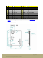
Document Control
Revision
1.0
1.1
Author
RM
MM, PM
Date
23.03.2005
14.11.2005
Note
Initial Release
TinyNode Development Environment Installation
Generic install instructions updated
page 2 of 30
© 2005 All trademarks shown are the property of their respective owners. SH-TNUMAN-101
Table of Contents
Document Control ....................................................................................................................2
Table of Contents.....................................................................................................................3
Introduction ..............................................................................................................................4
TinyNode 584...........................................................................................................................4
Product Summary ................................................................................................................4
Key Features .......................................................................................................................4
Module Overview .................................................................................................................5
Functional Block Diagram ....................................................................................................5
Typical Operating Conditions...............................................................................................6
Power ..................................................................................................................................6
Supply Monitor.....................................................................................................................7
Microcontroller (MSP430F1611) ..........................................................................................7
RF (XE1205)........................................................................................................................7
Antenna Options ..................................................................................................................7
External Flash......................................................................................................................7
Expansion Connector ..........................................................................................................7
Mechanical Characteristics ..................................................................................................7
TinyNode Standard Extension Board .......................................................................................7
Product Summary: ...............................................................................................................7
Key Features .......................................................................................................................7
Module Overview .................................................................................................................7
Functional Block Diagram ....................................................................................................7
Typical Operating Conditions...............................................................................................7
Power ..................................................................................................................................7
Temperature Sensor............................................................................................................7
Light Sensor ........................................................................................................................7
Jumpers (optional) ...............................................................................................................7
Humidity/Temperature Sensor (optional) .............................................................................7
Breadboard and Custom Interfaces .....................................................................................7
RF Extensions (optional)......................................................................................................7
Mechanical Characteristics ..................................................................................................7
Housing Options ..................................................................................................................7
TinyNode Programming and Debugging ..............................................................................7
TinyNode Development Environment Installation.....................................................................7
Manual installation (Generic instructions Windows/Linux) ...................................................7
Part Numbers and Suppliers ....................................................................................................7
Disclaimer ................................................................................................................................7
Contact ....................................................................................................................................7
page 3 of 30
© 2005 All trademarks shown are the property of their respective owners. SH-TNUMAN-101
Introduction
The goal of this manual is to describe the hardware features of the TinyNode module and the
Standard Extension Board.
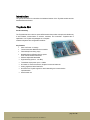
TinyNode 584
Product Summary
The TinyNode 584 is an ultra-low power OEM module that provides a simple and reliable way
to add wireless communication to sensors, actuators, and controllers. TinyNode 584 is
optimized to run TinyOS and packaged as a complete
wireless subsystem with configurable interfaces.
Key Features
• Ultra Low Power 3 V design
•
Texas Instruments MSP430 microcontroller
•
Fast wakeup from sleep (<6µs)
•
868 MHz Xemics XE1205 ultra-low power
multi channel wireless transceiver
•
Software adjustable Bandwidth
•
High sensitivity (down to -121 dBm)
•
Transmitter output power up to +12 dBm
•
On-board 1/4 wave wire antenna, footprint for external antennas
•
Analog, digital and serial interfaces
•
Out-of-the-box TinyOS support for mesh networking and communication
implementation
•
Small: 30x40 mm
page 4 of 30
© 2005 All trademarks shown are the property of their respective owners. SH-TNUMAN-101
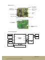
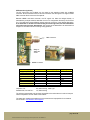
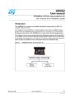
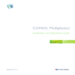
Module Overview
Wire Antenna
mounting hole
MSP430F1611
Microcontroller
MMCX or SMA
(optional)
XE1205
Radio
2.8v Regulator
32kHz crystal
512kB Flash
39MHz crystal
LED
30 pin Expansion
Connector
MMBX RF connector
(optional)
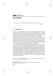
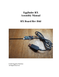
Functional Block Diagram
Temperature
Sensor
(optional)
Supply
Monitor
Regulator
2.8v
EN
P5.4
P6.0
EN
P5.5
P6.1
EN
P5.6
VCC
4
P2[6,7]
P3[4,5]
P1.5
LED
MSP430F1611
10K RAM
48K Flash
P2.0
P2.1
IRQ0
IRQ1
P3.0
P5.7
POR
DATA
SPI
SPI[0]
JTAG
ADC
I/O
I/O
P4.6
P4.7
4
SPI
nRST
nCS
RF
XE1205
Wire
Antenna
MMBX
External
Antenna
STFlash
1024k
Vcc
VReg
30-pin Expansion Connector
page 5 of 30
© 2005 All trademarks shown are the property of their respective owners. SH-TNUMAN-101
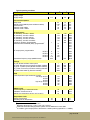
Typical Operating Conditions
Min
Supply voltage:
Supply voltage (VCC or VReg)
Supply voltage during flash memory programming
2.4
2.7
Current Consumptions:
µC sleep with Timer off (LPM4)
µC sleep with Timer on (LPM3)
µC active
µC active, Radio RX
µC active, Radio TX at +0dBm (1mW)
µC active, Radio TX at +5dBm (3.2mW)
µC active, Radio TX at +10dBm (10mW)
µC active, Radio TX at +12dBm (16mW)
µC active, Flash Read
µC active, Flash Write
Temperature Limits:
Storage Temperature
Operating free air temperature
Typ1
4.1
6.5
2.1
16
25
35
46
62
6
17
-40
-40
Max2
UNIT
3.6
3.6
V
V
18.9
21.9
2.6
19
32
42
53
69
12
38
µA
µA
mA
mA
mA
mA
mA
mA
mA
mA
80
80
°C
°C
Power
For battery operation, a TinyNode can be powered directly on VCC using two AA alkaline
cells or one lithium cell. The operating voltage range is from 2.4v to 3.6v DC.
When programming the microcontroller or the external Flash, the voltage has to be at least
2.7v. Below 2.25v, an external reset circuit holds the microcontroller’s reset pin low to avoid
unpredictable behavior at low voltages.
For a stable 2.8v supply, an onboard linear voltage regulator (TPS78928) can be used. In that
case, the board can be powered over VReg ranging from 2.4 to 3.6v DC. Below 2.8v, the
VCC voltage will follow the VReg voltage. For saving power during Stand-By mode, the
regulator needs to be shut down with the nREGE pin connected to P5.6 of the microcontroller.
The microcontroller will still be powered over R16, but it needs to re-enable the regulator after
wake-up and before activating any periphery.
P5.6
The 30-pin Expansion connector described in chapter Expansion Connector provides both
VReg and VCC to the module.
1
2
Typical values at VCC = 3V, T at 25°C
Maximum values at VCC = 3.6V, T from –40°C to 85°C
page 6 of 30
© 2005 All trademarks shown are the property of their respective owners. SH-TNUMAN-101
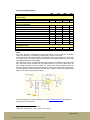
Supply Monitor
The supply voltage can be monitored using the onboard resistive bridge. The nVSUPE should
be configured as an entry on the microcontroller to avoid current flow. To activate the bridge,
it needs to be set as a low-level output pin. The voltage level at VSUP can then be converted
using the following formula: VSUP = VReg*0.239.
P6.1 (ADC)
P5.5
page 7 of 30
© 2005 All trademarks shown are the property of their respective owners. SH-TNUMAN-101
Microcontroller (MSP430F1611)
General
The MSP430 family architecture features five low power modes and is optimized to achieve
extended battery life in portable measurement applications. The MSP430F1611 ultra low
power microcontroller has 10kB of RAM, 48kB of flash, and 128B of memory. It features a
powerful 16-bit RISC CPU with 16-bit registers.
The digitally controlled oscillator (DCO) allows wake-up from low-power modes to active
mode in less than 6µs and may operate up to 8MHz. Typically, the DCO will turn on from
sleep mode in 300ns at room temperature. The MSP430F1611 has two built-in 16-bit timers,
a fast 12-bit A/D converter, dual 12-bit D/A converter, one or two universal serial
synchronous/asynchronous communication interfaces (USART), I2C, DMA, and 48 I/O pins.
Internal Temperature and Voltage Monitoring
The ADC internal ports may be used to read the internal thermistor on ADC port 10 or monitor
the supply voltage (VCC) on ADC port 11. The temperature sensor consists of an
uncalibrated diode that can have a large offset error (up to 20°C). A single point calibration is
recommended for most applications.
Typical Operating Conditions:
Min
Supply voltage
Supply voltage
Supply voltage during flash memory programming
3
1.8
2.7
Current Consumptions
Sleep current, Timer off (LPM4)
Sleep current, Timer 32.768kHz (LPM3)
Αctive current, 1MHz
Αctive current, 4MHz
0.2
2.6
500
2.1
Low Frequency Crystal
Center Frequency
Calibration Tolerance at 25°C
Temperature Coefficient (-40..85°C)
Temperature Limits
Storage Temperature
Operating free air temperature
Typ
Max
UNIT
3.6
3.6
V
V
5.0
8.0
600
2.6
µA
µA
µA
mA
32.768
20
-0.034
-40
-40
4
KHz
ppm
ppm/°C
80
80
°C
°C
For more detailed information, please refer to the datasheet that is available at
http://www.ti.com/msp430
3
4
Typical values at VCC = 3V, T at 25°C
Maximum values at VCC = 3.6V, T from –40°C to 85°C
page 8 of 30
© 2005 All trademarks shown are the property of their respective owners. SH-TNUMAN-101
RF (XE1205)
General:
The XE1205 from XEMICS is an integrated transceiver that can operate in the 433, 868 and
915MHz license-free ISM (Industry Scientific and Medical) frequency bands. The current
design of TinyNode 584 supports European 868MHz operation.
All major RF communication parameters are programmable and most of them can be
dynamically set. The XE1205 offers the unique advantage of narrow-band and wide-band
communication with the same hardware configuration. The XE1205 is optimized for low power
consumption while offering high RF output power.
SRD Band Plan 868…870 MHz
For operation in Europe, the 868MHz band offers several advantages over the 433MHz band:
- Regulated duty cycle ideal for low power sensor applications
- Power levels up to 500mW
- Wide-band and channelized narrow-band operations possible
- Less “crowded” (a lot of toys and keyless entry system work at 433MHz)
Downloads:
ERC/DEC(01)04 decision for SRD bands:
http://www.ero.dk/documentation/docs/docfiles.asp?docid=1463
implementation status for SRD bands:
http://www.ero.dk/documentation/docs/implement.asp?docid=1463
For one channel operation, the standard center frequency setting for a TinyNode is
868.300MHz. Data rates up to 153kbit/s are possible within the 868.000 – 868.600MHz band.
Channel and Bandwidth settings can be configured by software.
It is the responsibility of the programmer to respect duty cycle and power regulations for his
application.
page 9 of 30
© 2005 All trademarks shown are the property of their respective owners. SH-TNUMAN-101
Typical operating conditions
Min
Supply voltage:
Supply voltage
Typ5
2.4
Current Consumptions
Sleep mode
Standby mode (39MHz quartz oscillator enabled)
Receive mode
Transmit mode +5dBm
Transmit mode +15dBm
RF performance
RF Sensitivity, A-mode, 1.2kbit/s
RF Sensitivity, A-mode, 4.8kbit/s
RF Sensitivity, A-mode, 19kbit/s
RF Sensitivity, A-mode, 76.2kbit/s
RF Sensitivity, A-mode, 152.3kbit/s
Frequency deviation, programmable
Base band filter bandwidth (SSB), programmable7
Max6
UNIT
3.6
V
0.2
0.85
14
33
62
1.0
1.1
16.5
40
75
µA
mA
mA
mA
mA
-121
-116
-110
-104
-101
-118
-113
-107
-101
-98
255
dBm
dBm
dBm
dBm
dBm
kHz
kHz
kHz
kHz
kHz
1
10
20
40
200
RF output power, programmable
RFOP1
RFOP2
RFOP3
RFOP4
Synthesizer frequency range (868MHz band)
-3
+2
+7
+12
863
0
+5
+10
+158
870
dBm
dBm
dBm
dBm
MHz
Timings
TS_OS: Quartz oscillator wake-up time
TS_SRE: RX wake-up time (Quartz oscillator enabled)
TS_STR: TX wake-up time (Quartz oscillator enabled)
TS_TFSW: TX recovery time when switching channels
TS_RSSI: RSSI wake-up (Receiver enabled)
1
700
250
150
2/BR
RSSI
VTHR, Equivalent input thresholds (A-mode)
low range: VHTR1
VHTR2
VHTR3
high range: VHTR1
VHTR2
VHTR3
-110
-105
-100
-95
-90
-85
dBm
dBm
dBm
dBm
dBm
dBm
39
15
20
MHz
ppm
ppm
39MHz Crystal
Center Frequency, Fundamental mode
Calibration Tolerance at 25°C
Stability over temperature range (-40°C to 85°C)
Temperature Limits
Storage Temperature
Operating free air temperature
-40
-40
2
850
350
250
80
80
ms
µs
µs
µs
ms
°C
°C
5
Typical values at VCC = 3V, T at 25°C
Maximum values at VCC = 3.6V, T from –40°C to 85°C
7
Additional bandwidth settings possible, please consult datasheet for more detail
8
At +15dBm, typical output power of the board is +12dBm (matching optimal for 0..+10dBm)
6
page 10 of 30
© 2005 All trademarks shown are the property of their respective owners. SH-TNUMAN-101
For more detailed information, please refer to the datasheet that is available at
http://www.xemics.com
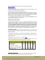
Changing the data rate:
The XE1205 can be programmed for wide band (higher data rate, lower bandwidth) or narrow
band (lower data rate, higher range) communication.
Please consider the following when changing the data rate:
1) The TinyNode is a very flexible module because of the configurable parameters it supports.
However, modules that are not configured in the same way will not be able to communicate
reliably, causing poor performance or failure of the wireless link. All modules in a network
must have the same mode configuration to ensure interoperability.
2) The transmitters frequency deviation and the receivers filter bandwidth have to be
set according to the data rate. As a rule of thumb:
FREQ_DEV [kHz] > Data Rate [kbit/s]
RX_BW [kHz] > FREQ_DEV [kHz] * 2
3) The 39 MHz crystal frequency tolerance of +/- 20ppm directly translates into a RF center
frequency tolerance of 20ppm or +/- 18kHz at 868 MHz. This means that the maximum
misalignment at room temperature between a sending and a receiving node can be 2*18kHz
= 36 kHz. If the nodes are at different temperatures, you have to add the temperature drifts as
well. If the misalignment of the sender’s and the receiver’s frequency is bigger than the
frequency deviation of the sender, a link will not be possible. In that case, the FEI
function (frequency error indication) of the XE1205 can be used in order to compensate the
frequency offset. Please refer to the datasheet for a detailed description of this feature.
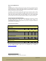
Link budgets and Range:
A link budget is the best figure for comparing range performances. To calculate the link
budget for a wireless link, simply add the transmit power and the antenna gains, then subtract
the receiver sensitivity:
LinkBudget[dB] = TXpower[dBm] + TXAntGain[dBi] + RXAntGain[dBi] – RXSensitivity[dBm]
For example, the typical link budget for a pair of TinyNodes at +10dBm, 76kbit/s with ¼ wave
whip antennas will be:
LinkBudget[dB] = 10dBm + 0dBi + 0dBi – (-104dBm) = 114 dB
A link budget of 114dB easily yields a range of 200m or more outdoors and 40m or more
indoors. Following table gives an overview with typical data rate settings:
DataRate
152.3
76.2
9.6
1.2
kbit/s
Receiver Bandwidth
Receiver Sensitivity
Transmit Power
Transmit Frequency deviation
400
-101
10
100
200
-104
10
80
20
-113
10
10
7
-121
10
2
kHz
dBm
dBm
kHz
Link Budget with ¼ wave whip antenna
Typical Range, outdoor, Line of Sight
Typical Range, indoor9
110
150
30
114
200
40
123
600
80
131
1800
200
dB
m
m
9
Indoor range will depend largely on the structure of the building and the number of walls the
signal needs to pass through. Figures above are for typical office environments.
page 11 of 30
© 2005 All trademarks shown are the property of their respective owners. SH-TNUMAN-101
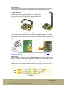
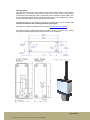
Antenna Options
Care should be taken to the antenna configuration in order to get the best range performance.
Any degradation in the antenna gain will directly diminish the link budget and the range.
¼ wave wire antenna
The TinyNode module is supplied with a ¼ wave monopole wire
antenna that gives good performance when the wire is kept straight
or bent with enough distance from any electrical mass (see
configurations below). As a rule of thumb, the antenna should not
be bent any closer than 20mm to the PCB board.
MMBX or SMA antenna connectors (optional)
The back side of the TinyNode PCB allows to solder a SMT MMBX connector for connection
of an external antenna or board-to-board connection of the RF signal. Another option is to
mount a SMA connector at the edge of the board (see photos). Both connectors need to have
50 Ohms impedance. For hand mounting, the MMBX connector needs to be soldered with hot
air.
The exact part numbers and suppliers for the connectors can be found in chapter Part
Numbers and Suppliers.
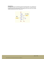
External Flash
TinyNode features a 4-Mbit serial flash (Atmel AT45DB041) for external data and code
storage. The flash holds 512kB of data and is decomposed into 2048 pages of 264
Bytes/Page. Both page and block erase operations are supported.
The flash shares SPI communication with the XE1205 transceiver. Care must be taken
when reading or writing to flash while communicating over the radio. This can be done with a
software arbitration protocol for the SPI bus on the microcontroller.
P3.1
P3.3
P4.6
P4.7
P3.2
page 12 of 30
© 2005 All trademarks shown are the property of their respective owners. SH-TNUMAN-101
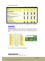
Typical operating conditions
Min
Supply
Supply voltage during flash memory programming
2.5
Current Consumptions
Stand-By current
Active current READ
Active current PROGRAM / ERASE
2
4
15
Timings
Page Erase and Programming Time
Page Programming Time
Page Erase Time
Block Erase Time
Temperature Limits
Storage Temperature
Operating free air temperature
Typ10
-40
-40
Max11
UNIT
3.6
V
10
10
35
µA
mA
mA
20
14
8
12
ms
ms
ms
ms
80
80
°C
°C
For more detailed information, please refer to the datasheet that is available at
http://www.atmel.com
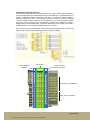
Expansion Connector
The expansion connector provides a user interface for sensor boards and base stations. The
connector includes interfaces for power and ground, JTAG for programming and debugging,
ADC inputs and DAC outputs, UART and SPI interfaces, general-purpose digital IO and
others.
Connector mounted on TinyNode: Molex Part No 52465-3071
10
11
Typical values at VCC = 3V, T at 25°C
Maximum values at VCC = 3.6V, T from –40°C to 85°C
page 13 of 30
© 2005 All trademarks shown are the property of their respective owners. SH-TNUMAN-101
Pin
1
3
5
7
9
11
13
15
17
19
21
23
25
27
29
Name
TDO
TDI
TMS
TCK
URXD1
UTXD1
P1.2
P1.3
E_EVREF
P6.7
P6.6
P6.5
P6.4
P6.3
P6.2
I/O
O
I
I
I
I/O
I/O
I/O
I/O
I
I/O
I/O
I/O
I/O
I/O
I/O
Description
JTAG, TDO
JTAG, TDI
JTAG, TMS
JTAG, TCK
P3.7, URXD1
P3.6, UTXD1
P1.2, TA1
P1.3, TA2
External Voltage Ref
P6.7, ADC7, DAC1
P6.6, ADC6, DAC0
P6.5, ADC5
P6.4, ADC4
P6.3, ADC3
P6.2, ADC2
Pin
2
4
6
8
10
12
14
16
18
20
22
24
26
28
30
Name
VCC
VReg
GND
nRST
nREGE
STE1
SIMO1
SOMI1
UCLK1
P1.6
P2.3
P2.4
P4.0
P4.1
E_IVREF
I/O
I
I/O
I/O
I/O
I/O
I/O
I/O
I/O
I/O
I/O
I/O
O
Description
Direct Supply (no regulator)
Supply to 2.8v regulator
Ground
Reset (active low)
P5.6, Regulator Enable
P5.0, SPI STE1
P5.1, SPI SIMO1
P5.2, SPI SOMI1
P5.3, SPI UCLK1
P1.6, TA1
P2.3, CA0, TA1
P2.4, CA1, TA2
P4.0, TB0
P4.1, TB1
Internal Voltage Ref
The part numbers and suppliers for the mating connectors can be found in Part Numbers and
Suppliers.
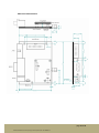
Mechanical Characteristics
page 14 of 30
© 2005 All trademarks shown are the property of their respective owners. SH-TNUMAN-101
TinyNode Standard Extension Board
Product Summary:
The Standard Extension Board adds power supply; interfaces and sensors to TinyNode™
embedded wireless network nodes.
Key Features
• Mates with TinyNode™ via 30-pin expansion connector and optional MMBX board-toboard HF connector
•
On Board Light and Temperature Sensor
•
Footprint for Sensirion™ Humidity Sensor
•
Easy integration with a wide variety of sensors and actuators
•
LEDs and Jumpers
•
JTAG and RS232 Connectors
•
20-pin extension connector (IDC pin-through-hole connector)
•
mini breadboard for custom interfaces
•
Footprint for 50 Ohm SMA connector
•
Delivered with external power supply and connector for battery pack.
•
Size: 74x60 mm
•
Fits housing from Hammond Manufacturing
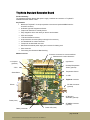
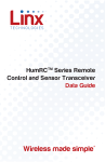
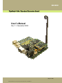
Module Overview
Extension Connector for custom interfaces
Breadboard for custom electronics
Light Sensor
4 x Jumpers
(optional)
Humidity/Temperature
Sensor (optional)
JTAG
Temperature Sensor
Reset Button
3 x LED
TinyNode Connector
RS232
RF SMA Connector
(optional)
RF Bridge or
Attenuator (optional)
Power (Jack)
RF MMBX Connector
(optional)
Battery Connector
Power LED (Jack)
page 15 of 30
© 2005 All trademarks shown are the property of their respective owners. SH-TNUMAN-101
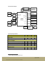
Functional Block Diagram
Breadboard for
custom wiring
12
5
JTAG
RS232
4
Level
Shifter
Reset
Logic
8
P1.6
P2.3
P2.4
JTAG
URXD1, BRX
UTXD1, BTX
red LED
green LED
yellow LED
P6.4 (ADC4)
P1.3
P6.5 (ADC5)
TCK
nRST
TinyNode
Expansion
Connector
Reset Button
20-pin Extension
Connector for
custom interfaces
P4.0
P4.1
Light Sensor
EN
SCK
3.0v
Regulator
Humidity Sensor
(optional)
ADC Reference
(optional)
E_EVREF
Power
Jack
Temperature Sensor
DATA
VCC
P5[0..3]
4
MMBX
(RF)
RF Bypass or
Attenuator
(optional)
Jumpers (optional)
Battery
SMA
(RF)
Typical Operating Conditions
Min
Supply voltage
Supply voltage over Power Jack
Supply voltage over Battery Pack
4
5
see TinyNode section
Current Consumption
on any RS232 pin12
Temperature Sensor, Active Mode (while reading)
Humidity Sensor, Sleep Mode
Humidity Sensor, Active Mode (while reading)
External DC Reference, Active Mode
Temperature Limits
Storage Temperature
Operating free air temperature
12
Typ
110
0.3
550
0.8
-40
-40
Max
UNIT
12
V
2
210
1
1.2
mA
µA
µA
µA
mA
80
80
°C
°C
Used to supply Level Shifter and Reset Logic
page 16 of 30
© 2005 All trademarks shown are the property of their respective owners. SH-TNUMAN-101
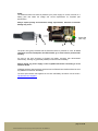
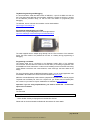
Power
The Extension Board can either be powered by AC power supply via a Jack connector or a
battery pack that meets the voltage and current requirements for TinyNode (see
specification).
Always respect polarity and maximum voltage requirements, otherwise irreversible
damage may occur!
Power LED
(Jack only)
-
+
+
-
The power LED (green) indicates that the Extension Board is powered via Jack. To avoid
continuous current consumption, the LED will NOT go on if the board is powered with
a battery.
As soon as the Jack connector is plugged, the battery connector gets disconnected
mechanically, avoiding any (potentially harmful) current flow into the battery.
Always unplug any power supply on the TinyNode itself before connecting it to the
extension board.
All RS232 interface parts are directly powered from the RS232 line and will therefore not draw
any additional current from the battery.
The exact part numbers and suppliers for the Jack and Battery connectors can be found in
Part Numbers and Suppliers.
page 17 of 30
© 2005 All trademarks shown are the property of their respective owners. SH-TNUMAN-101
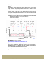
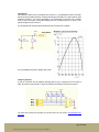
Temperature Sensor
The temperature sensor on the extension board used is the LM20 from National
Semiconductor with an operating range from –55°C to 130°C. The typical accuracy is +/1.5°C at ambient room temperature. However, if the internal voltage reference from the
MSP430F1611 is used, its tolerance needs to be taken into account and will add typically +/5°C of error over different supply voltages. Use a calibration point or an external voltage
reference to compensate this error.
P1.3
P6.5 (ADC5)
The sensor needs to be enabled by setting EX_TEMPE (P1.3) before doing a measurement.
After a settle time of 500µs, the result can be read at channel 5 from the microcontrollers
ADC. Figure below shows typical output voltage as a function of temperature. To get the
voltage level at the ADC input pin, this voltage needs to be divided by 2 (resistive
divider).
For more detailed information, please refer to the datasheet that is available at
http://www.national.com/pf/LM/LM20.html
page 18 of 30
© 2005 All trademarks shown are the property of their respective owners. SH-TNUMAN-101
Light Sensor
The Extension Board uses a photodiode from Infineon™, Type BPW34S–P1602. The diode
senses the entire visible spectrum including infrared light from 400nm to 1100nm with its peak
sensitivity at 850nm. The current generated by the photodiode is converted into a voltage
level via R16. The output will provide voltages from 0V (complete dark) up to around 1.2V
(direct sunlight) at ADC channel 4.
Any photodiode with similar physical dimensions may be used with TinyNode.
P6.4 (ADC4)
For more detailed information, please refer to the datasheet that is available at datasheet?
Jumpers (optional)
A 4X2 pin connector can be soldered optionally (K8) to get 4 Jumpers that can be read at
P5[0..3] from the microcontroller. The pull-up resistors are already mounted on the board.
P5.0
P5.1
P5.2
P5.3
The exact part number and supplier for the Connector can be found in Part Numbers and
Suppliers.
page 19 of 30
© 2005 All trademarks shown are the property of their respective owners. SH-TNUMAN-101
Humidity/Temperature Sensor (optional)
The humidity/temperature sensor SHT11 or SHT15 can be mounted on the board at the U10
component position. You will also need to mount resistor R43 (10k, 1%, 0603) and capacitor
C21 (100nF, 0603).
The SHT11/SHT15 sensors have their calibration coefficient stored in the sensors onboard
EEPROM. The SHT15 produces higher accuracy results than the SHT11. It provides a digital
output that can be read via the HUM_DATA (connected to port P4.0) and the HUM_SCK
(connected to port P4.1) pins.
P4.0
P4.1
For more detailed information, please refer to the datasheet that is available at
http://www.sensirion.com
page 20 of 30
© 2005 All trademarks shown are the property of their respective owners. SH-TNUMAN-101
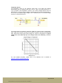
Breadboard and Custom Interfaces
The extension board features a breadboard that can be used to realize simple interfaces to
custom sensors and/or other peripherals that may be controlled by the TinyNode module. It is
a field of pads with standard 2.54mm pitch that has on one side 14 pads connected to
different TinyNode I/O’s and on the other side 12 pads connected to the 20-pin extension
connector. Simple interface electronics can be soldered on the unconnected pads between
those rows. The 8 remaining pins on the extension connector are “hardwired” to realize a
simple interface without soldering any components. Depending on the number of pins used, a
smaller connector can be soldered instead of the 20-pin connector.
Since some of the pins are shared with other electronics (see diagram below), care must be
taken in order to ensure that the additional electronics does not interfere.
14 pads routed to
TinyNode
unconneted
12 pads routed to
extension connector
Pin[9..20] from breadboard
Pin[1..8] from TinyNode
page 21 of 30
© 2005 All trademarks shown are the property of their respective owners. SH-TNUMAN-101
RF Extensions (optional)
The RF signal from the TinyNode can be routed to the extension board with a MMBX
connector. On the extension board, a 50 Ohm PCB trace routs the signal to an edge mounted
SMA connector. Both connectors are optional.
Between MMBX and SMA connector, the RF signal can either be bridged directly or
attenuated by a simple resistive attenuator circuit in PI configuration formed by R9, R10 and
R11. The table below shows different resistor values as a function of the desired attenuation.
If an attenuator is mounted on both sending and receiving board, the total attenuation
will be the sum of the two attenuations! The purpose of the attenuator is to reduce the link
budget in a controlled manner for testing routing protocols.
SMA Connector
Bridge or
Attenuator
Circuit
MMBX Connector
Attenuation [dB]
0 (bypass)
5
10
15
20
25
30
35
40
Capacitor C32:
Resistors R9, R10 and R11:
C32 [pF]
33
33
33
33
33
33
33
33
33
R10, R11 [Ohm]
not mounted
178.5
96.2
71.6
61.1
56
53.3
51.8
51
R9 [Ohm]
0
30.4
71.2
136.1
247.5
443.2
789.8
1405
2500
5%, 0603 housing, COG Type
1%, 0603 housing
The values mounted need to be as close as possible to the values above in order to keep 50
Ohms of impedance on both sides of the network.
The exact part numbers and suppliers for the connectors and a proposition for an antenna
can be found in Part Numbers and Suppliers.
page 22 of 30
© 2005 All trademarks shown are the property of their respective owners. SH-TNUMAN-101
Mechanical Characteristics
The board can either be mounted with 3 x M3 screws or it can be slit into a housing (see
chapter Housing Options). 6mm spacers can be used to get a robust mechanical assembly
between TinyNode and the extension board.
page 23 of 30
© 2005 All trademarks shown are the property of their respective owners. SH-TNUMAN-101
Housing Options
For indoor use, the extension board can be slid into a series 1455J housing from “Hammond
Manufacturing”. The housing comes with two options for the front panel: a plastic version
(1455J1201) and an aluminum version (1455J1202). We recommend using the plastic cover
for the Front Panel (RS232, Power) and the Aluminum cover for the back panel (RF output).
The aluminum panel will act as a ground plane for the antenna.
The standard length of the housing is 120mm, but custom length can be ordered. The
extension board will fit into a housing with 63mm body length.
The exact part numbers and suppliers can be found in Part Numbers and Suppliers.
The 1455J housings are IP54 protected and for indoor use only. For outdoor use, a plastic
housing with screwed cable glands and IP67 protection is recommended.
page 24 of 30
© 2005 All trademarks shown are the property of their respective owners. SH-TNUMAN-101
TinyNode Programming and Debugging
It is recommended to install the latest version of MSPGCC, a port of the GNU tool chain for
the Texas Instruments MSP430 microcontrollers. MSPGCC includes an efficient C compiler
for the MSP430 processor family, as well as tools and utilities for programming and
debugging.
The software, source code and documentation can be downloaded at
http://mspgcc.sourceforge.net
Programming and debugging over JTAG:
MSP430 FETP programming adaptors can be bought online at
http://www.softbaugh.com/ProductPage.cfm?strPartNo=FETP
The cable supplied with the adaptor plugs directly into the JTAG connector of the extension
board. The board needs to be powered via the Jack or a battery during programming or
debugging.
Programming over RS232:
The RS232 serial port is connected to the Bootstrap Loader (BSL) of the MSP430
microcontroller. RTS and DTR are routed to TCK and nRST pin according to application note
SLAA096B from Texas instruments. In order to avoid resetting the microcontroller when doing
normal RS232 connections and communications, some reset logic has been added to the
design.
For more information about the MSP430 Bootstrap Loader, you can consult application note
SLAA096B or SLAA089A from Texas Instruments available at www.ti.com.
MSPGCC includes Bootstrap Loader software (msp430-bsl.exe) that can be used to program
TinyNode over the RS232 port. Since it is a Python tool, you will also need to install Python
2.0 or newer on your machine. Python installations are available at www.python.org
Important: if you are using msp430-bsl.exe, you need to include the “--invert-reset”
option in the command.
Example:
The command
C:\mspgcc\bin>msp430-bsl –epI –-invert-reset file.ihex
…Clears all flash memory and programs the IntelHex file “file.ihex”
Please refer to the documentation available with the software for more details.
page 25 of 30
© 2005 All trademarks shown are the property of their respective owners. SH-TNUMAN-101
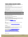
TinyNode Development Environment Installation
The goal of this chapter is to give you a quick guide of how to download and install necessary
components to develop for TinyNode using TinyOS.
Automated installation (Windows)
The automatic installer let you easily deploy the development environment on your computer.
It comes with all the necessary components and do not assume any prerequisite to be
installed on your computer.
The installer enables you to select which component you would like to install. We recommend
selecting all components.
After the installation procedure has completed, you can start the Cygwin shell by clicking on
the TinyNode icon on you desktop. The last task is to build the java tools; at the shell prompt
type:
cd $TOSROOT/tools/java; make; make
Then, move to the Shockfish directory and compile the TinyNode-specific java tools:
cd $TOSROOT/contrib/shockfish/tools/java; make
Please remember to keep your TinyOS sandbox up-to-date. To do so, please read the
TinyOS CVS Repository section below.
Manual installation (Generic instructions Windows/Linux)
Cygwin (for Microsoft Windows only):
Cygwin is a Linux-like environment for Windows that is used as the development environment
for TinyOS. It is recommended to install all the packages (the ones selected by default will not
be sufficient), but you can also install them manually as needed.
Cygwin documentation: www.cygwin.com
Cygwin download and install: www.cygwin.com/setup.exe
Java:
PC tools that come with TinyOS will use Java. TinyOS tools are tested on Java 2 Platform,
SE 1.4.2 (J2SE).
Java SDK download and install: http://java.sun.com/j2se/1.4.2/download.html
JavaComm:
This is an additional package for Java needed to access the serial port on your computer.
TinyOS CVS Repository:
SourceForge hosts the TinyOS CVS repository. The code in the /contrib./shockfish folder
contains platform definitions and modules that are TinyNode specific.
TinyOS CVS installation guide: http://sourceforge.net/cvs/?group_id=28656
Browse CVS TinyOS: http://cvs.sourceforge.net/viewcvs.py/tinyos/
Browse CVS TinyOS, shockfish contributions:
http://cvs.sourceforge.net/viewcvs.py/tinyos/tinyos-1.x/contrib/shockfish/
Please keep your repository up-to-date and check for new updates regularly.
MSPGCC Toolchain:
page 26 of 30
© 2005 All trademarks shown are the property of their respective owners. SH-TNUMAN-101
This is the GCC toolchain for MSP430 microcontrollers. Includes the GNU C compiler (gcc),
the assembler and linker (binutils), the debugger (gdb) and some other tools needed to make
a development environment for the MSP430.
For download and install, we recommend using the build-mspgcc script in
http://cvs.sourceforge.net/viewcvs.py/tinyos/tinyos-1.x/tools/src/mspgcc
The script will download and install the latest version that will also support the relatively new
MSP430F1611 processor.
If you prefer to do things manually, follow the instructions at
mspgcc homepage: http://mspgcc.sourceforge.net
mspgcc for Windows: http://sourceforge.net/project/showfiles.php?group_id=42303
mspgcc for Linux: http://mspgcc.sourceforge.net/manual/c1686.html#shopping-list
NesC:
NesC is the programming language used for TinyOS and it requires its own front-end
compiler to be installed.
nescc homepage: http://nescc.sourceforge.net
nescc download: http://sourceforge.net/projects/nescc
NesC assumes the use of the Mica platform and tries to compile a new assembler for the
Atmel avr processors, which is not needed if you work with TinyNodes. If you want to avoid
this stage, you can type the following command into the shell prompt:
perl -i.orig -pe 's{\S+avr-as[^\s"]+}{}g if /^\s*ac_config_f/; $_=""
if /avr-as/;' Makefile.in configure{,.in} tools/Make*
Environment:
In order to be able to start compiling and executing code, you need to set your environment
variables correctly. As the variables slightly differ depending on your platform, a Windows and
a Linux listing are provided below.
# TinyNode environment – Windows/Cygwin
# Java
export JDKROOT=/cygdrive/c/j2sdk1.4.2_05
export PATH="$JDKROOT/bin:$PATH"
# MSPGCC
export MSPGCCROOT=/cygdrive/c/mspgcc
export PATH="$MSPGCCROOT/bin:$PATH"
# TinyOS
export TOSROOT=$HOME/tinyos-1.x
export TOSDIR=$TOSROOT/tos
CLASSPATH="`$TOSROOT/tools/java/javapath`"
export CLASSPATH="`cygpath -w $TOSROOT/contrib/shockfish`;$CLASSPATH
# building TinyNode
export TOSMAKE_PATH="$TOSDIR/../contrib/shockfish/tools/make"
export MAKERULES=$TOSROOT/tools/make/Makerules
page 27 of 30
© 2005 All trademarks shown are the property of their respective owners. SH-TNUMAN-101
# TinyNode environment – Linux
# Java
export JDKROOT=/opt/j2sdk1.4.2_05
export PATH="$JDKROOT/bin:$PATH"
# MSPGCC
export MSPGCCROOT=/opt/mspgcc
export PATH="$MSPGCCROOT/bin:$PATH"
# TinyOS
export TOSROOT=$HOME/tinyos-1.x
export TOSDIR=$TOSROOT/tos
CLASSPATH="`$TOSROOT/tools/java/javapath`"
export CLASSPATH=$TOSROOT/contrib/shockfish:$CLASSPATH
# building TinyNode
export TOSMAKE_PATH="$TOSDIR/../contrib/shockfish/tools/make"
export MAKERULES=$TOSROOT/tools/make/Makerules
TinyOS Java Tools:
The TinyOS Java tools require the MIG utility provided by NesC to generate some source files
for processing messages. Unfortunately, MIG assumes that avr-gcc has been installed on
your system. To overcome this issue, you should first patch the toolchain:
cd ${TOSROOT}/..
wget http://www.shockfish.com/tinynode/patches/tinynode-mig.patch
patch -p0 < tinynode-mig.patch
You can now compile all the Java tools at once using the following command:
cd $TOSROOT/tools/java; make; make
Finally, compile the Shockfish-specific tools:
cd $TOSROOT/contrib/shockfish/tools/java; make
page 28 of 30
© 2005 All trademarks shown are the property of their respective owners. SH-TNUMAN-101
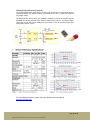
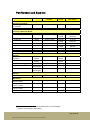
Part Numbers and Suppliers
Part Description
Manufacturer
Manufacturer Part
Number
Supplier
for CH
Supplier
Part Number
Connectors TinyNode
30pin extension connector
on TinyNode
…mates with
Molex
52465-3071
EME
52465-3071
Molex
53364-3071
EME
53364-3071
Connectors Extension Board
20pin expansion connector
…mates with
Harting
Harting
0918-520-6324
0918-520-7803
14pin JTAG connector
…mates with
Harting
Harting
0918-514-6323
0918-514-7803
Battery connector
…mates with
Molex
Molex
53398-02
51021-02
CUI Inc
CUI Inc
Harwin
PJ-102A
10.665
M20-9980405
Farnell
Distrelec
Farnell
Farnell
Distrelec
Farnell
Farnell
Farnell
Farnell
Digi-Key
Distrelec
Farnell
864-717
12 28 36
302-2146
864-778
12 28 32
302-2122
889-374
889-477
889-570
CP-102A-ND
15 13 06
512-114
Huber &
Suhner
Huber &
Suhner
Johnson
Linx
Technologies
Linx
Technologies
82_MMBX-S50-0-1
23001785
J502-ND
CONREVSMA003.062
Huber &
Suhner
Huber &
Suhner
Digi-Key
Digi-Key
J502-ND
CONREVSMA003.062
ANT-868-CW-QW
Digi-Key
BH2AA-W-ND
Sensirion
SHT11 or SHT15
Farnell
391-3065
Richco
MSPM-4-01
Distrelec
34 04 96
Hammond
1455J1201
Farnell
427-2833
Hammond
1455J1202
Farnell
427-2950
Hammond
1455J
Sibalco14
1455J, 63mm
Power Jack connector
…mates with
4x2 Jumper Array
RF parts
MMBX Connector for
Tinynode
…mates with
SMA connector
RP-SMA connector13
868MHz external antenna
Sensors
Humidity Sensor
Mechanical
Spacers for 3.2mm hole,
6.4mm stacking
Housing, plastic panel
version, 120mm
Housing, aluminum panel
version, 120mm
Housing, 63mm length
13
14
81_MMBX-S50-0-1
23001782
use this connector to add an external antenna from Linx Technologies
minimum order quantity of 25pce apply
page 29 of 30
© 2005 All trademarks shown are the property of their respective owners. SH-TNUMAN-101
Disclaimer
Shockfish SA believes the information contained herein is correct and accurate at the time of
this printing. However, Shockfish SA reserves the right to make changes to this product
without notice. In no event shall Shockfish SA be liable for any damages (whether special,
incidental, consequential or otherwise), regardless of under what legal theory, tort, or contract
such damages may be alleged (including, without limitation, any claims, damages, or liabilities
for loss of business, profits, business interruption, loss of business information, or for injury to
person or property) arising out of the use or inability to use the product described in this
document.
This product is not designed for use in life support devices or any other system where
malfunction can reasonably be expected to result in significant personal injury to the user.
The product is not designed for critical systems where failure of the product to perform affects
safety or effectiveness. Shockfish SA customers using or selling products for use in such
applications do so at their own risk and agree to fully indemnify Shockfish SA for any
damages resulting from improper use or sale.
Contact
Document download:
E-mail:
Technical Support E-mail:
http://www.tinynode.com/tinynode
[email protected]
[email protected]
Shockfish SA
PSE-C Parc Scientifique
1015 Lausanne EPFL
Phone: +41 21 693 85 15
Fax:
+41 21 693 85 16
page 30 of 30
© 2005 All trademarks shown are the property of their respective owners. SH-TNUMAN-101