1
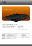
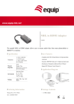
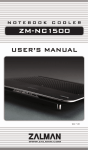
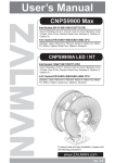
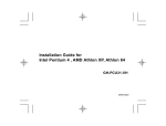
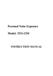
User’s Manual
CNPS9900 series
Intel Socket 1366/1156/775 CPU
Core i7
Core 2 Quad
Core 2 Duo
Core 2 Extreme
Dual Core Pentium
Pentium D
Pentium 4
Celeron D
AMD Socket AM3/AM2+/AM2/754/939/940 CPU
Phenom Ⅱ
Phenom
Athlon 64 FX
Athlon 64 X2 Dual-Core
Athlon 64
Opteron
Opteron Dual-Core
Sempron
To ensure safe and easy installation,
please read the following precautions.
http://www.zalman.com
Ver. 1.0
1. Precautions
1)
2)
Use and keep product away from reach of children and pets.
Do not ingest the Thermal Grease, and avoid its contact with skin and
eyes. If contact is made with skin, wash off with water. If ingested or
irritation persists, seek medical attention.
3) To prevent possible injuries, gloves must be worn while handling this
product.
4) Excessive force exerted on the fan may cause damage to the fan and/
or system.
5) Avoid inserting objects or hands into the fan while it is in operation to
prevent product damage and injuries.
6) Check the components list and condition of the product before
installation. If any problem is found, contact the retailer to obtain a
replacement.
7) Zalman Tech Co., Ltd. is not responsible for any damages due to
overclocking.
8) During transportation of the system, the cooler must be removed.
Zalman is not responsible for any damages that occur during the
transport of a system.
9) Product design and specifications may be revised to improve quality
and performance.
Disclaimer) Zalman Tech Co., Ltd. is not responsible for any damages due
to external causes, including but not limited to, improper use,
problems with electrical power, accident, neglect, alteration,
repair, improper installation, or improper testing.
2. Specifications
Model
Spec.
Materials
CNPS9900A LED
CNPS9900 NT
Pure Copper
Pure Copper/
Black-Pearl Nickel
Plated
Weight
730g
Dimensions
94(L) x 131(W) x 152(H)㎜
Heat Dissipation Area
5,402㎠
Bearing
2 Ball-Bearing
Main Functions
LED Color
Fan
without
RC33P
with
RC33P
Thermal
Grease
(ZM-STG2)
RPM
PWM Control / Auto Restart
Blue
Green
1,000 ~ 2,000rpm ±10%
Noise Level
19.5 ~ 38.0dBA ±10%
RPM
800 ~ 1,300rpm ±10%
Noise Level
18 ~ 28.5dBA ±10%
Contents
3.5g
Temperature Range
-40℃ ~ +150℃ (-40℉ ~ +302℉)
.COM
1
3. Components
1) Common Components
Thermal Grease
(ZM-STG2)
Cooler
Washers
Resistor Cable
(RC33P)
User’s Manual
2) Intel Socket 1156/775 Components
Socket 1156/775 Clip
Socket 1156 Nuts
Socket 1156/775
Clip Support
Socket 775
Backplate
Bolts (Silver)
3) Intel Socket 1366 Components
Socket 1366 Clip
Socket 1366
Clip Support
Bolts (Gold)
4) AMD Socket AM3/AM2+/AM2/754/939/940 Components
AMD Clip
AMD Clip Lever
.COM
2
4. Installation Requirements
1) Space Requirements
The cooler’s installation requires unobstructed space with dimensions of
133mm(width), 154mm(length), 96mm(height), and the CPU as a central
reference point. Please check if components such as ODDs and PSU protrude
into the required space.
2) Air Guide Removal
Air guides on enclosures must be removed, before the cooler’s installation, for
they protrude into the cooler’s required space.
96㎜
154㎜
133㎜
3) Protective Brace Removal
Please unclip and remove the heatsink’s Plastic Brace before installing the cooler.
The Plastic Brace is in place to protect the cooler during transport.
4) Cooler Orientation
In relation to the cooler’s centrally located fan, air flows from the “thinner”(front) heatsink
to the “thicker”(rear) heatsink. As shown in the diagram below, it is recommended that
the cooler be installed so that air flows from the cooler toward the enclosure’s rear
exhaust fan to be released.
Rear Side
Front Side
Enclosure’s (Rear) Exhaust
PSU
VGA slot
.COM
3
5) Handling the Cooler
Please hold the cooler with
both hands as shown in the
diagram.
5. Installation
1) Intel Socket 1156/775 and Socket 1366 Installation
① - A Socket 775 Clip Support Installation
Bolt (Silver)
Socket 1156/775
Clip Support
M/B
Socket 775 Backplate
① - B Socket 1156 Clip Support Installation
Bolt (Silver)
Socket 1156/775
Clip Support
Washer
M/B
Socket 1156 Nut
.COM
4
① - C Socket 1366 Clip Support Installation
Socket 1366 Clip Support
Washer
M/B
Bolt (Gold)
② Clear off any particles or
residue from the CPU’s
surface then spread
(outwards from center) a
thorough layer of Thermal
Grease on the CPU and the
base of the cooler.
③ First insert the Socket 1156/775 Clip or Socket 1366 Clip at a slanted
angle and center the Clip on top of the cooler’s Base Cover.
.COM
5
④ Making sure that the cooler and the clip are centered, securely fasten
the clip by tightening the Intel Socket 1156/755 or Socket 1366 Clip
Fixing Bolts. Please tighten each Fixing Bolt one rotation at a time until
all are completely tightened.
Warning
Make sure the Clip is centered for flush installation.
⑤ Connect the cooler’s 4-pin connector to the motherboard’s CPU Fan
header.
Tip
The Resistor Cable (RC33P) is provided for users seeking ultra quiet
operation. Connecting the Resistor Cable as shown in the diagram will set
the cooler in Quiet Mode.
RC33P
M/B
M/B
Warning
After installation, PWM Control Mode must be activated in the
motherboard’s BIOS.
.COM
6
2) AMD Socket AM3/AM2+/AM2/754/939/940 Installation
① Clear off any particles or residue
from the CPU’s surface then
spread (outwards from center)
a thorough layer of Thermal
Grease on the CPU and the base
of the cooler.
② Install the AMD Clip onto the cooler as shown in the diagram below.
③ P
lace the cooler on the center of the CPU. Align and connect the Clip’s
Lug Slot with the Lug of the motherboard’s retention frame. Press onto the
Clip Lever when aligning the Lever’s Lug Slot with the Lug.
Lug Slot
AMD
Clip Lever
AMD Clip
3
1
2
.COM
Lug
7
④ Connect the cooler’s 4-pin connector to the motherboard’s CPU Fan
header.
Tip
The Resistor Cable (RC33P) is provided for users seeking ultra quiet
operation. Connecting the Resistor Cable as shown in the diagram will set
the cooler in Quiet Mode.
RC33P
M/B
M/B
Warning
After installation, PWM Control Mode must be activated in the
motherboard’s BIOS.
.COM
8