1
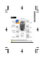
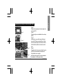
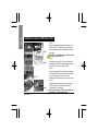
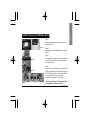
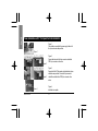
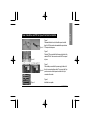
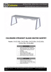
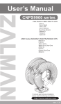
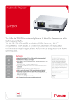
Installation Guide for
Intel Pentium 4 , AMD Athlon XP, Athlon 64
GH-PCU31-VH
DATE:0223
English
Table of Content
Checklist
Specification
Feature
3
4
4
Installation Instructions for Intel Pentium 4 Clips
Installation Instructions for AMD Athlon XP Clip
Installation Instructions for AMD Athlon 64 Clip
5
6
7
Power Installation and 3.5”Fan Speed Controller Installation
Power Installation and PCI Fan Speed Controller Installation
8
9
GH-PCU31-VH
-2-
English
Checklist
(1) GH-PCU31-VH Cooler
(2) GH-PCU31-VH
user's manual
(7) P4 Clips
(3) HeatSink Paste
(ShinEtsu X-23-7762)
(4) Speed Control&
3.5”front panel
(5) PCI rear panel
(8) K7 Clip
(6) Power cable
(9) K8 Clip
(10)Screw
Before use, please remove the bottom protective layer of the cooler.
Please make sure the computer is turned off and its power disconnected prior to installation.
-3GH-PCU31-VH
English
Specification
—
—
—
—
—
Heat Sink Dimension: 83 x 89 x 93mm
Rated Speed:2000~4500 rpm
Rated Voltage: 4~12V
Noise:19.2~42.0dBA
Bearing Type: 2 Ball Bearing
Feature
—
—
—
—
—
—
—
—
—
Unique patent for K8, K7 and P4 platform designs
Smart IC controller for noise and cooling
Top and bottom double airflow inlet central-blower
Attractive LED lights display
Multi-cooling of CPU and surrounding components
Heat pipe design
VR control function, suitable for both 3.5”front panel and PCI rear panel
Tool-free and easy clip install
Heat sink structure with entirely copper-based design
— Advanced heat sink paste included (ShinEtsu X-23-7762)
GH-PCU31-VH
-4-
Figure 1
Figure 2
Figure 3
Figure 4
Figure 1
Please add an adequate layer of heat sink paste on the
surface of the CPU.
Figure 2
Figure showing the correct installation of the cooler atop
the CPU.
Figure 3
Hook the clip on one end of the cooler with the insert
space at the CPU base (as seeing left Figure 3).Firmly
push downwards to clip the cooler end in place. Do the
same for the other clip of the cooler to secure cooler in
place.
Figure 4
Connect the yellow 3-pin connector cable of the cooler to
the CPU fan connector located on the motherboard.
Clips Installation is now complete.
Note: Please refer to page 8 & 9 for power installation
and installation of the fan speed controller.
-5GH-PCU31-VH
English
Installation Instructions for Intel Pentium 4 Clips
English
Installation Instructions for AMD Athlon XP Clip
Figure 1
Figure 2
Figure 3
Figure 4
GH-PCU31-VH
Figure 1
Please add an adequate layer of heat sink paste on the
surface of the CPU. The picture on the right shows the
three insert spaces on the cooler bracket where the CPU
clips attach.
Attention!! The indication arrow on the cooler must
align with the central CPU clip.
Figure 2
Place the cooler atop the CPU and insert the indication
arrow side of the cooler in the space between the central
jut of the CPU socket and the edge of the CPU.
Figure 3
Align the three spaces on the cooler with the three clips
on the base of the CPU and then push firmly downwards
to lock the cooler securely in place. A flat-head
screwdriver can also be used to secure the clips in place.
Figure 4
Connect the yellow 3-pin connector wire of the cooler to
the CPU fan connector located on the motherboard.
Clip Installation is now com plete.
Note: Please refer to page 8 & 9 for power installation
and installation of the fan speed controller.
-6-
Figure 1
Please add an adequate layer of heat sink paste on the
surface of the CPU.
Figure 1
Figure 2
Figure 3
Figure 2
Figure showing the correct installation of the cooler atop
the CPU.
Figure 3
Align the three insert spaces of the clip with the three juts
on the CPU socket and then push firmly downwards to
hold the clip in space.
Figure 4
Push the lever on the side of the cooler towards the lever
position on the base of the CPU to secure the cooler atop
the CPU. Connect the yellow 3-pin connector cable of the
cooler to the CPU fan connector located on the
motherboard. Clip Installation is now complete.
Note: Please refer to page 8 & 9 for power installation
and installation of the fan speed controller.
Figure 4
-7-
GH-PCU31-VH
English
Installation Instructions for AMD Athlon 64 Clip
English
Power Installation and 3.5” Fan Speed Controller Installation
Figure 1
Connect the power cable of the power supply to the end of
the 4-pin connector cable provided.
Figure 1
Figure 2
Figure 3
Figure 2
Connect the other end of the 4-pin connector cable to the
PCB 4-pin connector on the cooler.
Figure 3
Securely hold the 3.5”fan speed controller bracket in place
with the screws provided. Connect the 3-pin connector
cable of the controller to the PCB 3-pin connector on the
cooler.
Figure 4
Figure 4
GH-PCU31-VH
Installation is complete.
-8-
Figure 1
Disassemble the turn knob, bolt and fan speed controller
from the 3.5”front panel and reassemble these parts onto a
Figure 1 PCI rear panel in sequence.
Figure 2
Figure 2
Place the PCI rear panel with the fan speed controller in the
selected PCI slot. Use screws to secure the PCI rear panel
in place.
Figure 3
Connect the power cable of the power supply to the end of
the 4-pin connector cable provided. Then connect the 3-pin
Figure 3 power connector on the fan speed controller to the 3-pin
connector on the cooler.
Figure 4
Figure 4
Installation is complete.
-9-
GH-PCU31-VH
English
Power Installation and PCI Fan Speed Controller Installation