1
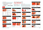
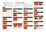
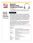
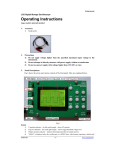
Two-channel Oscilloscope DSO 094
User Manual
For related documents please
visit www.jyetech.com
Rev. 02
Applicable Model: 09401
First Time Powering UP
Battery was disconnected for transportation reason. You need to
connect it before powering the device up. Please follow the steps
below to connect battery:
Panel & Connectors
Push: power ON
Hold: power OFF
Turn: adjustment
Channel conf ig.
Test Signal
1Vpp / 1KHz
1 ) Unscrew the two screws at back cover. Remove back cover.
2 ) Battery was attached to the inner side of back cover. Insert its
connector to the header on PCB (marked as "BATT" at the side of
USB connector) as shown in the photo at right.
3 ) Put back cover back and screw it up.
Tog gle RUN/HOLD
Ch 1 (Y) Sensitiviy & Position
Ch 1 (Y) Input
Time base & Horizontal position
Alternative functions
Ch 2 (X) Input
Trigger Lev el, Slope, Source, & Mode
Ch 2 Couple
Select
Ch 2 (X) Sensitiviy & Position
Trigger level in dicator
Test Signal
1Vpp / 1KHz
Ch 1
V. Pos
Ch 1 (Y) Input
No connection
USB Connector
Trig Point
Indicator
Dis playe d portion
of capture buffer
Power On - presssing [ADJ] knob
Power Off - holding down [ADJ] knob for about 2 - 3 seconds
2. Setting Parameters
Ch 1 sensitivity,
couple, & position
Ch 2 sensitivity,
couple, & position
Ch 2
V. Pos
Frequently operated parameters are grouped into four catagories and governed by four buttons
respectively, as listed in the table below. When a parameter is selected the corresponding
indicator is highlighted. Turning [ADJ] knob will change the parameter.
Catagory
Time ba se & H. Position
Ch 1
Vertical
Trigger level,
slope, & source
Ch 2
Vertical
Trigger mode
Horizontal
Trigger
Modes & Menu
Y/X Mode Screen
Y/T Mode
This is the most commonly used mode that
displays signal-to-time relationship.
Y Pos.
Sampling
Rate
Y channel as
trigge r source
This mode can be used to graph relationships
between two signals. In this mode Ch 1 becomes Y
and Ch 2 becomes X (see photo at right).
X Pos.
MENU
Parameters
Selecting Button
Adjustment
Sensitivity
Position
Couple
Sensitivity
Position
Couple
Ø Time base
Ø Position
[CH 1]
Turning
[ADJ]
[CH 2]
Turning
[ADJ]
[S/DIV]
Turning
[ADJ]
Ø
Ø
Ø
Ø
[TRIGGER]
Turning
[ADJ]
Ø
Ø
Ø
Ø
Ø
Ø
Level
Slope
Source
Mode
3. Special Functions
Functions
Button Action
Toggle HOLD/RUN state
Pressing [HOLD]
Freezing waveforms for static veiwing
Bring up Function Menu
Pressing [MENU]
Use menu to switch modes, save/recall waveforms, etc.
LCD backlight ON/OFF
Holding [ALT]
Fast adjustment ON/OFF
Pressing [ALT] at
specific cussor
locations
Persistent display ON/OFF
Pressing [ALT] when
cursor is at Timebase
Clear waveforms
Holding [S/DIV]
Clearing the whole waveform buffer as well as display
Ch 1 0V level alignment
Holding [CH 1]
Aligning 0V level of Ch 1 to its position indicator
Ch 2 0V level alignment
Holding [CH 2]
Aligning 0V level of Ch 2 to its position indicator
Menu is used to switch modes and perform special functions. Press [MENU] botton to enter menu
and press [HOLD] to execute selected item. Press [MENU] to exit.
Menu Function Summary
Functions
Select Y/T mode
Select Y/X mode
Save captured waveform to EEPROM
Recall saved waveforms
Send screen to PC as bitmap file
Change record length (waveform buffer size)
Change trig position (pre-trig buffer size)
Change trigger sensitivity
Restore settings to factory default
Reboot the oscilloscope (enter bootloader)
DN094-02v01/2012-05
Remarks
Couple is directly set by slide switch at
the left side of panel and not controlled
by [CH 1] button.
Couple is directly set by slide switch at
the left side of panel and not controlled
by [CH 1] button.
The table below lists some frequently used special functions and related button actions.
X Pos.
Y Pos.
Y/X Mode
Item
DSO Y/T
DSO Y/X
SAVE WAVEFORM
RECALL WAVEFORM
SEND SCREEN
CHANGE REC. LEN
CHANGE TRIG POS
CHANGE TRIG SEN
RESTORE DEFAULT
REBOOT
Connect battery
Menu
Ch 1 Couple
Select
Ch 2 (X) Input
Basic Operations
1. Powering ON/OFF the Device
IMPORTANT
Maximun allowed input voltages
are 50Vpk for 1X probe and 400Vpk
for 10X probe.
Explantions
When vertical position (Ch 1 & Ch 2), horizontal position,
or trigger level is highlighted(selected) pressing [ALT] will
turn on Fast Adjustment, which increases the adjustment
incremental to 5 (or 25 for H. position) from default value 1
4. About Rolling Display Mode
WARNING !
DO NOT ATTEMPT TO USE THE
DEVICE TO MEASURE LIVE
LINE VOLTAGE DIRECTLY!!!.
When Timebase is set to 0.1s/Div or slower DSO 094 enters Rolling Display Mode . In
this mode traces shift (rolling) from right to left across screen to display slow signals.
5. Calibration of 10X probe
Please refer to the technical note " How to Calibrate 10X Probe " (www.jyetech.com/
Support/HowToCalibrate10xProbe.pdf) for details.
Advanced Operations
Set up USB Connection
To use USB connection PC driver for CP2102 needs to be installed. The driver can be
downloaded at www.silabs.com/products/mcu/pages/usbtouartbridgevcpdrivers.aspx.
Windows driver is also available at www.jyetech.com/Support/Drivers&Tools.php .
Save Captured Waveform
Press [MENU], scroll to "SAVE WAVEFORM" and press [HOLD]. Follow screen
instructions to save waveform to selected buffer.
Recall Saved Waveform
Press [MENU], scroll to "RECALL WAVEFORM" and press [HOLD]. Follow
screen instructions to recall saved waveform from selected buffer. Recalled waveform is displayed under HOLD state.
Send Screen as Bitmap File
1 ) Connect USB cable. Run a PC application that can handle XModem Protocol
(Windows HyperTerminal, for example). Set communication format to 38400bps,
8 data bits, 1 stop bit, no parity, no flow control and prepare it for file receiving.
2 ) Adjust captured waveform so that the interested portion is displayed on screen.
3 ) Enter MENU and execute "SEND SCREEN".
You will see screen as shown in photo at right.
4 ) You can either start sending by first pressing
[HOLD] button then enabling PC receiving.
Or you can first enable PC receiving then press
[HOLD] to start sending. We recommend you
use the former sequence because it usually
results in shorter wait time.
Change Record Length (waveform buffer size)
Press [MENU], scroll to "RECALL WAVEFORM" and press [HOLD]. Follow
screen instructions to select record length desired.
Change Trigger Position (Pre-trig Length)
Trig position is where the trig point is over the whole waveform buffer (see figure
below). You may like to set trig position closer to buffer start or to buffer end
depending on which portion of waveforms you are more interested.
Pre-trig Length
Trig position
Buffer Size
In DSO 094 trig position is represented as percentage of buffer size. To change it
press [MENU], scroll to "CHANGE TRIG POS" and press [HOLD].
Change Trigger Sensitivity
Trig sensitivity is the minimum level difference required to produce trigs. In DSO
094 this is expressed as number of one-tenth of major screen division size.To change
it p ress [MENU], scroll to "CHANGE TRIG SEN" and press [HOLD]. The adjustable
range is 2 - 40 (0.2 - 4 division). Default value is 4.
Restore Factory Default Settings
Press [MENU], scroll to "RESTORE DEFAULT" and press [HOLD]. Default values
are listed in the table at next page.
Channel Configuration
DSO 094 can be set to display two channels or one channel only by the Channel
Configuration Switch at top-left corner of panel. When it is set to one channel only
the not-selected channel is not displayed. However, its signal is still captured.
Built-in Test Signal
The built-in test signal is a square wave signal with fixed frequency of 1KHz and
amplitude of about 1V peak-to-peak..
Maintenance
Battery Running Time
DSO 094 uses one 3.7V 1200mAh Li-ion battery. When fully charged it can last
about 4 hours. If LCD backlight is turned off it can last longer.
The Built-in Battery Charger
The built-in charger is programmed to charge battery at current about 100mA. It
requires about 16 hours to fully charge a completely discharged battery. To charge
battery connect the USB port to PC or power adapter with USB connector. The
battery sign at top will blink indicating charging is under going.
Powered From USB
When connectting the device to USB good quality cable is strongly recommended.
Bad cable could create too much voltage drop and consequently the device may
not be able to work properly.
Firmware Upgrade
From time to time firmware may need to be upgraded for new functions or
improved performance. This can be done by the built-in bootloader. For how the
bootloader works and how to use it please refer to www.jyetech.com/Products/
LedScope/e094.php
Hint: The reboot function under Menu is a quick way to enter the bootloader.
Specifications
Number of Channel
Max. Sampling Rate
Analog Bandwidth
Max. Sensitivity
Max. Input Voltage
Input Impedance
Resolution
Max. Record Length
Fastest Time Base
Trigger Modes
Trigger Position
Num. of Waveform Mem.
Screen Size
Power Supply
Current Consumption
Dimension
Weight
Parameter Ranges and Defaults
2
50MSa/s
0 -- 10MHz
10mV/div
50Vpk (1X probe), 400Vpk(10X probe)
1M ohm/20pF
8 bits
8000 points
0.2us/div
Auto, Normal, Single
0% -- 100%
4 (up to full record lenght)
128 X 64
Battery/USB
~300mA (with LCD backlight on)
140 x 70 x 30mm
190g
Technical Support:
Parameter
Time base
H. Position
Ch 1 Sen.
Ch 1 Couple
Ch 1 V. Pos.
Ch 2 Sen.
Ch 2 Couple
Ch 2 V. Pos.
Trigger Mode
Trigger Slope
Trigger Level
Trigger Src.
Trigger Pos.
Trigger Sen.
Record Length
Working Mode
Range
10M/div -- 0.2us/div
0 -- (Rec. Len. - 100)
2V/div -- 10mV/div
DC, AC, GND
-127 -- +127
2V/div -- 10mV/div
DC, AC, GND
-127 -- +127
Auto, Normal, Single
Falling, Rising
-127 -- +127
Ch 1, Ch 2
0% -- 100%
2 -- 40
500 -- 8000 points
Y/T, Y/X
Forum: http://forum.jyetech.com
Email: [email protected]
Default
1ms/div
0
10mV/div
10
10mV/div
-10
Auto
Falling
0
Ch 1
50%
4
1000
Y/T