1
SPRING
User’s Manual
Nicolas Dubois
Xavier Guidetti
Timothy Marvel
Nicolò Sitzia
Supervisor : Dr. Matteo Galli
This manual is written as an introduction and a guideline for mechanical engineering students on how to
use the SPRING project room, the tools which are available in it and as a starting point for DIY jobs.
We wish to thank Dr Matteo Galli who has supervised the reorganising and has always been helpful for
solving problems we encountered.
2
SPRING - User’s Manual
Table des matières
1 Introduction
4
2 General rules
4
3 Drilling
3.1 Drill Press . . . . . . . . . . . . . . . . . . . . . . . . . . . . . . . . . . . . . . . . . . . . .
3.2 Handheld drill . . . . . . . . . . . . . . . . . . . . . . . . . . . . . . . . . . . . . . . . . . .
5
7
8
4 Cutting
9
4.1 Hand saws . . . . . . . . . . . . . . . . . . . . . . . . . . . . . . . . . . . . . . . . . . . . . 9
4.2 Electric coping saw . . . . . . . . . . . . . . . . . . . . . . . . . . . . . . . . . . . . . . . . 10
4.3 Jigsaw . . . . . . . . . . . . . . . . . . . . . . . . . . . . . . . . . . . . . . . . . . . . . . . 11
5 Polishing
13
5.1 Sandpaper . . . . . . . . . . . . . . . . . . . . . . . . . . . . . . . . . . . . . . . . . . . . . 13
5.2 Belt sander . . . . . . . . . . . . . . . . . . . . . . . . . . . . . . . . . . . . . . . . . . . . 13
6 Gluing
14
6.1 Glue Gun . . . . . . . . . . . . . . . . . . . . . . . . . . . . . . . . . . . . . . . . . . . . . 14
6.2 Epoxy glue . . . . . . . . . . . . . . . . . . . . . . . . . . . . . . . . . . . . . . . . . . . . 15
7 Hot air gun
16
8 Threading, tapping and filing.
17
8.1 Threading a rod . . . . . . . . . . . . . . . . . . . . . . . . . . . . . . . . . . . . . . . . . 17
8.2 Threading inside a hole . . . . . . . . . . . . . . . . . . . . . . . . . . . . . . . . . . . . . 18
8.3 Counterboring . . . . . . . . . . . . . . . . . . . . . . . . . . . . . . . . . . . . . . . . . . 18
9 Welding/Soldering
19
9.1 Soldering iron . . . . . . . . . . . . . . . . . . . . . . . . . . . . . . . . . . . . . . . . . . . 19
10 CNC
10.1 The machine . . . . . . . . . . . . . . . . . . . . . . . .
10.2 Tutoriel d’usinage 2.5D . . . . . . . . . . . . . . . . . .
10.2.1 Drawing . . . . . . . . . . . . . . . . . . . . . . .
10.2.2 Drawing in CamBam . . . . . . . . . . . . . . .
10.2.3 Machining settings in CamBam . . . . . . . . . .
10.2.4 Fixing the Sheet . . . . . . . . . . . . . . . . . .
10.2.5 Machining with Mach3 . . . . . . . . . . . . . . .
10.3 3D machining . . . . . . . . . . . . . . . . . . . . . . . .
10.3.1 Drawing . . . . . . . . . . . . . . . . . . . . . . .
10.3.2 Drawing using CamBam . . . . . . . . . . . . . .
10.3.3 Creating the machining passes with CamBam . .
10.3.4 Fixing the motherpiece . . . . . . . . . . . . . .
10.3.5 Machining with Mach3 . . . . . . . . . . . . . . .
10.3.6 Fastening the mother piece for second part of the
10.3.7 Modifying the G-Code in CamBam . . . . . . . .
10.3.8 Second machining pass with Mach3 . . . . . . . .
10.4 Machining tables . . . . . . . . . . . . . . . . . . . . . .
. . . . . . .
. . . . . . .
. . . . . . .
. . . . . . .
. . . . . . .
. . . . . . .
. . . . . . .
. . . . . . .
. . . . . . .
. . . . . . .
. . . . . . .
. . . . . . .
. . . . . . .
machining
. . . . . . .
. . . . . . .
. . . . . . .
.
.
.
.
.
.
.
.
.
.
.
.
.
.
.
.
.
.
.
.
.
.
.
.
.
.
.
.
.
.
.
.
.
.
.
.
.
.
.
.
.
.
.
.
.
.
.
.
.
.
.
.
.
.
.
.
.
.
.
.
.
.
.
.
.
.
.
.
.
.
.
.
.
.
.
.
.
.
.
.
.
.
.
.
.
.
.
.
.
.
.
.
.
.
.
.
.
.
.
.
.
.
.
.
.
.
.
.
.
.
.
.
.
.
.
.
.
.
.
.
.
.
.
.
.
.
.
.
.
.
.
.
.
.
.
.
.
.
.
.
.
.
.
.
.
.
.
.
.
.
.
.
.
.
.
.
.
.
.
.
.
.
.
.
.
.
.
.
.
.
.
.
.
.
.
.
.
.
.
.
.
.
.
.
.
.
.
.
.
.
.
.
.
.
.
.
.
.
.
.
.
.
.
.
20
20
20
20
21
29
34
35
39
39
39
45
48
49
53
54
54
56
TABLE DES MATIÈRES
3
11 Online resources
11.1 Classical machining . . . . . . . . . . . . . . . . . . . . . . . . . . . . . . . . . . . . . . . .
11.2 CNC . . . . . . . . . . . . . . . . . . . . . . . . . . . . . . . . . . . . . . . . . . . . . . . .
11.3 CamBam Documentation . . . . . . . . . . . . . . . . . . . . . . . . . . . . . . . . . . . .
57
57
57
57
12 Inventory
59
4
1
SPRING - User’s Manual
Introduction
The name SPRING is a concatenation of the following french words : (Salle de PRojet pour INGénieur ).
The SPRING workshop was created as part of a bachelor project during the 2015 spring semester. The
aim of the project was to refurbish the room in a economical and safe way so it could be used as a
workshop by the students.
Access to the workshop is done through the «CAMIPRO» system. Only people with the explicit authorisation from the Mechanical Engineering department are allowed to work in it.
A large set of manual and power tools, allowing the students to complete many tasks, are available in
the workshop. In the first part of this presentation we will take a closer look at the general rules and
safety requirements. Later, we will explain how to use the tools present. At last, we will offer detailed
explications on the functioning of the CNC machine.
2
General rules
The following rules must be followed at all time in the workshop to prevent any form of accidents of
happening.
Safety goggles are available in the blue drawer box next to the CNC machine. Their purpose is to protect
eyes against any form of injury, for instance when drilling a hole in a block of aluminium with the drill
press !
Figure 1 – UVEX safety goggles
Goggles must be worn when operating any machine with the blue «safety glasses» sticker. We recommend
keeping goggles on as long as power tools are being used.
A safe distance must be kept from any power tool. Long hair must be tied up and any of the following must
not be worn : jewelry, scarfs, ties, wristbands or indeed any piece of clothing which could get tangled up in
the tool. Also, anyone operating am power tool is responsible of operating it and must stay in the room
while it is operating. The use of any tool under influence of drugs, alcohol, medicine or any other behaviour
altering substance is strictly prohibited. Smoking and eating are not allowed in the room. The rules are
available on the door, in case of any doubt please read them carefully.
3
DRILLING
5
Figure 2 – Safety goggles sticker
3
Drilling
Choice of the drill bit A specific tool exists for each type of material, this general rule is especially
true for drilling. In the workshop metal and wood bits are available.
The wooden tips are identifiable by their central sharp point and two side-going blades. The metal tips
simply have two sharpened sides.
In order to drill other materials than wood or metal, one needs a specific drill bit. Hard mineral material,
concrete and bricks for instance, require a specific concrete drill bit and percussion drill (not available
in the workshop).
(a)
(b)
(c)
Figure 3 – wood bit(a), metal bit (b) concrete (c)
Drilling into plastic material can be done with the metal drill tips. This operation however requires
cleaning if the tips since the plastic will melt onto the tip. The diameter of a drill tip is usually indicated
on the box, in case of doubt use a calliper to determine the tips dimensions.
Choosing the rotational speed A proper operating speed, avoiding any structural damage to the
piece, is a fundamental parameter to set for any drilling operation.
6
SPRING - User’s Manual
There are many tables indicating the operating speed (mm/min) according to the size of the tool and
the material to be drilled into.
We have prepared the following table for your convenience, however keep in mind that the wider the drill
bit gets, the slower the operating speed must be. The main danger is a too big operating speed.
Recommended operating speed (in RPM)
according to the material of the piece being drilled into and tool diameter
Soft wood Hard wood Plastic/PVC/PET Aluminium and Dibond
3mm (1/8")
1800
1200
1500
1500
6mm (1/4")
1800
1000
1500
1500
9mm (3/8")
1800
750
1500
1000
12mm (1/2")
1800
750
1000
750
15mm (3/5")
1800
500
750
500
The speed at which you descend into the material, the feed rate, should be around 2-3 mm/s. If you
hear any suspicious noise, odds are something went wrong, try again using a lower feed rate or operating
speed.
If you can not change the gear in which the drill press is set, try using the hand held drill.
Once the speed has been determined in m/min one needs to convert it into RPM’s using the following
formula : n = 1000v
πd
where v is the cutting speed and d the diameter of the drill tip. If the calculated speed using the above
formula is not achievable, use the next inferior available speed. On-line information can also be useful,
especially for exotic materials.
Figure 4 – Gearbox for the drill press
Choosing the drill As long as using the drill press is possible, it is recommended to use it. It’s more
accurate and more powerful than the hand held drill. The hand held drill is useful for operations on large
objects which can not be moved easily. It can also be used as an electric screwdriver with special shaped
bits.
Safety rules for drilling Glasses are mandatory for any drilling operation. The risk of a piece of
matter being projected into the user’s eyes is real. In order to prevent anyone from being spun around
by the drill, long hair must be tied and any of the following must not be worn : jewelry, scarfs, ties,
wristbands, large/long sleeves. Hands must be kept out of the drilling area. Once finished, the removal
3
DRILLING
7
of any chips should be done with a brush to avoid getting fingers burned. The chips and drill bit can
reach high temperatures and must cool first. Cleaning the used parts is compulsory.
3.1
Drill Press
Safety rules Besides the general safety rules, special safety rules apply to anyone using the drill press.
The piece of matter being drilled into must always be safely held by the vise. Under no circumstances
should small pieces be held by the operators hands, the risk of injury is very high. The «ALDURO» vise
is available next to the drill press.
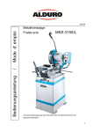
Figure 5 – ALDURO BM-11 Drill press
Operating instructions To modify the operating speed on the drill press, one has to access the gearbox on top of the drill press. In the gearbox the position of the belt can be changed, the higher the faster.
Please note that the belt should always operate horizontally. To change the position, unscrew the screw
on the left hand side of the drill allowing the back camshaft to move towards the front haft to ease the
tension in the belt. Move the belt in the desired position using the specific j shaped tool available in the
gearbox. Once in place, use the crowbar to force the back shaft back into position and lock the screw.
Once the speed is set, the drill bit must be placed into the jaw chuck. To access the jaw chuck, the
protection Plexiglas must be turned sideways. It is important that the drill bit is centred in the jaw
chuck. Take the piece to be drilled into and place it into the vise. The height of the support piece on
which the vise is sitting must be adjusted so that the piece only sits slightly lower than the drill bit at it’s
rest point. When everything is in place, the drill can be turned on using the green button. Please note
that the Plexiglas window needs to be in the closed position for the drill to start. To start drilling, slowly
lower the drill bit using the big shaft on the right hand side of the drill. The speed of descent should be
proportional to the material removal rate of the drill bit. The depth of the hole can be measured using
the depth indicator on the drill press. Once the desired depth has been reached, gently let the drill bit
rise to it’s rest location. Use the red button next to the green start button to turn the drill off. Once
the drill has stopped completely, rotate the Plexiglas window into the open position, clean the the chips
with a brush or a vacuum cleaner and finally release the drilled piece out of the vise. Finally, clean and
put away all the used equipment.
8
SPRING - User’s Manual
In case of an emergency or malfunction the drill can be stopped using the round red emergency button.
Also, it is possible that the jaw chuck loosens itself from the drill press, this is because the jaw chuck has
been mounted in such a way to prevent it from jamming if the cutting toque is to big. In case of such
a disturbance, put the jaw chuck back into place, once the drill bit has been removed, using a rubber
mallet.
Tips When drilling an end to end hole into wood, we advise that you use an extra wooden piece as a
buffer, this will make for a better surface. If the piece is very fragile, use two buffers, one on top, one
underneath.
3.2
Handheld drill
Safety rules On top of the standard safety rules, specific rules apply to the hand held drill. The pieces
to be drilled into must be fixed to an immobile piece of furniture, using either a vise or crew clamp. Only
turn the drill on once it is pointing in the direction of the piece and always store it in such a way that it
can not be hit accidentally. Also note that inhaling of chips and dust when drilling into hard materials
should be avoided.
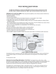
Figure 6 – BOSCH GSR 14, 4-2 LI hand held drill
Operating instructions After having checked that the battery is loaded and in place, lock the jaw
chuck manually. Choose the desired type of work to be done on the numbered band, drilling in our case,
shown by a drill bit. Two operating speeds are achievable, (1 slow, 2 fast), choose the appropriate one.
It is essential, to avoid accidents and to drill a straight hole, to be in a stable position whilst drilling.
Apply a fair amount of pressure on the drill and start drilling. If a lot of dust and chips are being created
by the drilling, have someone else hold a vacuum cleaner during the drilling. Once the hole has been
finished and as soon as the drill tip has cooled off, clean the drill and tidy up the workspace.
The hand drill can also serve as an electric screwdriver with the proper tips. The locking torque applied
on the screw can be chosen between 1(smallest) and 14 (biggest).
Tips If drilling a large diameter hole, first drill a small hole at the centre of the desired hole which will
the serve as a centre reference for a large drill tip.
4
CUTTING
4
4.1
9
Cutting
Hand saws
Safety rules On top of the normal safety rules, it is important to pay attention to the hand holding
the piece in place so that any injuries may be avoided. Never leave your fingers in the cutting area.
Figure 7 – ULMIA 352 angle saw
Choice of the saw The blade must be suited for the material being cut into. Blades for both wood
and metal are available. The main difference between the two different blades is the size of the teeth.
Also, in the case of the ulmia saws, the blades have different colors and the type is indicated on the saw
«metal» and «bois» for wood.
(a)
(b)
Figure 8 – Metal blade (a) Wooden blade (b)
Operating instructions To make sure the piece is not moving whilst it’s being cut it is best to clamp
it on the saw using a G-clamp. They are available in the blue draw chest next to the drill press.
The angle at wich the cut is made has to be set. The available angles are ±45, ±36◦ , ±30◦ , ±22.5◦ .
Once set the user can start to cut into the matter. The cutting process involves two different steps. The
active step during which pressure is applied in a forward motion and a passive phase where the blade is
brought back to it’s initial position. It is best to use the whole length of the blade. The recommended
cycle rate is 1 Hz.
Fingers must be kept out of the cutting zone at all times.
10
SPRING - User’s Manual
Figure 9 – G-clamp and simple clamp
Once the cut has been finished, clean the blade and the surrounding area with a vacuum cleaner.
When cutting metal, don’t forget that the edges might be sharp, if this is the case, use a metal file to
round the edges to avoid cuts. When cutting wood, watch out for splinters !
Tips If a very precise cut is needed in wood or polymer plastic, it is possible to use the metal blade
since it’s finner yet still capable to cut through softer than metal matter. In any other situation we
recommend the use of the wooden blade since it requires less effort and time. NEVER use the wood
blade for any metal object.
4.2
Electric coping saw
Safety rules On top of the general safety rules mentioned above, other specific rules apply to this
power tool. We highly recommend the use of gloves, especially if the pieces cut are small. Never let the
saw out of sight without making sure it has been properly turned off.
Changing the blade To change a blade proceed the according to the following instructions. Loosen
the stress in the blade using the white leaver. Unscrew the top and bottom attachment. Gently take the
blade out of position and insert the new blade into position. Tighten the top and bottom attachments
using the adjustment wheel to make sure the stress in the blade is sufficient once the white leaver is back
into position.
Operating speed and choice of the blade
Material
Operating speed [%]
Type of blade
Wood/MDF
>50
Wood
Plastic/PVC
>50
Metal
PET
>50
Metal
Aluminium
>50
Metal
Dibond
>50
Metal
The speed is expressed as a percentage of the maximal operating speed. Please make sure that the right
type of blade is mounted. A wood blade won’t last long cutting aluminium.
4
CUTTING
11
Figure 10 – EXCALIBUR EX-16 CEBS electric coping saw
Operating instructions To start off with the blade must be chosen according to the material of
the piece. Blades for aluminium and wood are available. Once the proper blade has been chosen, make
sure nothing can get into the way of the piece being cut. Keep in mind that a large piece being turned
into different directions might take up more space than expected. Plug the operating tip of the vacuum
cleaner into the chip exiting route on the lower right hand side of the saw. It is highly recommended to
work with the vacuum cleaner, it can avoid the user a long and hairy cleaning of the saw. Set the height
of the safety system to be slightly higher than the piece beingg cut, this prevents the piece of hanging
on to the blade. Glasses must be worn during the operation of this power tool. Before turning on the
saw, make sure the vacuum cleaner is in place and working and check to be sure that the speed is set to
the minimum. This greatly reduces the risk of injury in case the blade has not been mounted properly.
Set the operating speed to the speed best suited for the material and start cutting. Never make any
sudden moves, this might break the blade and the cut will be of a mediocre quality. Advance slowly and
firmly along the cutting lines. When the blade exits the piece, slow down to avoid any sudden gestures.
When the cutting is done, turn the speed back to the minimal setting before turning the machine off.
Don’t forget to clean the area !
4.3
Jigsaw
Safety rules On top of the overall rules applying to the workshop, special rules apply to the jigsaw.
Make sure the piece being cut into is well anchored to the table to prevent int from moving during the
cutting operation. We strongly recommend the use of gloves and ear protection.
12
SPRING - User’s Manual
It is important to remember that a jigsaw is a tool with a free blade, it is important not to cut into
either the power cable nor any part of one’s body.
Choice of the blade The choice of the blade should be done according to the following table :
Material
Blade Type
Maximal depth [mm]
Feedrate [mm/s]
Wood
Wood
140
10
Steel
Metal
10
2
Aluminium
Metal
20
3
For the blade speed, it is necessary to remember that it depends inversely on the material hardness. For
a soft wood, it can be set at the maximum speed, while for aluminium it has to be very slow.
Changing the blade The blade needs to be changed when it is damaged or when cutting into a
different material. Loosen the mount and take the blade out. Pay attention because it will get out alone
as the spring behind it will push it outside. Loosen again the mount and insert the new blade so that it
is well placed at the bottom. Verify if the blade is safely positioned.
Operating instructions To start off with, draw a line along which the cut is supposed to go. Use
a pencil for wood or a permanent marker for metal. This line is important since, provided it has been
properly followed, it guarantees a good cut. Place the piece in such a way that it can be clamped into
position using g-clamps.
Make sure the electric cable is long enough and that the proper blade is on the saw.
Start cutting by pushing the saw into the piece. Don’t push too hard, this will affect the quality of the
cut surface in a negative way. When arriving to the end of the piece, make sure the piece cut out will
not fall on the floor or cause any damage once it is loose from the original piece. Once finished, clean the
surrounding area and the saw itself.
Tips If two people are present, it can be a good idea that one of them vacuums the chips away as they
are being produced rather than waiting to clean the up at the end. For long or bulky pieces, we highly
recommend that two people do the job. Whilst one makes sure the pieces don’t move, the other one can
do the cutting without worrying. Also make sure that the piece cut out will not break or cause damage
due to it’s own weight.
5
POLISHING
5
5.1
13
Polishing
Sandpaper
Safety rules Sand paper is a harmless tool. Goggles are not compulsory but can be useful if the piece
sanded is above the user’s eyes. Also, the user pay attention not to hold onto the paper by the rugged
side.
Operating instructions After having cut a piece, it frequently happens that the cut is not completely
clean. This is when sandpaper should be used. Start by fixing the piece in a vice and then start off sanding
the piece with a low number (rough) piece of sandpaper. Once all the large irregularities have gone, use
smaller and smaller grain (bigger numbers) and continue sanding until the surface has the desired finish.
Tips Use large grain (small numbers typically 80) to start off with and then go down the size of grain.
Don’t start off with a small grain (large number), it is a waste of time and sandpaper.
5.2
Belt sander
Safety rules On top of the above mentioned safety rules, other tool specific rules must be followed.
During the operation, a large amount of dust will be generated, we recommend to avoid inhaling it. Also,
it is important that fingers are kept out of the belt area to prevent injuries. Glasses are compulsory. Use
the
Operating instructions Start off by fixing the piece in a vice or by clamping it onto a table. We
recommend wearing an apron to prevent the dust of going onto your clothing. Plug the bystander in and
start work. Once the job is finished, unplug the belt sander and thoroughly clean the piece using the
vacuum cleaner.
Tips A second person vacuuming the dust away as it is being produced is a good idea, it creates much
less of a mess in the workshop.
14
6
6.1
SPRING - User’s Manual
Gluing
Glue Gun
Hot glue is a very efficient and wide spread way of gluing all sorts of different materials. It is an alternative
to welding and screwing worth considering for medium size parts which are not designed to undergo large
amounts of stress.
Safety rules Hot glue implies hot temperature. The temperature of the glue gun can vary between
110˚C and 190 ˚C. Touching it can burn your skin and have long lasting effects on it. Newly deposited
glue will also be hot, so avoid touching it. In case of contact between hot glue and skin we recommend
not to puncture any resulting blisters.
We strongly advise against inhaling the fumes.
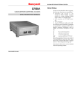
Figure 11 – RAPID EG 330 Glue gun
Operating instructions Prepare the surfaces to be glued together on a table and clean them. Take
the glue gun and insert a glue stick in the rear end of the glue gun if none is already present. Install the
small metal support piece allowing the glue gun to sit upright on it’s own when not in the user’s hand.
Plug the glue gun in the power socket and wait or it to warm up. During the time it takes to warm up,
leave a small container under the tip of the glue gun to avoid any excess glue of soiling the table. A
pickle glass jar screw cap is available for this purpose. Once the glue is at melting temperature, point
the tip at the surface to be glued and start by slightly pressing on the trigger to release the liquid glue.
Be careful with the quantities, too much glue might be visible after the operation and might be unstable
on the long run.
Once enough glue is on one piece, a large amount of pressure has to be applied on the two pieces whilst
the glue dries. After all the gluing has been done, wait for the glue gun to cool off before cleaning it off
6
GLUING
15
and putting it back into it’s box.
Tips Use g-clamps to press pieces together. No need to put a lot of glue on the desired surface, it might
end up overrunning.
6.2
Epoxy glue
Epoxy glue is a mix of resin and hardening compound. Once mixed, it becomes very resistant and allows
for extremely solid gluing.
Operating instructions Prepare paper towels, a piece of cardboard, toothpicks, a glue syringe and
of course the pieces to be glued together.
Break the white cap on the glue syringe off and squeeze out the desired amount of both liquids on
the cardboard piece. Clean the tip of the syringe with a paper towel. Once the resin and the hardening
compound have been well mixed using the toothpick, apply a thin layer of glue on the pieces to be joined.
Wait 10 hours for the glue to dry and reach it’s full material capabilities.
Figure 12 – Epoxy glue (left) and normal glue (right)
16
7
SPRING - User’s Manual
Hot air gun
Safety rules On top of the already mentioned safety rules for the room, specific safety rules apply to
the hot air gun. The maximal temperature the air gun can reach is 600 ˚C, thus it is very important
that it is never pointed at someone. We strongly advise the use of gloves to hold the part worked on in
place unless for the use of heat shrinking tubes for obvious problems concerning precision. Never lay the
hot air gun on it’s side. Always make sure the hot tip is pointing upwards. Watch out for inflammable
material !
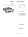
Figure 13 – Hot air gun
Operating instructions To start off with, prepare all the necessary material (the gun, the part,
cables, heat-shrinking tubes). Choose the tip best suited for your needs (heating a small point, around
a cable) and mount it on the gun. Plug the gun into a power socket and turn it on. The gun will need
approximately 10 seconds to warm up. Once the operating temperature is reached, start working !
Once the job is done, unplug and rest the gun with the tip pointing upwards to make sure the work
surface is not damaged.
It will take roughly 20 minutes for it to cool off. As long as touching it with your hands is not possible,
wait. Use the extra time to tidy up all the remaining tools used.
Tips For heat-shrinking tubes we suggest the use of power setting n˚7 and air flow setting n˚2.
Be careful not to damage any wooden pieces.
The hot air gun can be used to melt glue from the glue gun and PET to use as a basic "welding" material.
8
THREADING, TAPPING AND FILING.
8
17
Threading, tapping and filing.
Threading a rod is the mechanical operation of creating a screw thread. Industrial threading is done in
many different ways. Tapping a hole is the opposite operation : cutting an inner thread so that a screw
can hold in place. In the workshop, a series of taps, dies and drill bits are available in the following
dimensions. M3, M4, M5, M6, M8, M10 and M12.
The tables come from "Le B.A.-BA à l’atlier" de Jean-Marc Colomb, collaborateur technique de l’atelier
de l’Institut des matériaux de l’EPFL.
Safety rules Manually thread cutting involves no major safety risk as long as fingers are kept out of
the immediate cutting area, it is however a delicate process requiring a lot of manual skills.
Figure 14 – Threading dies
8.1
Threading a rod
Choice of the die The die must be chosen according to the rod that is to be threaded. The number
following Mx indicates the diameter in [mm]. A 6mm wide rod must be threaded with a M6 die.
Operating instructions To cut a thread on a rod, start by fastening the rod in a vise. If the rod
doesn’t have a chamfer, use a metal file to create one. After having measured the diameter of the rod
with a calliper, pick the right sized die.
Mount the die on the die wrench (big metal piece with a circle in the centre) and screw the screws on
each side without applying too much pressure on them. Oil or threading lube available in the Zinkol
orange/white container, must be applied on the rod.
18
SPRING - User’s Manual
Place the die vertically at the top of the rod, make sure it is placed exactly. Even a slight angle might
create a thread that isn’t aligned with the rod. Start by turning the die very slowly in the clockwise
direction. Keep in mind that the rod and the die must be co-centric for this operation to succeed. For
every full 360˚turn done cutting, make a counter clockwise 180˚rotation, this allows chips to be evacuated.
Once the target depth has been reached gently remove the die by turning it in the anti-clockwise direction
all the way to the top.
The job is finished, make sure the thread is co-centric with the rod. Don’t forget the cleaning !
8.2
Threading inside a hole
Diameter of the hole To thread a hole, the hole must be drilled before. The diameter of the hole
depends of the thread of the screw for which the hole is being made. The following table gives the size
of the drill tips available in the workshop according to the screw size and the size of the thread.
Diameter
Thread
Diameter of the hole D-thread
M2
0.40
1.60
M3
0.50
2.50
M4
0.70
3.30
M5
0.80
4.20
M6
1.00
5.00
M8
1.25
6.80
M10
1.50
8.50
M12
1.75
10.20
Operating instructions Start by choosing the tap which has the right diameter and insert it in the
tap wrench (easily identifiable by it’s v shaped vise). Place the tap vertically above the hole and start
turning into the hole once it has been lubricated. Make sure the the tap and the hole are co-centric
otherwise the thread will be cut sideways. Just like for external threading, for every full revolution of
the tool, make a half revolution going the other way to break of the chips. Once finished, clean out the
hole and the surrounding area and don’t forget to clean up the used area.
8.3
Counterboring
To drill a counterbore, a right sized hole must be drilled into the desired piece using the drill pres. For
a cylindrical shaped head the dimensions of the hole are givin in the table bellow.
Diameter
d2
d3
t1
d5
M2
2.20
3.30
1.60
4.60
M3
3.20
6.00
3.50
6.50
M4
4.30
8.00
4.50
8.60
The following definitions are used in the table :
d2 : diameter required for the frill
d3 : diameter of the screw head
t1 : depth of the counter-bore
d5 : diameter of the counter-bore
M5
5.30
10.00
5.70
10.40
M6
6.40
11.00
6.80
12.40
M8
8.40
15.00
9.00
16.40
M10
10.50
18.00
11.00
20.40
M12
13.00
20.00
13.00
23.90
9
WELDING/SOLDERING
9
9.1
19
Welding/Soldering
Soldering iron
Safety rules On top of the general rules for the room, specific rules apply for the soldering iron. The
user must make sure never to let the iron out of his eyesight when it is on. We don’t recommend the use
of gloves when soldering small parts because the user will not be as precise, thus we recommend being
particularly careful when it is being used. Goggles are mandatory. We also recommend users to avoid
inhaling the fumes from the soldering tin since it contains lead.
Figure 15 – ERSA ANALOG 60 soldering iron
Choice of the temperature When soldering pieces using soldering tin containing lead, a 300 ˚C
operating temperature is enough to melt the soldering tin.
Higher temperature will increase the toxic fumes and cause the welding tin to become very liquid and
maybe even to melt the surrounding pieces. A too low temperature will not create a solid weld and it
will be difficult to weld with it since it would require the user not to move during 30 seconds or more,
that can be difficult when every mm counts. This is especially true with electronic circuit boards.
Operating instructions To begin with, prepare all the necessary tools on the workbench. You will
need the following equipment : the soldering iron, soldering tin and the parts which are going to be
welded. The little sponge on the welding iron’s main frame must be humidified before use. This allows
the user to clean the tip of the soldering iron. Before plugging in the power socket, make sure all the
switches are in the off position and that the soldering tip is in it’s casing. Once the iron is plugged in and
the temperature has been selected, wait for the iron to reach it’s operating temperature without leaving
it by it self. another person seeing it might not guess that the iron is at 200 ˚C ! The indicator light will
start blinking when the temperature has been reached, the iron is fully operational.
Hold the soldering iron on the junction between the two parts to bee welded until little drops of soldering
tin start falling into the position. The amount of tin to be used depends on the size of the connection
to be made. The deposited tin can be reheated and worked into position until the desired weld has been
achieved.
Once the welding is finished, clean the tip of the welding iron on the little damp sponge when it is still
hot. Turn the iron off and unplug it. Before putting it away in it’s box, the iron must have cooled off to
room temperature (this can take 20 min). Never cool the iron of by using cold water ! Congratulations
you’ve finished welding !
20
10
SPRING - User’s Manual
CNC
Figure 16 – CNC
10.1
The machine
The CNC machine is a very useful and powerful tool. It’s accurate and efficient. The main parts of the
machine are : the main frame, the cutting area and the spindle. The machine has 3 degrees of freedom.
Two different types of machining are possible 2.5D and 3D. The difference will be explained in detail
using examples.
10.2
Tutoriel d’usinage 2.5D
The aim of this tutorial is to show the user how to completely achieve a 2.5D manufacturing process in
the workshop.
You will create a 2D document which will be translated using CamBam into G-code. Mach3 will then
interpret the G-code and transmit the information to the CNC machine.
The piece used for this example is a box designed for a pack of playing cards, but you are free to create
any piece of your own provided it is within the dimensions of the machine. The sheet used will be a 3mm
thick PET sheet. The surface is needed is roughly 30 cm by 30 cm.
10.2.1
Drawing
To begin with, a new project always starts with a new drawing. In the case of 2.5D machining, the drawing
must be a 2D drawing saved as a 2D file. The 3D drawing of the part is of no direct use. If a 3D drawing
is the only one available, make a 2D projection of the desired side. The 2D file must be saved as a .dxf
file format, which can be read by any of the following programs (Catia, SolidWorks, Adobe Illustrator,
Inkscape). If the drawing program allows for it, work in millimetres since it’s the unit used by the CNC.
This will also allow you to know the size of the part and will save time since no resizing process will need
to be done.
Keep in mind that the zero point will be set, drawing the piece close to the zero point will save time
during the placement of the sheet.
.dxf files can be created with CATDrawings of a Catia piece. Create a drawing in the XY plane on the
desired part and then save it as a .dxf file.
10
CNC
21
Figure 17 – Saving .dxf file in Catia
The .dfx files used for this tutorial are in "to be filled"
The .CatPart files are also available if anyone is interested by modifying the design for himself. Once the
file is ready put it on a usb stick and transfer it to the computer controlling the CNC. Please note that
this computer is NOT connected to the Internet.
10.2.2
Drawing in CamBam
Open CamBam and load your .dxf file. If it has been saved properly, the piece should appear on the
screen, in the XY plane.
Figure 18 – .dxf drawing imported into CamBam
This is the point where the G-Code for the CNC will be prepared. We will show how it is done using the
example of the box.
To move around in the drawing, keep the mouse’s wheel pressed down. To zoom in and out, use the
mouse’s wheel the normal way.
22
SPRING - User’s Manual
The first important step is to make sure that all the individual lines determining the shape are united
into one big "poly line". If this is not already the case, they have to be joined manually. To do so, select
all the individual lines whilst CTRL is pressed. Once all the lines are selected, use the "Join" command
found in the Edit menu. Any "Joint Tolerance" will do if the lines have been created as complete lines
in the 3D program (Catia, SolidWorks etc).
Figure 19 – "Join" Command in CamBam
If you want to cut a line at an intersection with another one to create a different polyline, select both
lines and use the "Break at intersection" command found in the Edit menu. To join them together again,
proceed as instructed above.
Selecting every line is possible using the "select All" command found in the "Edit" menu.
10
CNC
23
Figure 20 – Selecting all the lines
Choose "Join" with a "Joint Tolerance" of 0.1 in the "Edit" menu. You will see that the lines have been
grouped into different polylines.
Figure 21 – Creating a polyline using individual lines
After having clicked on the right button of the mouse, choose the "Layer" sub-menu and click on "New
Layer".
Figure 22 – Creating a new layer
24
SPRING - User’s Manual
Click on it and with the help of the CTRL button, select the following polylines and click on the "Copy"
command in the "Edit" menu.
Figure 23 – Polylines to be selected
Select the Layer that you have just created ("Layer1"), right click and the click on "paste".
Figure 24 – Pasting in the new layer
Go back to Layer "0", select the following polyines and click on "Break at intersection" in the "edit
menu" and choose an "intersection tolerance" of 0.1.
10
CNC
25
Figure 25 – Polylines to select for the "Break at Intersection" command
Choose only the following polylines and click on "join" in the "Edit" menu.
Figure 26 – Polylines to select for the "Join" command
Select the two polylines you have just joined, copy them (Edit → Copy) and paste them into «Layer1».
(Edit and paste).
26
SPRING - User’s Manual
Figure 27 – Polylines to select for the "copy" command
Go back to layer 0 and click on "Select All on Layer" in the edit menu and after that click on "Break at
intersections" in the same menu. Now return to the following lines and click on the "join" command in
the "Edit" menu.
Figure 28 – Polylines to select for the "Join" command
10
CNC
27
Select the 7 polylines you have just joined, copy them ("Edit" and "Copy") and paste them into "layer1"
("Edit" and "Paste").
Figure 29 – Polylines to select for the "Copy" command
Come back to layer 0 and delete it (right click and "Delete").
Figure 30 – Deleting layer "0"
It is possible to create drawing directly in CamBam, however we strongly advise you to always use a
real drawing program, since it will be easier to use and usually a better suited program. CamBam is
okay for minor modifications or last minute changes to the design. The principle shapes available are
Rectangle, Circle, Polyline Text and Points. Their parameters appear in the box on the left hand side of
the screen when they are created.
If interested, we recommend the CamBam documentation.
28
SPRING - User’s Manual
Figure 31 – Drawing tools
For our box, a small change regarding the original .dxf file is necessary : the size of the lid must be
changed. Create a rectangle starting at the zero point. Click on the rectangle tool then on the zero point
and then somewhere else on the screen. Press the ESC button.
Figure 32 – Creating a rectangle at the zero reference point.
In the box on the left hand side of the screen, chose the size and position of the rectangle which has just
been created. (“Height” of 70, “Lower Left” of “9,81,0”, “Width” of 48).
Figure 33 – Size of the rectangle and display in the XY plane
Delete the old smaller rectangle which this rectangle is going to replace.
10
CNC
29
Figure 34 – Deleting the smaller rectangle
The drawings are now complete.
We will now take a look at the machining of the lines which have been drawn.
10.2.3
Machining settings in CamBam
CamBam has a set of different machining settings : Profile, Pocket, Engrave, 3D profile amongst others.
Figure 35 – Machining settings
The different settings are explained bellow.
Profile : Follows a closed line on the inside or the outside. The tool path will be tangent to the line.
Pocket : Empties everything which is inside a closed line.
Drill : Drills a hole centred on a point (or a circle).
Engrave : Follows a line. The tip of the tool will be exactly on the line.
3D Profile : used for 3D surfaces from a 3D file (not used in this part).
The box will be made using the "Profile" and "Pocket" setting. Completely cutting the pieces out of the
sheet will be the last step. All the machining that can be done before should be done wile the pieces are
still part of the sheet.
30
SPRING - User’s Manual
To start of with, you can create the three strips on the sliding lid. Select the three corresponding rectangles and click on "pocket" in the manufacturing menu.
Figure 36 – Polylines to select for the "Pocket" machining
On the left of the screen, in the "Machining" part of the menu, a machining instruction has been created.
Select it and all the parameters to be adjusted for the proper manufacturing process will appear. Visible
in figure 34 This is a crucial step, the link between the CNC and the drawing relies on getting this step
right.
Figure 37 – Machining with it’s settings
10
CNC
31
For every manufacturing process, CamBam has default parameters. Most of them are the right ones but
some will need some tuning.
The most important parameters for 2.5D manufacturing are : InsideOutise, CutFeedRate, DepthIncrement, TargetDepth, StepOver, SpindleSpeed, ToolDiameter.
InsideOutside : allows the user to choose to follow the inside or the outside of a line. (Profile setting).
CutFeedrate : It is the tool’s speed at which it advances (mm/min).
DepthIncrement : the increment for every machining pass.
TargetDepth : The final depth the tool will reach.
For instance, a TargetDepth of -15 with a DepthIncrement of 5 will result in the CNC machine
doing three 5mm machining passes. The final depth will be of 3x5mm=15mm.
StepOver : In the "pocket" setting, you can choose by how much the tool will step over on the next
pass.
For instance, a 30% StepOver will result in 70% of the surface of a pass will already have been
machined in the previous pass.
SpindleSpeed : operating speed of the tool, in rpm.
ToolDiameter : diameter of the tool used for the machining operation.
The two most important parameters are CutFeedrate and SpindleSpeed. Their choice depends upon the
material being machined and the tool used. Further information is given in the chapter dedicated to the
matter.
For more exotic parameters, please read the documentation.
The parameters to be modified for the firs machining pass are the following :
Target Depth : -0.3
Cut Feedrate : 1000
Spindle speed : 12000
Tool Diameter : 2.5
Tool Number : 2
Once the parameters have been set, select the following lines and click on "Profile"
32
SPRING - User’s Manual
Figure 38 – Polylines to select for the "Profile" machining
Modify the following parameters :
Depth Increment : 1
Target Depth : -2
Cut Feedrate : 1000
Corner Overcut : true
Spindle speed : 12000
Cut Width : 3.5
Tool Diameter : 2.5
Tool Number : 2
The overcut moves the tool around the square edge in such a way that the final edge will be square (and
not round) on one side. (the other side, on the part to be thrown away, will have the traces of the tool
since it’s diameter is not equal to zero). This is important since it allows for the tight fitting of the pieces.
Cut Width allows to grow the size of the pass to a larger size than the tool diameter. In our case, the
tool will pass through twice resulting in the same as if a 3.5mm wide tool had been used.
Finally, select the following lines and create another "Profile".
10
CNC
33
Figure 39 – Polylines to be selected for the second "Profile" machining
The parameters are the following :
Depth Increment : 1.5
Final Depth Increment : 2
Target Depth : -3.5
Cut Feedrate : 1000
Corner Overcut : true
Spindle speed : 12000
Tool Diameter : 2.5
Tool Number : 2
Make a right click on on of the manufacturing settings and click on "generate toolpath". This function
in CamBam allows you to visualise the path the tool will make.
To have a complete view, select "part 1", right click and choose "generate toolpath" again, but this time
for the whole "Part1".
34
SPRING - User’s Manual
Figure 40 – The "toolpath" utility
The work in CamBam is done. Right click on "Part 1" and choose "Produce G-code". Save the G-code
and prepare yourself to start working on the CNC.
In our case, the CNC will start by the stripes on the lid, the cut the three pockets and, at last, cut out
the pieces.
10.2.4
Fixing the Sheet
Put the sheet to be cut into on the buffer sheet. To achieve a good quality and to avoid any accidents,
we recommend using double faced Scotch tape between the buffer sheet and the PET sheet. If possible,
aim for the parts being cut out and could move around once cut.
Another option is creating holding tabs in CamBam. For 2D machining, CamBam can do it automatically. To use that function, click on the "Profile" to be machined and modify the "Holding Tabs"
parameter. In our case, we will not be using this option because it has undesirable effects on the precision of the cutting. We want our edges to be very accurate to make sure the parts will fit into one another.
Figure 41 – Applying double-faced Scotch tape
10
CNC
35
The sheet can now be fastened onto the buffer sheet with the metal clamps. Use a sheet which has already
been cut for the same piece to place the Scotch tape if available.
(a) Clamp fastend the right way
(b) Clamping the sheet to the Buffer
Figure 42
10.2.5
Machining with Mach3
Turn the CNC on and put on the safety goggles at your disposal
The switches are below the drawer on the bottom left side of the table. Press on the green button and
then turn the three buttons into the "I" position.
Start Mach3 and click on "OK" in the small window which should pop up.
Click on "Reset".
Figure 43 – "Reset" button in Mach3
Once Mach3 is on, you can move the CNC spindle in the cutting area using the keyboard. Use the UP,
DOWN, LEFT, RIGHT keys to move in the X and Y plane. To move up and down use the $ and¨keys
(Left of to the Enter key).
If you want to go faster, simultaneously press the SHIFT and any key mentioned above.
Remove the lock-nut holing the spindle tip onto the spindle and insert the chuck which has the right size
four your tool diameter. In our case, we need a 1/8 chuck. The chuck must be clipped into the lock-nut
(it makes a very specific noise), it can require some additional force (turn it slightly if necessary). Once
the chuck in place, insert the desired tool. In our case we will be using the 2.5 mm 1 tooth countersink
bit.
36
SPRING - User’s Manual
(a) Cutting tool, chuck et lock-nut
(b) Chuck correctly inserted into the lock-nut
(c) Lock-nut correctly screwed onto the spindle
Figure 44
Usually, it is best to use the shortest possible tool for any job. The longer the tool the bigger the
vibrations. Also, push the tool as far as the machining allows it into the chuck, this will also reduce the
intensity of the vibrations.
Figure 45 – Tool correctly inserted into the chuck
10
CNC
37
Once everything is in place, tighten the lock-nut using the 21 and 30 size wrenches. No need to tighten
it too much, you could damage the chuck or the tool.
Figure 46 – Tightening the lock-nut
Chose “Load G-Code” in Mach3 and select the file you’ve created with CamBam.
Figure 47 – "Load G-Code" button in Mach3
The CNC will start working using the coordinates from CamBam. Thus you need to set the zero point
in Mach3. Move the tip of the tool the desired zero position in the XY plane. Keep in mind that the
once cut, the sheet can still be used for smaller pieces so try to leave as much space as possible uncut
(this prevents wasting plastic). Once you’ve reached the desired zero point, click on the "Zero X" and
"Zero Y".
(a) "Zero X" and "Zero Y" button
(b) Tool manually moved to the bottom left
corner of the sheet
Figure 48
38
SPRING - User’s Manual
Manually move the spindle to each corner of the piece to make sure the tool will cut into the sheet but
not into any of the metal clamps. On the top right side you can see a map of the toolpath and the actual
position of the tool. Click on "Regen. Toolpath" to update.
Move the tool to the centre of the sheet and place the pressure sensor for calibrating the Z axis right
under the tip of the tool. Be careful whilst placing the sensor, if anything goes wrong you might end up
breaking the tool !
Figure 49 – Placing the sensor for the Z height calibration
Once you’ve made sure the tool is right above the sensor, about 1 cm above, click on "Auto-tool zero"
button.
Figure 50 – "Auto-tool zero" in Mach3
The CNC is now properly calibrated along the Z axis.
Remove the sensor and move the spindle next to the zero point. Never start the machining with the
spindle far away from the starting point, a rapid displacement might cause damage if anything is in the
path between the current position and the starting point, most commonly a metal clamp !
If everything has been done properly, you can now start the machining process by clicking on the "Start"
button in Mach3. On the firts click, nothing will happen, Mach3 will ask you to confirm the instructions
and the tool used. Once that has been checked, click and start again and the process will start !
10
CNC
39
While the CNC is working, keep a close eye on it and be ready to stop it if anything doesn’t go according
to plan.
If you’ve clicked "Stop" and want to resume with the machining, restart the G-Code from the beginning
using the "Rewind G-Code" function. Failing to do so will break the tool since the computational instruction to start turning the tool is given at the start !
For short pauses, use the "Free hold" function which stops the displacement without slowing the rotational speed of the tool. This allows you to resume by pressing Start.
Never use your hands in the cutting area ! Any piece which could move once cut should be fixed using
scotch tape beforehand and never held by hand !
Once the code has finished running and the machining is finished, move the tool into free space using
the keyboard, remove all scrap parts and un-mount the tool if you don’t need it anymore. Don’t forget
to clean the whole area using the vacuum cleaner, turn the CNC off and turn the computer off.
Remove the protection film on the pieces and glues the pieces together.
10.3
3D machining
The aim of this tutorial is to teach you how to manufacture a 3d piece with the CNC machine in the
workshop.
The piece used as an example is a 12 faced dice. Use a 20 mm long and 28 mm thick piece of wood.
10.3.1
Drawing
This type of machining starts with a 3D file containing the desired object. The required file format is
.stl, so CamBam can open it. Typically, you will design the part using Catia, save it as .stl. Don’t forget
to work in millimetres and to place the part close the zero point in Catia.
The .stl file used for the example can be found at...
Copy your files on a USB stick to be used on the computer connected to the CNC.
10.3.2
Drawing using CamBam
Open CamBam and open the imported .stl file. To turn and move the part, use the CTRL and ALT keys
simultaneously with the mouse buttons. The left mouse button turn the part. The right button allows
you to move the part. To zoom in or out use the mouse scroll wheel.
To get to a view perpendicular to a plane use the “View → XY/YZ/ZX plane” buttons.
40
SPRING - User’s Manual
Figure 51 – Normal views in CamBam
3D machining, with a 3 axes machine, requires two different machining processes in between which, the
part will have to be turned around so that both sides can be machined.
To do so, you will have to create through holes as benchmarks and fixing points once the piece has been
turned around.
On top of that, it is necessary to insert holding tabs to hold the part in place so that it will not loosen
itself towards the end of the machining, this would be dangerous and bad for the quality of the final part
since the something will be broken off instead of machined.
Figure 52 – Holding tabs used to fasten the finished part to it’s mother piece
We start by creating the holding tabs
Select the layer "Default" and hide it using the "hide" command (right click menu), to see the origin of
the axes.
10
CNC
41
Figure 53 – Hiding the "Default" Layer using the "hide" command
Chose the view orthogonal to the XY plane using “View → XY plane” and create a new circle with a
1.5mm diameter centered at the origin.(you can’t see the circle it’s normal). Hit ENTER to finish.
Figure 54 – Creating a 1.5mm wide circle centred at the origin
Show to "Default" layer using the "show" command.
Extruding a 40mm circle you’ve just created. To do so, select it and click on “Draw → Surface → Extrude”.
Chose an “Extrusion Height” of 100 and a “Arc Expand Tolerance” of 0.1 (it’s the triangulation parameter
of the extruded circle).
42
SPRING - User’s Manual
(b) Circle extruded properly
(a) Command "Extrude"
Figure 55
Select the cylinder which you have just created (it’s name is “Surface (3)”) and translate it using the
translation matrix (to open it click on “Transform” on the left hand side of the screen and click on the
three dots which appear on the right).
Chose “translate”, “Z axis” and an “amount” of -20, click on “apply” (which will enter the translation in
the matrix), and then on “OK”.
Figure 56 – Opening and setting the parameters of the transformation matrix
We now want a copy of the cylinder : select it, right click and click on "copy". After that, select the
"Default" layer, right click and click on past.
Figure 57 – Creating a copy of the cylinder
10
CNC
43
Select on of the two cylinders and open it’s transformation matrix to turn it. Chose “Rotation”, “Y
axis”,"+30o ". “Apply” and “OK”.
Repeat the same modification with the second cylinder but with an agle of “-30o ”.
Figure 58 – Rotation du premier cylindre
Whilst the CTRL key is pressed, select the three volume pieces (the dice and the two cylinders you’ve
just created) in the menu on the top left of the screen.
Click on “Edit→Join” to unite the three pieces into one. (“Join Tolerance” of 0.01)
Figure 59 – Joining the two cylinders and the dice
Select the new piece you’ve just assembled and with the help of the rotational matrix, turn it by a
90˚angle with regards to the X axis.
Figure 60 – Rotation of the new part
44
SPRING - User’s Manual
Now we have to modify the size of the dice so that it will fit into the wooden piece were going to use.
This must be accurately measured to make sure the cut from the second side will be precise and clean.
Select the surface and click on “Edit→Transform→Resize” and enter 28 (the thickness of our mother
piece) in “Z new size”, check that "Preserve aspect ratio" has been selected “OK”.
(b) Setting the "Z new size"
(a) "Resize" command
Figure 61
The highest point of the dice must have a Z value of 0.
Using the transformation matrix, move the dice downwards by -14 (half it’s Z height).
Figure 62 – Moving the dice downwards
We now have to create the two holes with which we the mother piece will be held during the second
phase of the machining.
On the XY plane, create a 4mm wide circle centred at the zero point. Create a copy and move the first
one by +40 mm on the Y axis and the second one by -40mm on the Y axis.
10
CNC
45
Figure 63 – The two 4mm wide circles in the right position
In the XY plane, create a 45mm wide circle centred at the zero point. It will be used for a machining
limit for the surface machining. (This means that the CNC machine will neglect anything outside of that
circle).
Figure 64 – 45mm wide circle centred at the zero point
The drawing part is finished, we can now move on and create the machining passes.
10.3.3
Creating the machining passes with CamBam
To machine the surfaces, we will create tree profiles. The first one will be a rough cut. The second one a
finishing cut along the X axis and the last one a finishing cut along the Y axis.
Select the surface and click on "3D profile".
46
SPRING - User’s Manual
Figure 65 – Creating a "3D Profile"
The parameters to be modified are the following :
Profile 3D Method : Waterline Rough (it’s the method of creating the machining passes. Waterline
produces a series of passes going around the part on different levels.)
Boundary Margin : 3 (the distance at which we define the Boundary Shape explained at the next
point)
Boundary Method : Selected Shapes (defines the area which the CNC will cut into around the part.
We chose to control it by using the shape of the 45mm circle we’ve created above.)
Boundary Shape IDs : 8 ( it needs to be the same as the id number of the 45mm circle)
Depth Increment : 5 (the increment of every machining pass)
Stock surface : 0 (The Z height under which the CNC will start machining.)
Target Depth : -15 ( the final target depth we want to achieve)
Cut Feedrate : 1500 (the la vitesse d’avancement de l’outil)
Milling Direction : Mixed (the direction along which the tool will make the cut. Clockwise or anticlockwise around the part. If you choose "Mixed" it will accept both direction, this accelerates
the machining.)
Spindle Speed : 12000 (operating speed in RPM)
Max Crossover Distance : 1 (the maximal distance, percentage wise, the tool will move without
returning to the 0 height.)
Resolution : 0.1 (distance between two lines the program uses to scan the 3D part)
Roughing Clearance : 0.5 (thickness to leave on the part after the roughing pass)
StepOver : 0.7 (the rate of new mater cut into between two passes, percentage wise of the tool diameter.
A StepOver of 0.7 means that 70% of the surface being machined hasn’t been machined during
the previous pass, meanwhile 30% already has.)
StepOver Feedrate : Cut Feedrate (The StepOver is calculated using the horizontal displacement of
the tool.)
Tool Diameter : 8
Tool Number : 8 (a number associated to the 8mm tool, useful to identify it in Mach3)
The parameters will result in a fast but rough cut. The CNC will undergo the operation in 3 5mm deep
machining passes.
10
CNC
47
Create a copy of the machining instructions and modify the following settings :
Profile 3D Method : Horizontal
Boundary Margin : 0
Depth Increment : 16
Cut Feedrate : 2000
Plunge Feedrate : 2000
Spindle Speed : 16000
Roughing Clearance : 0
StepOver : 0.3
Tool Diameter : 3.175
Tool Number : 3
This instruction will result in a series of sweeping passes of the dice along the X axis. Since the roughening pass has already been done, we chose a "Depth Increment" that is bigger than the target depth to
save time, we don’t want the tool machining in empty space. Only one pass will be made.
We can machine at a higher speed since there is not a lot of matter to remove. "Roughing Clearance" is
set to 0 and a reduced "StepOver" makes for a better surface after the machinig since we want this pass
to be a finishing pass.
Create a copy of the first finishing machining instruction and modify the following settings :
Profile 3D Method : Vertical
All the settings are the same, the only thing we want to change is that the machining passes will be done
along to the Y axis.
Select the two 4mm wide circles and select the "Drill" instruction button.
Figure 66 – Creating a "Drill" type of machining instruction
Modify the following settings :
Depth Increment : 1
Target Depth : -34
Spindle Speed : 16000
Tool Diameter : 3.175
Tool Number : 3
Simply put, we want to drill a 4mm wide and 34 mm deep hole.
Every thing is ready. To make sure the tool path is correct, right click on "Part1" and chose the "generate
toolpath" option.
If everything has been done correctly, you should be able to see the path the tool will take.
48
SPRING - User’s Manual
Figure 67 – Toolpaths for the machining
In the same menu, you can now chose "produce g-code". Save the file, it is now time to start with the
machining process !
10.3.4
Fixing the motherpiece
As for any machining, the bottom of the part being cut must be protected by a buffer. It’s purpose is
to protect the CNC cutting bed, the cutting tools and in our case it will be used as a base to be drilled
into to fasten the motehrpiece during the second part of the process.
The buffer sheet should already be fastened to the CNC bed, if it’s not the case, fasten it !
(a) Metal clamp properly setup
(b) Buffer fastened on the CNC
Figure 68
Use two other clamps to fasten the motherpiece at it’s tips.
10
CNC
49
Figure 69 – Fastening the mother piece to the buffer
10.3.5
Machining with Mach3
Turn the CNC on (under the drawer on the left hand side of the table, press on the green button and
turn the three switches) and start Mach3 (click “OK” on the small pop-up window).
Put your safety goggles on and, using Mach3, move the spindle of the CNC so that the lock nut is easily
reachable. Unscrew the lock nut, insert the chuck into which the 8mm tool will fit, and loosely screw the
lock nut back int place. Insert the 8mm wide roughening tool and tighten the lock nut.
Figure 70 – 8mm tool correctly set up
In Mach3, click on the Reset button (big and red).To load your g-code click on “load G-Code” and open
the file you’ve created with CamBam.
The CNC will need to be calibrated along the 3 axes. Proceed the same way as in the 2.5D machining
process. The zero point for this design, is at the centre of the dice. Try to set the 0 point as close as
possible to centre of the mother piece. (use a ruler and a pencil to mark the centre).
Once you’ve reached the centre of the motherpiece with the tip of the tool, click on “Zero X” and “Zero
Y”.
50
SPRING - User’s Manual
(a) CNC tool in the correct calibration position
(b) Calibration along the X and Y in Mach3
Figure 71
Click on “Regen Toolpath”, then, using the keyboard and the graphical interface on the top right hand
side of the screen, move the spindle all the way around the part to make sure that nothing will get in
the way of the tool, keep a close eye on the metal clamps !
Figure 72 – graphical interface and "Regen. Toolpath" button
Once the X and Y axes have been calibrated, calibrate the tool along the Z axis. Use the pressure sensor
and place it on the mother piece, not on the buffer.
10
CNC
51
Figure 73 – Pressure sensor properly placed for calibration along the Z axis
Everything is ready, move the tool close to the starting point and click on Start. Mach3 will ask you
to confirm the operation after having checked that the proper tool (8mm) has been mounted. Click on
Start a second time and the machining process will start. Keep a close eye on the machine while it is
cutting, be ready to stop it if anything goes wrong.
Figure 74 – "Tool" window in Mach3, tool n˚8 selected
Once the rough pass has been finished, the CNC will stop and ask you to change the tool. Install the
3.175mm tool (these stops are automatic when a different tool number has been selected in CamBam).
Unscrew the lock nut, insert the 1/8 chuck, gently screw the lock nut back onto the spindle and insert
the 3.175mm 2 teeth tool, at least 35mm of the tool must be outside of the chck in order to drill the 2
fixation holes. Don’t forget to tighten the lock nut !
52
SPRING - User’s Manual
(a) Mill and chuck to be used
(b) 3.175mm tool correctly installed
Figure 75
During this operation you will most likely have to move the CNC manually. Provided you don’t hit the
mechanical stops the calibration will remain the same.
Once the tool has been changed, you have to redo the calibration along the Z axis using the “autotool
zero” function. Cleaning the piece using the vacuum cleaner is also a good idea.
Figure 76 – Pressure sensor for the calibration along the Z axis placed on the part
Before resuming the machining, place the tip as close as possible to the start point, this will prevent
breaking the tool against a metal clamp.
Click on "Start" and watch the CNC polish the dice.
10
CNC
53
Figure 77 – Dice after the first part of the machining process
When the G-Code is finished, move the CNC away from the part without loosing the X and Y calibration
which you must keep for the second part and remove the motherpiece without removing the buffer sheet.
10.3.6
Fastening the mother piece for second part of the machining
If you want to, you can enlarge the the two fixation holes using the drill press, however, make sure that
you drill in the centre of the holes or else the machine will be slightly off base. This will allow you to
fasten the mother piece to the buffer using wood screws.
Figure 78 – Enlarged 6mm wide holes using the drill press
Come back to the CNC and fasten the motherpiece on the buffer sheet with the already machined
face pointing downwards. To do so, use two 5x35 wood screws (4 of them are available in the drawer
underneath the CNC), and insert them into the holes you’ve created in the buffer sheet. These screws
make sure that the motherpiece is exactly in the same place as before but with the other face up so it
can now be machined
Fastening the motherpiece using the metal clamps is not necessary since the screws are already holding
the piece.
54
SPRING - User’s Manual
(a) Screws to be used to fasten the motherpiece on the
(b) Motherpiece correctly fastened to the buffer sheet
buffer sheet
Figure 79
10.3.7
Modifying the G-Code in CamBam
Return to CamBam and modify the G-coe : the drilling operation of the two holes must me taken out !
Select the drilling operation, right click and chose “Enable/Disable MOP” in the menu.
Figure 80 – Cancelling the drilling operation in CamBam
Select “Part1”, right click and choose “generate G-code”. Save the new G-Code.
10.3.8
Second machining pass with Mach3
Open the code with Mach3 using the "Load G-Code" command. The new code will be the same as the
old one but without the drilling operation.
This is an important difference since we don’t want the tool drilling into the screws ! Install the 8mm
tool and recalibrate the machine along the Z axis. ("autotool zero").
10
CNC
55
Figure 81 – Calibrating along the Z axis
Bring hte tool tip close to the zero point and click on "Start" (click a second time to start once you’ve
checked that the right tool is inserted).
Once the rough pass has finished start by cleaning the area with a vacuum cleaner, change the tool
(3.175mm), recalibrate along the Z axis and move the tip close to the zero point. Click on start and
enjoy the polishing of the dice.
Figure 82 – Calibration along the Z axis for the 3.175mm tool
Once the code has finished running, you can turn the CNC and the computer off. Please clean all the
remaining chips using a vacuum cleaner and put every tool back in place where it belongs.
Unscrew the motherpiece from the buffer sheet. Using a pair of pliers, seperate the the motherpiece and
the dice by cutting the holding tabs.
Use sandpaper to clean the faces of your dice. Your dice is now finished !
56
SPRING - User’s Manual
Figure 83 – Finished dice
10.4
Machining tables
The following table contains the settings for different types of material. Once you’ve acquired some experience, you should be able to tune the settings to your particular wishes.
Please keep in mind that the operating speed (revolutions per minute) mutliplied by the radius of the tool
will give you the tangential speed. This speed is very important. Lets take a 3mm wide miller operating
at 12’000 rpm :
vtangentielle = 1.5 · 200 = 300 mm/s
If you use a 4mm mill to do the same job, you can compute the rotational speed using :
vrotation =
vtangentielle
rayon outil
=
300
2
= 150 tr/sec
We can clearly see that the operating speed now reaches 9’000 rpm. We can deduce that the when the
size of the tool increases, the operating speed decreases to keep the same tangential speed.
The following tables contains data for a 2mm wide miller.
Material
Spindle Speed [rev/min]
Depth Increment [mm]
Cut Feedrate [mm/s]
Max Crossover [-]
Wood/MDF
10’-12’000
1
1’000
0.8
Plastic/PVC
8’000
1
1’000
0.8
PET
8’000
1
1’000
0.8
Aluminium
6’000
0.3
400
0.5
Dibond
8’000
1
800
0.5
11
ONLINE RESOURCES
11
11.1
Online resources
Classical machining
www.usinages.com
11.2
CNC
www.cnczone.com
11.3
CamBam Documentation
www.cambam.info/
57
58
SPRING - User’s Manual
12
INVENTORY
12
59
Inventory
Pieces
Quantity
Reference number
ULMIA saw 17.190/352 blade length 550mm
2
14.1560.0100
ULMIA saw blades legth 550mm metal
10
14.1562.0100
ULMIA saw blades legth 550mm wood
10
14.1564.0100
Drill press 0.35kW ALDURO BM-11
1
24.6810.0110
ALDURO jaw chuck maximum width 100mm
1
12.6153.0100
Set of drill bits TIVOLY 180 from 1.0mm to 10mm
3
10.2300.0350
Set of wood drill bits HSS-G FAMAG 1596
3
10.2513.0200
Hand held drill à accu 14.4V Li-Ion 1.5 Ah BOSCH
GSR 14, 4-2-LI
1
24.1010.3840
Hot air gun2000W STEINEL HL 1910 E Set
1
21.1250.0220
Multitool BOSCH GRO 10.8 V-LI
1
24.5740.2849
Set of tools CONDOR 202 pieces
1
24.5755.0100
Set of taps and dies HSS KRAFTWERK 3240MOD
3
11.1050.3240
ZINKOL tapping oil 28g
3
25.3440.0100
Trolley cabinet 980x685x470 mm TECHNOCRAFT
1
22.4261.0100
Soldering station 60W ERSA ANALOG 60
2
21.1700.0100
4
21.1725.0500
2
21.2110.0010
Digital multimeter WEIDMÜLLER 125 S
2
17.2472.0100
Safety goggles incolore optidur NCH
30
18.1731.0100
Safety panel for goggles
10
49.2651.0110
Apron 75x110 cm FOLIO 15550
30
18.8482.0100
Glue gun 280-380 W RAPID EG 330
1
21.1043.0110
Glue sticks RAPID width 12x190mm
10
21.1052.0101
Staple gun MARKWELL L 3
1
16.4200.0100
staples MARKWELL 6.4mm
1
16.4205.0064
staples MARKWELL 8mm
1
16.4205.0080
staples MARKWELL 11mm
1
16.4205.0110
staples MARKWELL 14.3mm
1
16.4205.0143
Soldering tips ERSA DUR 832 SDLF/SB pointy,
long
Soldering tin BEROGEN width 1mm 0.5kg Sn/Pb
% 40/60
60
SPRING - User’s Manual
Pieces
Quantity
Reference number
Vacuum cleaner 1600 W KÄRCHER WD 5.200M
2
25.8205.0200
Vacuum cleaner bags 5pieces KÄRCHER
6.904-257.0
2
25.8374.0200
Fine ash filter KÄRCHER 2.863-161.0
1
25.8376.0500
Brush ERZINGER 1565
5
25.6502.0200
Blue dustpan 260mm
1
25.6524.0100
Oval metal brush 100g
10
25.5580.0100
Spunge Frina 180x125x65 mm
20
25.5560.0180
Oakum 1kg DELTA Deltafil A DZ4108.200
3
25.5450.0001
Cotton tissues DELTA Deltanet, paqu. À 5kg
1
25.5515.0100
Knitt Deltanet
1
25.5515.0110
Digital scale PESOLA 3000g
1
13.64.30.0100
Digital scale PESOLA 3000g
1
13.6412.0100
Glue ARALDIT Standard 2x12ml
10
81.1583.0024
Glue ARALDITE tube flüssig 3g 50678-00000
10
81.1626.0100
Measuring tools VOGEL sliding caliper,
Micrometre, Ruler
3
13.1580.0100
Roll-meter STANLEY Powerlock, legth 3m
3
13.3280.0030
3
13.1520.0100
10
81.7342.4550
Pump with lever 0-10 bar
1
23.4160.0100
Adaptor kit for pump
1
23.4164.0100
Thermo-shrinking sheath width 6.4mm x 1m
CIMCO
5
17.2092.0200
Universal grease MOTOREX 3000, 0.85 kg
3
25.3632.0850
G-clamp 65x60mm
10
12.7090.06506
Coping saw, electric, EXCALIBUR EX-16CEBS
1
24.7333.0110
5
24.7302.2257
5
24.7302.2258
5
24.7302.2259
5
24.7302.2261
5
24.7302.2262
5
24.7302.2263
Depth caliper VOGEL mesuring capability 150mm,
mm/inch
Roughcast tape TESA tesakrepp 50mm
60100-00001-00
Blades for coping saw JET 130x0.92x0.3 teeth per
cm 7.5
Blades for coping saw JET 130x1.08x0.34 teeth per
cm 6.5
Blades for coping saw JET 130x1.25x0.38 teeth per
cm 6
Blades for coping saw JET 130x3.0x0.5 teeth per
cm 6
Blades for coping saw JET 130x2.0x0.25 teeth per
cm 10
Blades for coping saw JET 130x3.0x0.5 teeth per
cm 2.75