1
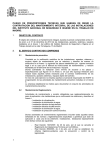
Honeywell
Q7055A
BUILDING NETWORK ADAPTER BNA-1C/2CS/2DN
BUILDING NETWORK ADAPTER BNA-1C/2CS/2DN
Quick Setup
In order to setup the BNA device properly,
the following connections are prerequisite:
•
INSTALLATION INSTRUCTION & USER MANUAL
•
•
•
Null-Modem cable connected to a PC
running a VT100 terminal emulation
program or a VT100 compatible terminal
(refer to Table 6-1: Terminal settings)
LAN connection via UTP (RJ45 connector).
Power connection.
An active FTP-Server machine on the LAN
The following BNA Bootloader commands
are mandatory for setting up the BNA (for a
detailed command description, refer to
chapter 6.5 Command Description on Page
31):
np
Basic network parameters
dc
Download configuration
load
Load executable from FTP server
Before the application firmware is started it
is recommended to add some users (user
roles) using command um (refer to chapter
6.5.8 um - User management on Page 37).
After that, the BNA device can be installed
at its final operating location.
EN1B-0198GE51 R1004B
BUILDING NETWORK ADAPTER BNA-1C/2CS/2DN
Technical Data
Supply Voltage
Power Consumption
Temperature Limits
Ambient storage limits:
Figure 1-1: Parts and Controls on the Front Side
System Data
Processor
Data Transfers
LAN-Interfaces
Field Bus
Figure 1-2: Parts and Controls on the Rear Side
Device Interface
Memory
MTBF
Weight
Dimensions (H x W x D)
Safety
Protection standard
Protection class
Flame retardant
Agency Listings
Electromagnetic compatibility (EMC)
Electromagnetic emission (EME)
Energy management
Fire protection and smoke control
18-24 VAC (50...60 Hz);
18-24 VDC (external power
supply required)
5VA (connected via 10BaseT,
twisted pair); 12VA
(connected via 10Base5)
0...+50 °C (+32...+122 °F);
5...95% rh, non condensing
-35...+70 °C (-31...+160 °F);
5...95% rh, non condensing
25 MHz, MC68EN360, 32 Bit
Microprocessor (4.5MIPS)
10Mbit/sec, 802.3 Ethernet
10BaseT (RJ45)
(BNA-2DN) RS485 AC
coupled Manchester encoded
channels (L1-Bus compatible)
(BNA-2CS/1C) RS485 DC
coupled
Serial RS232
4 MB SRAM, 2 MB Flash
>100.000 h
800 g (1.76 lb)
(76 x 158 x 200) mm
(2.99 x 6.2 x 7.87) in.
IP20 as per EN60529
II as per EN60730-1
V0 as per UL94
EN50081-1 and EN50082-2
FCC Class A
UL916
UL864
EN1B-0198GE51 R1004B
BUILDING NETWORK ADAPTER BNA-1C/2CS/2DN
Table of Contents
1
About BNA........................................................... 5
2
Location of Parts and Controls.......................... 8
2.1 Front Side.................................................... 8
2.2 Rear Side................................................... 11
3
Before Installation ............................................ 13
4
BNA Operating Positions ................................ 15
4.1 Single Device............................................ 15
4.2 Stacked Devices ....................................... 16
4.3 Wall Mounting......................................... 16
5
Connections ....................................................... 19
5.1 Power Connection ................................... 19
5.2 Field Bus Connection (Ch1 / Ch2) ........ 20
5.3 Bus Termination Switch.......................... 20
5.4 L1 Bus Termination ................................. 22
6
BNA Bootloader ................................................ 23
6.1 Startup Behavior ...................................... 23
6.2 Operating Modes..................................... 25
6.3 Switching the Operating Mode.............. 25
6.4 Device Setup............................................. 28
6.5 Command Description............................ 31
6.5.1
6.5.2
6.5.3
6.5.4
6.5.5
6.5.6
6.5.7
6.5.8
6.5.9
6.5.10
EN1B-0198GE51 R1004B
Help or ? .......................................................... 32
np - Basic network parameters.................... 32
dc - Download configuration ...................... 33
load - Load executable .................................. 36
ping - ping ..................................................... 36
ver - Show installed software ...................... 37
run - Execute installed software .................. 37
um - User management................................. 37
whoami - Who am I ....................................... 40
login - Login as different user....................... 40
BUILDING NETWORK ADAPTER BNA-1C/2CS/2DN
7
Cables and Connectors..................................... 42
7.1 DB9F Null Modem Cable ....................... 42
7.2 Ethernet Connectors................................ 44
7.2.1
7.2.1.1
7.2.1.2
RJ45 Connector............................................... 45
Connecting a BNA to a Hub ......................... 45
Connecting a BNA to a Workstation............ 46
Tips & Tricks ............................................................ 48
FAQs........................................................................... 49
Glossary..................................................................... 50
4
EN1B-0198GE51 R1004B
BUILDING NETWORK ADAPTER BNA-1C/2CS/2DN
1 About BNA
Honeywell
XBS
TCP/IP LAN
BNA-2CS
BNA-1C
XCL5010
XCL5010
BNA-2DN
XCL5010
C
B
u
s
XCL5010
S-Bus
F&S Bus
L1 Bus
The Building Network Adapter (BNA) delivers exceptional price/performance to meet the requirements of both building owners and service providers. With its combination of scalable performance, density, and low per-port pricing, the
Building Network Adapter allows network-layer
capabilities to be extended to a much wider range
of network configurations and environments.
Customers can now gain the advantages of highperformance network and services, including traffic
management to more locations throughout the
network.
The Building Network Adapter uses the LAN-connection to provide seamless communication to the
EN1B-0198GE51 R1004B
5
BUILDING NETWORK ADAPTER BNA-1C/2CS/2DN
requesting device. Status information like LAN
communication activity, field bus traffic communication,
and system heartbeat of the Building Network
Adapter is indicated by LEDs on the front.
Technically, the Building Network Adapter provides an interface from various Honeywell controller busses that use RS232/RS485 signals to a
local area network using 802.3 Ethernet protocol.
This allows data to be used by high-level building
management systems such as Enterprise Buildings
Integrator (EBI), Excel Building Supervisor (XBS),
and Excel Facility Integrator (XFI).
This Installation Instruction and User Manual covers
all of the BNA device types listed below.
BNA-1C
provides a single RS485 DC coupled CBus-compatible communication channel for XL5000 family devices with up
to 76.8 kbps.
BNA-2CS provides two RS485 DC coupled C- / S/ FS-90-Bus compatible communication channels for different applications,
like Excel IRC and Excel Classic as well
as XL5000 family devices with up to
76.8 kbps.
BNA-2DN provides two RS485 AC coupled Manchester encoded L1-Bus (DeltaNet Peer
bus)
compatible
communication
channels.
6
EN1B-0198GE51 R1004B
BUILDING NETWORK ADAPTER BNA-1C/2CS/2DN
Additionally, each BNA type is equipped with a
RJ45 10Base T connector plus an RS232 interface.
EN1B-0198GE51 R1004B
7
BUILDING NETWORK ADAPTER BNA-1C/2CS/2DN
2 Location of Parts and Controls
The numbering for the parts and controls in this
section refers to the pictures on the rear side of the
title page. In order to have a reference between the
numbering here and the device pictures, it is
possible to fold this page out.
2.1
Front Side
Differences between the various BNA types are
explicitly noted in the corresponding element
description.
8
1
Reset
Hardware reset button. Located directly behind
the small hole in the front panel. To reach this
button, a pointed object like a sharp pen or an
unfolded paper clip is necessary. Pressing this
button resets the BNA device immediately. This
operation is similar to "power on" with the
BNA device.
2
Mode
Mode switch button. This button is needed to
change the bootloader modes. For a detailed
description about BNA operation modes, please
refer to chapter 6.2 Operating Modes on Page 25.
3
LAN
Local Area Network (LAN) activity display.
EN1B-0198GE51 R1004B
BUILDING NETWORK ADAPTER BNA-1C/2CS/2DN
Shows the actual LAN traffic using 4 LEDs.
Col
Collision indicator (Red). If this LED is
on, then two or more devices on the
network are transmitting at the same
time. This is not a fault, but a normal
occurrence on an Ethernet network.
However, when the Collision LED
remains on for all transmission attempts,
it may indicate an abnormal condition
such as an open end-of-line termination.
Rx
Receive indicator (Green) on means that
data is being received by the BNA over
the Ethernet.
Tx
Transmit indicator (Green). If this LED
is lit up, the BNA device is sending data
to the Ethernet. When data is being
transmitted, the Rx indicator LED is lit
up simultaneously.
Ln
Link indicator (Green) will always be lit
when the BNA is connected via the RJ45
connector to the Ethernet. If this LED is
dark, it will not be possible to send or
receive any data.
k
4
Ch1
Bus Channel 1 activity display. This display
contains two green LEDs, one showing BNA
EN1B-0198GE51 R1004B
9
BUILDING NETWORK ADAPTER BNA-1C/2CS/2DN
reception activity (Rx) and the other showing
BNA transmission activity (Tx).
5
Ch2
Bus Channel 2 activity display. This display
contains two green LEDs, one showing BNA
reception activity (Rx) and the other showing
BNA
transmission
activity
(Tx)
N O T E : Ch2 indication is available on twochannel devices only. It is not available on a
BNA 1C device.
10
6
Heartbeat
System heartbeat display. During BNA system
runtime, this LED flashes continuously. This
LED is a two-color LED. A red flashing LED
means that the BNA bootloader is currently
active. A green flashing LED means that an
application firmware is running.
7
Power
Power indicator. This LED lights up when
power is connected to the BNA device.
EN1B-0198GE51 R1004B
BUILDING NETWORK ADAPTER BNA-1C/2CS/2DN
2.2
Rear Side
Differences between the various BNA types are
explicitly noted in the corresponding element
description.
8
Ch2
3-pin connector for field bus channel 2
connection electrically isolated meets the
EMC-and FCC-requirements.
Field Bus wiring is described in chapter 5.2
Field Bus Connection (Ch1 / Ch2) on Page 20.
N O T E : The Ch2 field bus connector is
available on two-channel devices only. It is
not available on a BNA 1C device.
9
Ch1/Ch2 Bus Termination Switches
These switches are used to select between
different field bus terminations. For a detailed
description of the different Bus Termination
Switch positions, please refer to chapter
5.3 Bus Termination Switch on Page 20.
NOTE:
The
Bus Termination Switch
option is available on BNA 1C and BNA 2CS
devices only.
The Bus Termination Switch near the Ch2
field bus connector is available on twochannel devices only. It is not available on a
BNA 1C device.
EN1B-0198GE51 R1004B
11
BUILDING NETWORK ADAPTER BNA-1C/2CS/2DN
10
Ch1
3-pin connector for field bus channel 1
connection electrically isolated meets the
EMC-and FCC-requirements. Field Bus wiring
is described in chapter 5.2 Field Bus Connection
(Ch1 / Ch2) on Page 20.
11
AC/DC IN 18-24V
Power connector for 18-24V AC (50...60Hz) or
18-24V DC power supplies.
Power consumption is 5VA (connected via
10BaseT, twisted pair) or 12VA (connected via
10Base5). An external power supply is
required. See also chapter 5.1 Power Connection
on Page 19.
12
RS232
9-pin SUB-D male RS232 connector,
electrically isolated, PC pin compatible,
protected against spikes.
This interface is used for initial device set-up
and requires a standard Null-Modem cable
when interfacing to a PC.
13
12
10BaseT
10BaseT RJ-45 Ethernet LAN-connector, meets
the requirements of ANSI/TIA/EIA 586
Category 5, for unshielded twisted pair
connections.
EN1B-0198GE51 R1004B
BUILDING NETWORK ADAPTER BNA-1C/2CS/2DN
3 Before Installation
Please pay attention to the steps listed below prior
to installing the Building Network Adapter device.
1
Verify that the product has been received
without damage.
2
Verify that the correct BNA type has been
delivered.
3
Check package contents. The following items
are included in each product package:
Pieces
Item
1
Building Network Adapter device
1
Building
Installation
Manual
1
Small bag with installation material
Network
Instruction
Adapter
& User
The small installation material bag contains the
following parts:
Pieces
1
EN1B-0198GE51 R1004B
Item
2-pole Phoenix power connector
13
BUILDING NETWORK ADAPTER BNA-1C/2CS/2DN
Pieces
Item
2
3-pole Phoenix controller
channel connectors
4
Optional wall mounting clips
4
Small inserts
4
Screws
bus
4
Please read chapter 5 Connections on page 19
carefully prior to connecting any power and
data interface cables to the BNA.
5
Please refer to the installation instruction
manuals of each component that shall be
connected to the BNA, like 95-7545 XLS1000
Installation
Instructions,
95-7421
FS90
Installation Instructions, and 95-7551 LAN
Installation Instructions, etc.
WARNING:
Do not remove the cover of a BNA device.
There are no user-serviceable parts inside.
Any unauthorized modification of this equipment
may result in the revocation of the owner's
authority to continue its operation.
14
EN1B-0198GE51 R1004B
BUILDING NETWORK ADAPTER BNA-1C/2CS/2DN
4 BNA Operating Positions
4.1
Single Device
Figure 4-1: Single device operating position
Figure 4-1 shows the normal BNA device operating
position e.g. on a desk.
EN1B-0198GE51 R1004B
15
BUILDING NETWORK ADAPTER BNA-1C/2CS/2DN
4.2
Stacked Devices
Figure 4-2: Stacked Devices
BNA Devices may also be stacked. Because of
stability issues, it is recommended not to stack
more than 3 devices.
4.3
Wall Mounting
It is also possible to mount the BNA device to a
wall. The following sequence describes how the
16
EN1B-0198GE51 R1004B
BUILDING NETWORK ADAPTER BNA-1C/2CS/2DN
device has to be prepared prior to mounting it to a
wall.
Put the BNA-adapter with the
top side down on the desk
(Figure 4-3).
Figure 4-3
Remove the four feet (Figure
4-3) from the bottom of the
BNA by pushing them
horizontally away from the
housing with a flat screwdriver (Figure 4-4).
Figure 4-4
Push
the
four
inserts
(included) fully and horizontally into the housing
(Figure 4-5).
Figure 4-5
EN1B-0198GE51 R1004B
17
BUILDING NETWORK ADAPTER BNA-1C/2CS/2DN
Adjust the four retaining clips
(included) on top of the
inserts. Fasten the retaining
clips with the included four
screws (Figure 4-6).
Figure 4-6
Figure 4-7
18
Use the housing with the clips
to mark the positions of the
four mounting holes on the
wall surface. Drill ∅ 4mm
(~0.16 inch) holes for the
mounting
screws
(not
included) and fix the BNA
device.
EN1B-0198GE51 R1004B
BUILDING NETWORK ADAPTER BNA-1C/2CS/2DN
5 Connections
This chapter describes how to connect power and
the field bus to the BNA device.
Together with the BNA device, a supply pack with
installation material is delivered containing the
required connectors for power and field bus.
5.1
Power Connection
For the BNA device, an external power supply with
the following specification is required:
18-24V AC (50...60Hz) or 18-24V DC.
Power consumption of the BNA device is 5VA
(connected via 10BaseT, twisted pair) or 12VA
(connected via 10Base5).
For the power connection, the 2-pole Phoenix
connector is required (included). If an off-the-shelf
power supply is used, cut off the original connector
at the end of the cable. Then strip the two cable
ends and insert each cable end into the openings of
the 2-pole Phoenix connector. Fasten them with a
screwdriver.
The polarity (+/-) of the 2-pole Phoenix power
connector for DC power supplies is don’t care.
EN1B-0198GE51 R1004B
19
BUILDING NETWORK ADAPTER BNA-1C/2CS/2DN
5.2
Field Bus Connection (Ch1 / Ch2)
Regardless of the type of BNA device, the wiring of
the field bus connector is always identical.
For connecting the field bus, the 3-pole Phoenix
connectors (included) are required.
A
C+
1
B
C2
GND
Figure 5-1
Figure 5-1 shows the pin layout of the field bus
connectors Ch1 and Ch2. Pins 1 and 2 shall be used
to connect the field bus.
5.3
Bus Termination Switch
This section applies to BNA 2CS and BNA 1C
devices only.
The Bus Termination Switch is used to select
between different field bus terminations on DC
coupled RS485 busses.
20
EN1B-0198GE51 R1004B
BUILDING NETWORK ADAPTER BNA-1C/2CS/2DN
For each channel the required termination setting
can be adjusted individually.
At the rear side of the device, a pictogram (Figure
5-2) symbolizes the different possible bus
terminations.
Figure 5-2
normal
XD505 compatible bus termination for
C- /S- /FS90-Bus connections
It is required to use this switch position
for S-Bus and FS90-Bus in any case. For
C-Bus connections, this position must
be used when at least one XL IRC or
XL MC is connected to the C-Bus.
XD508 compatible; bus termination
disabled
XD508 compatible switch position for
C-Busses equipped only with XL500
family controllers with bus termination
disabled. This switch position must be
used if the BNA device is installed in
the middle of such a C-Bus.
EN1B-0198GE51 R1004B
21
BUILDING NETWORK ADAPTER BNA-1C/2CS/2DN
XD508 compatible; bus termination
enabled
XD508 compatible switch position for
C-Busses equipped only with XL500
family controllers with bus termination
enabled. This switch position must be
used if the BNA device is installed at
the end of such a C-Bus.
5.4
L1 Bus Termination
This section applies to BNA 2DN devices only.
The required L1 bus EOLRs (End of Line Resistors)
can be connected externally onto each CH1 / CH2
connector.
When the L1 bus uses 18 gauge, twisted pair, nonshielded wire, the ends of the line should be
terminated with a 62 Ω ±10% 0,5 W carbon resistor
between each wire and ground.
When the L1 bus uses 24 gauge, dedicated solid
copper pair, standard balanced telephone cable, the
ends of the line should be terminated with a
100 Ω ±5% 0,5 W carbon resistor between each wire
and ground.
For further information regarding L1 bus
termination, please refer to Honeywell DeltaNet
R7044 EXCEL PLUS CONTROLLER Application
Guide 74-2548, Rev.2/93.
22
EN1B-0198GE51 R1004B
BUILDING NETWORK ADAPTER BNA-1C/2CS/2DN
6 BNA Bootloader
This chapter describes the functions of the BNA
Bootloader software. Each BNA device is equipped
with a Bootloader, which functions in the same way
for all BNA device types.
N O T E : BNA Devices are not equipped with any
application firmware. This must be loaded into
the device prior to using it.
6.1
Startup Behavior
After resetting or power-on the BNA device, all
LEDs on the front will be switched on. Immediately
after that, the BNA Bootloader starts working.
When the BNA Bootloader is active, the heartbeat
LED on the BNA front panel flashes RED.
In contrast, any running application firmware
indicates its execution with a GREEN flashing
heartbeat LED.
The Flowchart depicted in Figure 6-1 explains the
BNA execution sequence. It is necessary that the
user understand this in order to be able to react to
or influence the behavior of the BNA device.
Furthermore, it helps in understanding the current
device state to look at the LEDs on the front panel
of the BNA.
EN1B-0198GE51 R1004B
23
BUILDING NETWORK ADAPTER BNA-1C/2CS/2DN
Start
In case of any error
heardbeat blinking stops and
LED will be permanently on
for 5 Seconds. Then BNA
restarts.
Initialize Hardware
Heartbeat LED Blinks
RED
New
Download?
Download new
Firmware to
Flash Memory
No
Mode
Button
pressed?
No
Yes
Yes
No
Firmware in
Flash?
No
Very First
Run?
No
Stay in
Bootloader?
Yes
Start
Firmware
Yes
Ask for root
password
Yes
Run Booloader
Command Shell
Figure 6-1: BNA Bootloader Execution
24
EN1B-0198GE51 R1004B
BUILDING NETWORK ADAPTER BNA-1C/2CS/2DN
6.2
Operating Modes
The BNA Bootloader provides two different
operating modes:
•
•
Normal Mode
Stay in Bootloader Mode
(default)
Normal Mode is the default, which directly starts an
application firmware found in Flash memory. If no
firmware could be found, then the bootloader
command shell is started by the BNA (Figure 6-1).
This execution flow can be influenced only by
pressing the Mode Button and changing the mode
to Stay in Bootloader Mode.
Stay in Bootloader Mode interrupts the default bootloader startup sequence and tells the bootloader not
to start an possible existing application firmware in
the Flash memory.
6.3
Switching the Operating Mode
In order to switch the Bootloader operating mode, a
pointed object, like an unfolded paper clip or a
sharp pen, is required.
For changing the operating modes, there is a time
window of about 3 seconds after reset. The
following steps must be performed to successfully
change the bootloader mode (Refer also to Figure
6-2: Switching BNA Operating Mode):
1.
Press the Reset Button
EN1B-0198GE51 R1004B
25
BUILDING NETWORK ADAPTER BNA-1C/2CS/2DN
2.
Wait until the heartbeat LED starts flashing
RED, then press the Mode Button.
3.
The heartbeat flashing immediately stops and
the LED is permanently on. The operating
modes are displayed using the LAN status
LEDs Lnk, Tx, Rx. The Normal Mode is
represented via the Lnk LED.
4.
Now push the Mode Button again and the Tx
LED will also be switched on. Two LEDs on
means Stay in Bootloader Mode is selected.
5.
To accept one of the modes, push the Mode
Button again and hold it for about 1 second.
The BNA Bootloader feedback that the mode
has been accepted is indicated with all Mode
LEDs and the heartbeat LED flashing four
times.
If there is no need to change the mode after the
mode button has been pressed, then just stop
pressing the mode button. The BNA device will
continue with its normal work after a few seconds.
26
EN1B-0198GE51 R1004B
BUILDING NETWORK ADAPTER BNA-1C/2CS/2DN
Start
Press Reset
Button
Mode
Button
pressed?
No
Yes
Heartbeat blinking stops.
LEDs LNK, Tx and Rx are
representing current mode.
Bootloader continues with
normal operation after 3
seconds.
Normal Mode
(default)
Mode
Button
pressed?
No
Yes, < 1 sec
Yes, < 1sec
Stay in
Bootloader
Mode
Mode
Button
pressed?
No
Yes, > 1 sec
All LEDs representing the mode
and the heartbeat LED blinks 4
times confirming the selection.
Bootloader continues with
normal operation after 5
seconds.
Figure 6-2: Switching BNA Operating Mode
EN1B-0198GE51 R1004B
27
BUILDING NETWORK ADAPTER BNA-1C/2CS/2DN
6.4
Device Setup
In order to setup the BNA device properly, the
following connections are necessary:
•
•
•
•
DB9F Null-Modem cable connected to a PC
running a VT100 terminal emulation program or a
VT100 compatible terminal (refer to Table 6-1:
Terminal settings)
LAN connection via UTP (RJ45 connector).
Power connection.
An active FTP-Server machine on the LAN
Terminal type:
VT100
Bits per second:
115200
Data bits:
8
Parity:
none
Stop bits:
1
Flow control:
none
Table 6-1: Terminal settings
After having connected all necessary cables to the
BNA, press the Reset button. If the terminal settings
are all Ok, the Copyright notice of the BNA device
will be displayed.
If this is the very first run of the device, then the
Copyright notice is followed by the query for the
28
EN1B-0198GE51 R1004B
BUILDING NETWORK ADAPTER BNA-1C/2CS/2DN
root user password. At the Old password:
prompt, just hit the Enter-Key.
Once a password has been defined the BNA prints
the information User 'root' logged in. for
all future startups.
The root user is the administration user with
unlimited access rights. The root user will be logged
in automatically without any login procedure when
connecting to the BNA device via the serial link
(RS232). Any connection to the BNA via LAN is
password protected!
If the device already contains an application
firmware, then it is necessary to put the device into
the Stay in Bootloader Mode prior to the setup
activity (refer to chapter 6.3 Switching the Operating
Mode on Page 25 how this can be done).
To prepare the BNA device to operate on the LAN
and to load the application firmware into the
device, the following mandatory commands must
be executed in the order they are listed (for a
detailed command description, refer to chapter
6.5 Command Description on Page 31):
np
EN1B-0198GE51 R1004B
Basic network parameters
Definition of IP address, network mask
and default gateway. These definitions
are required to allow the BNA device to
operate on the LAN.
29
BUILDING NETWORK ADAPTER BNA-1C/2CS/2DN
CAUTION:
Using unallowed IP-Addresses
interference on the network.
could
cause
Please contact your network administrator to
retrieve a unique IP-Address. If you want to connect the BNA to a customer network, make sure to
get in touch with the customers IT manager to
retrieve this IP-Address information.
dc
Download configuration
Definition of FTP server, path to
firmware and user account on FTP
server. This is necessary for loading the
application firmware into the BNA
device.
load
Load executable from FTP server
This command finally loads the
application firmware (executable) into
the BNA device. After successful download, the application firmware is moved
into the Flash memory.
This is the minimum command sequence for setting
up a BNA device.
After that the application firmware can be invoked
by entering the command run or by pushing the
Reset button. When the Reset button is pushed, the
BNA Bootloader behaves as depicted in Figure 6-1
on Page 24.
30
EN1B-0198GE51 R1004B
BUILDING NETWORK ADAPTER BNA-1C/2CS/2DN
As mentioned above, the three commands are the
minimum required commands for setting up a
BNA device. We recommend also performing some
user definitions (see command um) for different
user roles. Doing so prevents unfamiliar users from
performing accidental redefinition of important
settings. Furthermore, user definitions can also be
referenced by the application firmware.
6.5
Command Description
The BNA Bootloader provides a command shell
allowing input of several commands. Some of the
commands provide sub-shells which themselves
provide another set of commands to enter.
This chapter describes all BNA Bootloader
commands in detail. The order of the command
descriptions in this chapter follows the order of the
commands displayed by the BNA Bootloader shell
except for the command help. This has been placed
at the front because it is necessary to get the list of
commands displayed.
The following notational conventions apply to this
chapter unless otherwise noted:
cmd
Bootloader command
<key>
A key that has to be pressed, like
<Enter>.
Text
Text written with this font shows
terminal output.
EN1B-0198GE51 R1004B
31
BUILDING NETWORK ADAPTER BNA-1C/2CS/2DN
N O T E : All BNA Bootloader commands are casesensitive!
6.5.1
Help or ?
Entering help or ? at the BNA bootloader>
prompt followed by <Enter> displays all available
BNA Bootloader commands.
In each sub-shell help or ? can also be used to view
the existing commands.
All command lists can vary between different users.
The lists don’t show any commands which a user is
not allowed to execute.
6.5.2
np - Basic network parameters
The basic network parameters command np is used
to define the IP address, the network mask, and the
default gateway of the BNA device. This information is normally provided by the local IS
department.
np is not a direct command; instead, it provides a
sub-shell with the following commands:
32
display
displays current basic network settings.
modify
changes basic network settings. After
entering this command, each basic network parameter will be queried
individually. After having entered all
requested information, it will be asked
EN1B-0198GE51 R1004B
BUILDING NETWORK ADAPTER BNA-1C/2CS/2DN
whether to take over the new settings.
If this is denied, the old settings will be
restored. Otherwise, the new settings
are stored to the Flash memory and the
system needs to be restarted to activate
the new settings.
6.5.3
delete
deletes basic network settings. Please
note that after this operation the BNA
device will not operate on the LAN
anymore. After commanding delete,
new basic network parameters must be
entered via modify.
altmac
definition of an alternative MACaddress. This command is available
only for the sake of completeness. Each
BNA already comes with a unique
Ethernet address (MAC address). So
there will be no need to define a new
MAC address. It is recommended to
not use this command unless advised to
do so by the Honeywell Technical
Assistance Center.
exit
exits the sub-shell and returns to the
main shell.
dc - Download configuration
The download configuration command dc is used
to have a predefined way of retrieving new
application firmware versions when an update of
the same becomes necessary.
EN1B-0198GE51 R1004B
33
BUILDING NETWORK ADAPTER BNA-1C/2CS/2DN
Command dc defines the IP address of the FTPServer, the path to the application firmware, a
username on the FTP-Server and the user’s password. This command must be invoked prior to
using command load.
Prerequisite for downloading an application
firmware is a running FTP-Server machine somewhere in the network that can be reached by the
BNA device. The FTP-Server machine is responsible
for storing the application firmware image to be
loaded into the BNA device. The application firmware image for the BNA is delivered on the
distribution media of the Building Management
System currently in use.
The description of how to set up and invoke an
FTP-Server on each specific operating system is not
within the scope of this document. Please refer to
the documentation set of the operating system used
on the machine that has been selected for the role of
the FTP-Server.
dc is not a direct command; instead, it provides the
following commands in a sub-shell:
34
display
displays current download configuration.
modify
changes download configuration. After
entering this command each download
configuration item will be queried
individually. After having entered all
requested information, it will be asked
whether to take over the new settings.
EN1B-0198GE51 R1004B
BUILDING NETWORK ADAPTER BNA-1C/2CS/2DN
If this is denied the old settings will be
restored. Otherwise, the new settings
are stored to the Flash memory. These
settings are immediately active.
delete
delete download configuration. After
this operation command load can’t be
used anymore. New download configuration definitions must be entered
using the command modify.
test
tests current download configuration.
This command can be used to check
whether the entered download configuration is valid or not.
With the command test, optional
command-line parameters are allowed.
Accepted parameters are FTP-Server IPAddress and/or a filename for checking
existence. Given command-line parameters temporarily supercede the
values in the actual download configuration.
N O T E : With some Windows NT
based FTP-Servers, it has been observed that this command sometimes
fails the first time. If so, we recommend retrying it. If it still fails, one of
the parameters may be wrong.
exit
EN1B-0198GE51 R1004B
exits the sub-shell and returns to the
main shell.
35
BUILDING NETWORK ADAPTER BNA-1C/2CS/2DN
6.5.4
load - Load executable
The command load is a direct command which
immediately starts downloading the application
firmware image into the BNA based on the
download configuration defined by the command dc.
After loading the image into local memory, the
BNA Bootloader starts copying the image into the
local Flash memory where it resides until updated
the next time.
load accepts optional command-line parameters.
Accepted command-line parameters are FTP-Server
IP-Address and/or filename. Command-line parameters supersede the current download configuration for these elements. Command-line parameters in the load command scope can be used to
use an alternative FTP-Server for downloading or
to download another application firmware image
into the BNA device.
If load fails, then it needs to be checked whether the
correct download configuration has been defined.
In this case, the command dc test becomes useful.
6.5.5
ping - ping
Sends an ICMP Ping through TCP/IP to the FTPServer defined in the download configuration or to
the machine addressed by the IP-Address in the
optional command-line parameter.
This command can be used to check whether the
network connection is working properly.
36
EN1B-0198GE51 R1004B
BUILDING NETWORK ADAPTER BNA-1C/2CS/2DN
6.5.6
ver - Show installed software
The command ver outputs a list of all installed
software components on the current BNA device.
6.5.7
run - Execute installed software
The command run starts a previously-installed
application firmware.
If no application firmware could be found, then the
information No executable found is printed
out. In this case, use load to download an
application firmware.
6.5.8
um - User management
The user management command um allows the
definition of users, different access rights per user
and user individual password settings.
User definitions are necessary to provide a secure
device on an open TCP/IP network. Furthermore it
may not be desired that every user will be allowed
to do everything with a BNA device.
These user accounts are required only for set-up,
configuration and diagnostic applications if available. The communication protocols allowing the
communication between BNA and its building
management system are protected at the protocol
level depending on the type of application firmware.
EN1B-0198GE51 R1004B
37
BUILDING NETWORK ADAPTER BNA-1C/2CS/2DN
It is recommended to define several user roles
because also an application firmware may use these
user definitions to behave different in potentially
provided user interfaces depending on the user
who is currently logged in.
A BNA device allows up to 5 user definitions with
different access rights. The root user already
occupies one of these five definitions. Thus, four
additional users or, more accurately, user roles can
be defined.
A user definition consists of three elements. These
are a username or role name, a group membership
and finally a password.
Usernames and password are freely definable. Both
have a maximum length of 8 character. Whereas the
group definitions are predefined, each has specific
characteristics.
Table 6-2 gives an overview of the available user
groups and their properties.
38
EN1B-0198GE51 R1004B
BUILDING NETWORK ADAPTER BNA-1C/2CS/2DN
user
View only rights.
Users who are member of this group
are not allowed to change or delete
any existing definition.
priv
Privileged rights.
Users of the privileged group are
allowed to change several definitions
like network parameters but they are
not allowed to perform delete
operations. Furthermore, privileged
users have no right to perform any
user management.
admin
Administrative users.
Administrative users have full rights.
The root user belongs to the admin
group.
Table 6-2: BNA user groups
The user management command um is an indirect
command and provides the following commands in
its sub-shell:
display
display current user definitions.
add
add new user. Optionally, the
username can be passed directly on the
command-line.
EN1B-0198GE51 R1004B
39
BUILDING NETWORK ADAPTER BNA-1C/2CS/2DN
6.5.9
delete
deletes existing user. Optionally, the
username can be passed directly on the
command-line. Furthermore, an option
–all is available that deletes all user
definitions except the one for the root
user. The root user account can’t be
deleted.
setpass
set other user’s password. This
command is helpful when a user has
forgotten his password. Optionally, the
username can be passed directly on the
command-line.
passwd
set own password. Every user can use
this command to change his own
password.
exit
exits the sub-shell and returns to the
main shell.
whoami - Who am I
whoami prints username and group of the user
currently logged in.
6.5.10 login - Login as different user
The command login allows users to change their
role while they are connected to a BNA device.
This command is not that much useful while connected via the RS232 port because in this case the
root user is logged in per default. When using
40
EN1B-0198GE51 R1004B
BUILDING NETWORK ADAPTER BNA-1C/2CS/2DN
bootloader functionality via a network which can
be provided by the application firmware, this
command becomes more interesting.
EN1B-0198GE51 R1004B
41
BUILDING NETWORK ADAPTER BNA-1C/2CS/2DN
7 Cables and Connectors
7.1
DB9F Null Modem Cable
Figure 7-1: Serial connectors
The female connector is numbered as shown below:
1
2
3
4
5
6
7
8
9
42
DCD
RxD
TxD
DTR
Ground
DSR
RTS
CTS
RI
EN1B-0198GE51 R1004B
BUILDING NETWORK ADAPTER BNA-1C/2CS/2DN
Figure 7-2 shows how to configure a Null Modem
Cable DB9F.
RxD
TxD
DTR
DCD
DSR
GND
RTS
CTS
RI
2
2
3
3
4
6
1
1
6
4
5
5
7
7
8
8
9
9
RxD
TxD
DSR
DCD
DTR
GND
RTS
CTS
RI
Figure 7-2: Signal connections for DB9F Null Modem Cable
EN1B-0198GE51 R1004B
43
BUILDING NETWORK ADAPTER BNA-1C/2CS/2DN
7.2
Ethernet Connectors
8-pin modular
(MJ8)
connector RJ-45
Figure 7-3: BNA Ethernet connection
The BNA provides an RJ45 10BaseT connector to
bring the device online on the LAN. This chapter
describes the pin layout of this connector and
shows how the cables must be configured for connecting via 10BaseT (RJ45).
44
EN1B-0198GE51 R1004B
BUILDING NETWORK ADAPTER BNA-1C/2CS/2DN
7.2.1
RJ45 Connector
A lot of Ethernet local area networks use 10BaseT
twisted pair wiring. 10BaseT networks are
physically laid out in a star topology, where each
piece of equipment on the network is connected to
a central hub. The wiring is connected to devices
using a plug that resembles a phone jack, called
RJ45.
Pin Number
Signal Name
1
Transmit (TX) +
2
Transmit (TX) -
3
Receive (RCV) +
4
Reserved
5
Reserved
6
Receive (RCV) -
7
Reserved
8
Reserved
Table 7-1: RJ45 signals
7.2.1.1 Connecting a BNA to a Hub
For connecting a BNA device to a LAN via an
Ethernet Hub the required cable should be configured as shown in Figure 7-4.
EN1B-0198GE51 R1004B
45
BUILDING NETWORK ADAPTER BNA-1C/2CS/2DN
Tx+
1
1
Tx-
2
2
Rx +
3
3
4
4
5
5
6
6
7
7
8
8
Rx -
Figure 7-4:
Tx+
TxRx +
Rx -
Straight through pinning for BNA to Ethernet Hub
connections
7.2.1.2 Connecting a BNA to a Workstation
When a BNA should be directly connected to a
workstation without having an Ethernet Hub in
between a special cable, called crossover cable, is
required.
Figure 7-5 shows how the different signals need to
be connected in this case.
46
EN1B-0198GE51 R1004B
BUILDING NETWORK ADAPTER BNA-1C/2CS/2DN
Tx+
TxRx +
Rx -
1
1
2
2
3
3
6
6
4
4
5
5
7
7
8
8
Figure 7-5:
EN1B-0198GE51 R1004B
Tx+
TxRx +
Rx -
Crossover pinning for BNA to workstation directconnections
47
BUILDING NETWORK ADAPTER BNA-1C/2CS/2DN
Tips & Tricks
Tip 1
To simplify downloading, we recommend reducing (renaming) the
application firmware image name to
the base name of the image in the FTPServer publication directory, e.g.
rename bna_susi_server_v1.0.0.bin to
bna_susi_server.bin.
This has the advantage that even when
updates or upgrades of the application
firmware are delivered, no change is
necessary in each BNA download configuration.
Tip 2
The BNA Bootloader command shell is
able to execute commands in a subshell directly. For example, it is possible
to invoke the command display in subcommand shell np directly from the
BNA Bootloader prompt. Just call:
BNA bootloader> np display
followed by <Enter>.
Tip 3
48
The BNA Bootloader command shell
allows execution of more than one
command by using a “;” between two
commands, e.g.: np display; dc display
<Enter>. When one of the commands
fails, execution is stopped at this point.
EN1B-0198GE51 R1004B
BUILDING NETWORK ADAPTER BNA-1C/2CS/2DN
FAQs
1.
Which terminal type can be used
connecting to the BNA Bootloader?
for
For connecting to the BNA Bootloader, any
VT100 compatible terminal or VT100
compatible terminal emulation program can be
used. For the proper terminal settings, please
refer to chapter 6.4 Device Setup on Page 28.
2.
After power-on or reset, the BNA device does
not show the BNA bootloader menu on my
terminal. How do I get the correct display?
One reason could be that the terminal settings
are not correct. Please verify the actual terminal
settings. For the proper terminal settings please
refer to chapter 6.4 Device Setup on Page 28.
A second reason could be that an application
firmware is already running in your BNA. As
described in chapter 6.1 Startup Behavior on
Page 23 BNA will start an application firmware
automatically after power-on or reset. To access
bootloader mode, you must switch the
operating mode to force the BNA to Stay in
Bootloader Mode. Please refer to chapter
6.3 Switching the Operating Mode on Page 25 for
further information.
EN1B-0198GE51 R1004B
49
BUILDING NETWORK ADAPTER BNA-1C/2CS/2DN
Glossary
10BaseT
10 = 10Mbps,
Base = baseband,
T = twisted pair.
Application firmware
An application firmware is a software
that is needed to operate the BNA
device in a way the Building Management System requires it. An example
for an application firmware is the BNA
SUSI Server software.
50
BNA
Building Network Adapter
EOLR
End of Line Resistor
FTP
File Transfer Protocol
ICMP
Internet Control Message Protocol
IP
Internet Protocol
IRC
Individual Room Control
LAN
Local Area Network
Mbps
mega bit per second
MC
Multi Controller
SUSI
Subsystem Services Interface
TCP
Transmission Control Protocol
EN1B-0198GE51 R1004B
BUILDING NETWORK ADAPTER BNA-1C/2CS/2DN
WAN
Wide Area Network
XD505
C-Bus piggyback type of XL500
controllers.
Compatible with EXCEL IRC devices
on the same bus.
XD508
C-Bus piggyback type of XL500 controllers. This piggyback type allows CBus communication transfer rates up to
76.8 kbps. This piggyback type allows
C-Bus wiring with XL500 controllers
only.
XLCL
EXCEL Classic
EN1B-0198GE51 R1004B
51
BUILDING NETWORK ADAPTER BNA-1C/2CS/2DN
Honeywell
Automation and Control Solutions
Honeywell GmbH
Böblinger Straße 17
D-71101 Schönaich
Phone: (49) 7031 63701
Fax: (49) 7031 637493
http://europe.hbc.honeywell.com
Subject to change without notice. Printed in Germany.
Manufacturing location certified to
DIN
EN ISO 9001
EN1B-0198GE51 R1004


![MobiShow取扱説明書(T04900100003A)[PDF 1.5MB]](http://vs1.manualzilla.com/store/data/006664287_2-73e9aae4ed57e6d712dc2acfe986e5ae-150x150.png)